Bibby Sterilin Distinction D4000 User manual

Distinction
Assembly and
operating instructions
Instructions de montage et
de fonctionnement
D4000 & D4000/EURO Water Still
Distinction

2
Before use
If the equipment is not used in the manner described in this
manual the protection provided by the equipment may be
impaired.
N.B. The Distinction Water Still is classified as “Permanently
Connected Equipment” and should be connected to the
electricity supply by a qualified electrician in the manner
described in the electrical installation section of this manual.
The Distinction Water Still is designed to operate under the
following conditions:
❖ For indoor use only
❖ Ambient temperature range +5°C to +40°C
❖ Altitude up to 2000m
❖ Relative humidity not exceeding 80%
❖ Mains supply voltage fluctuations not greater than
±10% of nominal
❖ Overvoltage category II IEC60364-4-443
❖ Pollution degree 2 IEC664
Limitations of use
This product meets the applicable E.C. harmonised standards for
radio frequency interference and may be expected not to interfere
with, or be affected by other equipment with similar qualifications.
We cannot be sure that other equipment used in its vicinity will meet
these standards and we cannot guarantee that interference will not
occur in practice. Where there is a possibility that injury, damage or
loss might occur if equipment malfunctions due to radio frequency
interference, or for general advice before use, please contact the
Technical Service Department of Bibby Scientific Ltd.
Distinction Water Still
D4000 & D4000/Euro
The Distinction Water Still complies with the
following European Directives:
89/336/EEC - E.M.C. DIRECTIVE
Amended by 92/31/EEC and 93/68/EEC
73/23/EEC - L.V.D. Amended by 93/68/EEC
Figure 1 General assembly
Thermostat reset buttons
Boiler
thermostat
tube
On/Off switch
Clip
Reservoir
level
control Heater Gaskets
and flange
Distillate
outlet tube
Boiler Stand
Stopcock
To drain
Constant
level control
Wall mounting
screw holes
Cooling water
inlet
Condenser
thermostat tube
Condenser
outlet
Straps
Condenser
Condenser
thermostat
Boiler
thermostat
Distinction

3
2. Remove the end cover from the electrical compartment by
undoing the retaining screws in the left hand panel.
3. Take the metal stand and place in the desired location. Note
that 2 screw holes are provided for wall mounting. If wall
mounted the unit should be secured using 38mm (1.5”), No.
10 screws.
4. Take the boiler, the heater and the gasket kit and assemble as
shown in figure 2.
i) Place the bolts through the metal flange in the manner
shown and then place the metal flange over the tapered
glass tube of the boiler.
ii) Take the plastic insert and bend it round the glass tube
and into the metal flange. Pull the flange and insert
towards the open end of the glass tube until the insert
presses on the glass.
iii) Place the aluminium plate, followed by the silicone ring
over the heating element and locate approximately 40-
45mm from the end with the electric cable.
iv) Insert the heating element through the tapered glass tube
and into the boiler – ensure that there is clearance at the
inside end and no danger of the end of the element
pressing against the end of the boiler.
v) Now secure the element using the 3 bolts provided. Do
not overtighten.
Location
The Distinction Water Still can be wall or bench mounted. Select a
convenient location which has access to the following services:-
Electricity Supply
Before connection please ensure that the line supply is suitable. The
Distinction Water Still is available in two models, model no. D4000
for supplies rated at 3kW, 220-240V 50/60 Hz single phase and
model no. D4000/EURO for supplies rated at 3kW, 200-230V,
50/60Hz, single phase.
Water Supply
A cold water supply capable of providing a minimum flow rate of
60 l/hr.
Drain
A waste water drain located below the level of the Still so that the
drain pipe can fall away straight without kinks or bends, to allow an
unimpeded flow.
Reservoir
A distillate collection reservoir should be located beneath the Still.
Assembly
1. Unpack the Still and identify the following components:-
Qty. Component Catalogue No.
1 Support Stand D4000/S
1 Boiler D4000/B
1 Condenser D4000/M2
1 Heating element D240H for D4000
D220H for D4000/EURO
1 Hose kit W4000/HK
1 Gasket kit D4000/GK
1 Boiler thermostat tube WTT48
1 Condenser thermostat tube A515414
2 Plastic connecting caps QC18/11
2 Silicone rubber rings QR18/7 and QR18/10
1 P.T.F.E washer QW18/7
1 Reservoir level control WLS
Figure 2 Heater and thermostat tube assembly
Heater
Aluminium
plate
Silicone
ring Plastic
insert
Metal
flange
Bolts
Boiler
Screwcap
Tapered glass tube
Boiler
thermostat
tube
40-45mm

4
8. From the hose kit take the length of 9mm bore hose fitted with
the plastic screwthread connectors at either end. Referring to
figure 1, screw one end of the hose to the upper outlet of the
condenser and the other end to the glass thread on the
constant level control.
09. From the hose kit take the 1000mm length of 16mm bore hose
and carefully push on to the outlet of the constant level
control. For ease of connection, first warm the end of the hose
with hot water.
Secure with the tie strap provided.
10. Lead the free end of the hose to drain, ensuring it falls away
from the Still with no kinks or bends to impede the water flow.
11. Ensure that the stopcock on the constant level control is closed.
12. Assemble the condenser thermostat tube A515414 connecting
cap QC18/11, silicone rubber ring QR18/7 as shown in figure 4.
If the cap is left loose the assembly may now be carefully slid
over the air vent on the distillate outlet
- see figure 4.
Tighten up the cap once the tube is in place.
Identify the “condenser” thermostat and place the free end of
its probe into the thermostat tube. Carefully bend the capillary
to ensure that it does not obstruct access to the thermostat
reset buttons. - see figure 1.
5. Take the two metal straps and attach the springs to the
rear of the “cradles” on the stand. Place the assembled boiler
and element onto the “cradle” of the stand. Slide the assembly
along until the protruding end of the element is located inside
the electrical compartment and at the same time ensure that
the boiler thermostat probe is located in the thermostat tube.
Attach the free ends of the straps to the front of the cradle to
secure the boiler in place.
N.B. A “pip” on the bottom of the boiler locates in a hole in
the right-hand cradle.
6. Connect the heater cable as shown in figure 3a.
- Ensure screw terminations are tight.
- Push wires fully into block.
7. Fit the condenser WC48/M2 to the vapour tube of the boiler,
ensuring that the distillate outlet faces forward.
13. Connect the lower inlet of the condenser to the cold water
feed. A plastic screwthread connector is provided for easy
attachment.
Select good quality tubing and secure all connections with hose
clips.
Figure 3a
Heater electrical connections
Brown
Brown
Blue
Blue
Heater
cable
Heater
3kW 220/240V
Front
panel
Figure 3b
Mains electrical connections
Yellow/green
Mains
cable
Brown
Blue NL
Figure 4
Assembly of condenser thermostat tube
Condenser
thermostat
Condenser
thermostat
tube
Screwcap
Air vent
Distillate
outlet

5
14. Connect the distillate outlet of the condenser to a suitable
collection reservoir, using a suitable length of 9mm tubing.
A glass reservoir system is available from Bibby Scientific Ltd.
(Catalogue No. WR20). Please contact the sales office for
details.
15. Replace the end panel on to the unit.
16. Take the reservoir control WLS and push the free end of the
rubber tubing onto the nozzle on the left hand end of the unit
- see figure 1.
Use the clip provided to mount the glass pressure bell in the
neck of the distillate reservoir.
Adjust the height of the pressure bell so that the open end is
approx. 140mm below the maximum distillate level.
Electrical installation
THIS EQUIPMENT MUST BE EARTHED!
The electrical installation should be carried out by a qualified
electrician. The following method is recommended.
The equipment is supplied with 1.5m of PVC/PVC flexible, triple
core, circular cable with the following specification, 1.5mm2to
BS 6500 or equivalent and <HAR> or BASEC approved.
The cable gland is designed to accept cable whose diameter is
>7.0mm and <10.5mm. It is recommended that, at the connection
to the mains electrical supply, there is fitted a double pole isolation
switch with a continuous current carrying capacity of 15 amps at
250V, and that overcurrent protection is provided by either a double
pole approved fuse rated at 15A, 250V, or a double pole approved
circuit breaker of similar rating.
These devices should be sited near to the equipment and be clearly
marked “Disconnect device for ‘Distinction’ Water Still”.
NOTE: Do not connect to electricity supply with
a 13 amp plug.
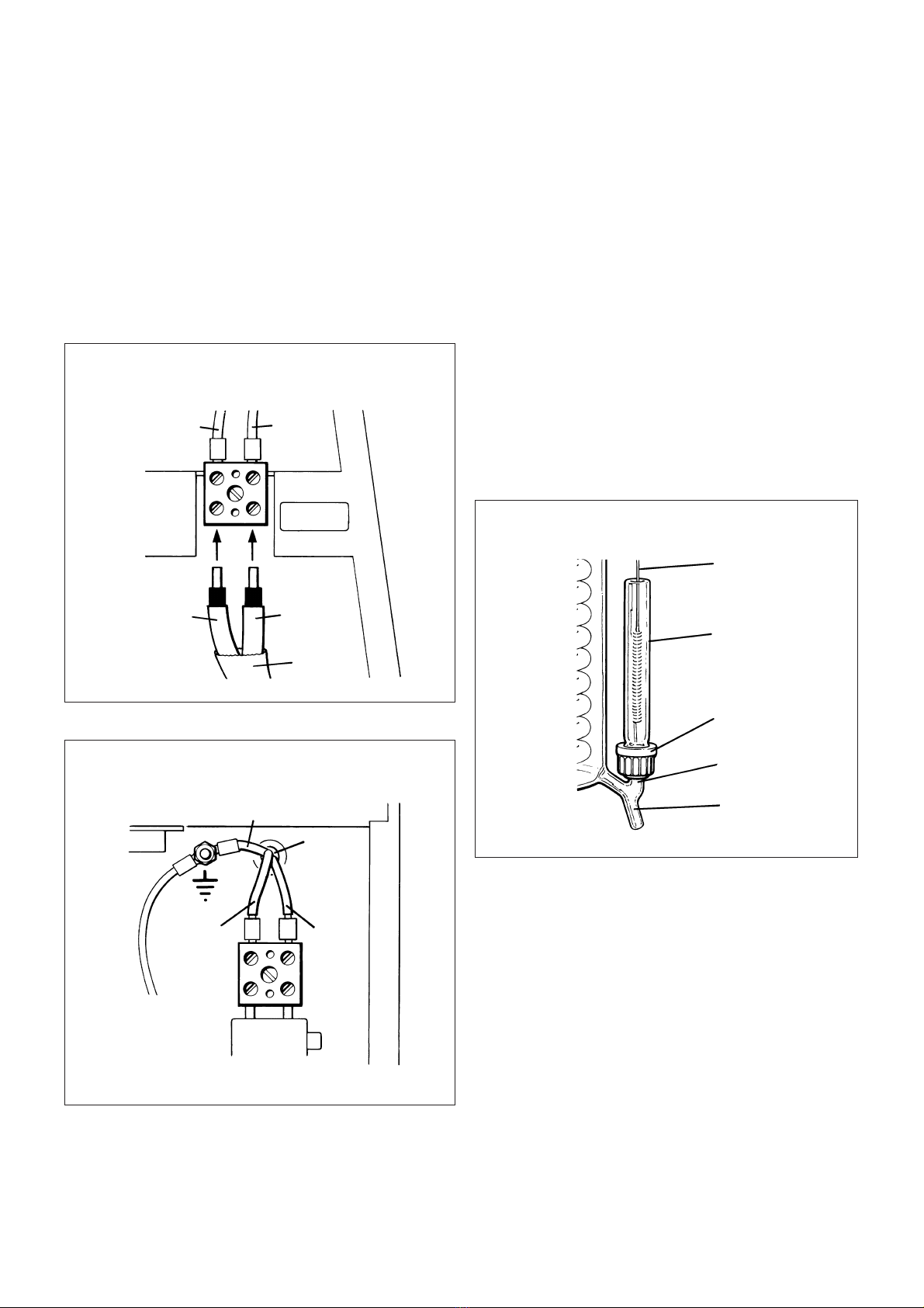
Cable connections are shown in figures 3a and 3b. Connect to the
line supply noting that the wires in the instrument lead are coloured
in accordance with the following code:
Blue - Neutral
Brown - Live
Green & Yellow - Earth
Mains Cable Replacement
If the mains cable requires replacement, only cable with the
specification given above should be used.
For live and neutral leads use bootlace crimps, size 1.5mm, with a
performance conforming to BS 4G178 part 1, 1984 and part 2,
1986.
For the earth lead use 1.5mm, M4 eyelet crimps with a performance
conforming to BS 4G178 part 1, 1984 and part 2, 1986. A suitable
crimp tool should be used.
Operation
1. Turn on the cold water supply and adjust the flow to approx.
60 l/hr. Observe that the water flows via the condenser and
into the boiler. Wait until the boiler has attained its correct
operating level and make sure that the excess water is flowing
freely to drain.
2. Switch on the heating element. The on/off switch is located on
the front panel - see figure 1.
3. After a few minutes the water will start to boil and distillate
will emerge from the condenser. With new glassware, or after
cleaning, it is advisable to allow this to run to drain for
approximately 30 minutes before beginning collection.
4. To turn off the still, first turn off the heating element but allow
cooling water to continue for a further 10 minutes to allow the
Still to cool.
WARNING!
Do not use this equipment to distil any liquid
other than water.
Safety cut-outs
The Distinction Water Still is protected by the following safety cut-
outs:
1. Reservoir level control
This should be positioned in the collecting reservoir (see
“Assembly”) and turns off the heating element when the
reservoir is full.
2. Condenser thermostat
Mounted in the condenser’s distillate outlet. Should the water
supply be interrupted steam will begin to emerge from the
condenser causing the thermostat to operate and turn off the
electricity supply to the heating element.
3. Boiler thermostat
Mounted in the boiler above the heating element. Should the
boiler water level fall and expose the element the thermostat
will operate and turn off the electricity supply to the element.
After operation of either of the thermostats, normal operation may
be resumed by resetting the thermostat by means of their respective
reset buttons mounted on the right hand end panel of the electrical
compartment.
Remove the black plastic cover and then press the red button - a
slight click will be heard if the thermostat had operated.
Before resetting either thermostat the still should be
allowed to cool completely and the cause of the cut-
out operation identified and rectified.
If the thermostats continue to operate, consult a qualified electrician
or the Technical Service Department of Bibby Scientific Ltd.

6
Care and maintenance
N.B. Before commencing any maintenance, cleaning or fault
finding the equipment should be isolated from the
mains electricity supply. These operations should only
be carried out by suitably qualified personnel.
Only spare parts supplied or approved by Bibby Scientific Ltd or its
agent should be used. Fitting of non-approved parts may affect the
performance or safety of the equipment.
Cleaning
Over a period of operation scale will build up inside the boiler. To
obtain optimum performance this scale should be removed on a
regular basis.
Please note that scale can build up both in the neck and main
body of the boiling chamber.
The time span between cleaning depends greatly on the hardness of
the water and the amount of use. Frequently used stills in hard
water areas may need descaling once a week whereas in a soft
water area several weeks may elapse before descaling is necessary.
N.B. Heavy scaling will reduce distilled water quality and can
shorten the life of the heating element.
It is possible to descale the Distinction Water Still without
dismantling the glassware by following these instructions in
conjunction with Control of Substances Hazardous to Health
regulations (COSHH) 1988:
1. Switch off the electricity supply to the still and allow it to cool
completely.
2. Turn off the cooling water supply.
3. Open the stopcock on the constant level control and allow the
boiler to drain completely. Close stopcock.
4. Turn on the cooling water supply and allow the boiler to fill to
approximately half way to its normal operating level. Turn off
the water supply.
5. Into the open funnel of the constant level control carefully add
about 100ml of concentrated hydrochloric acid.
WARNING!
ALWAYS HANDLE STRONG ACIDS WITH GREAT CARE.
PROTECTIVE CLOTHING, GLOVES AND FACE-MASKS
SHOULD BE WORN DURING THE DESCALING OPERATION.
REMOVE ANY ACID SPILLS IMMEDIATELY.
Turn on the water supply and fill the boiler to the normal
operating level. The water will flush the acid into the boiler. The
water supply should be turned off when the level in the boiler
is slightly below the overflow.
6. Leave the acid in the boiler to dissolve the scale. This may take
some time depending on the severity of the build-up.
7. Open the stopcock and allow the boiler to drain.
Note: If the acid in the boiler has not been completely
neutralised the liquid flowing to drain may be highly
acidic. All necessary safety precautions should be
observed around the drain and any effluent control
procedures followed.
8. Close the stopcock, turn on the water and allow the boiler to
fill with cold water. Turn off the water, re-open the stopcock
and allow the boiler to drain.
Repeat this procedure three times.
9. The Distinction Water Still may now be restarted by referring to
the instructions given under “Operation” in this manual.
Note: The stand and outer surfaces of the glassware should be
cleaned using a damp cloth and a mild detergent solution.
Heater replacement*
1. Isolate the Still from the electricity supply.
2. Clean the heater and boiler if they are heavily scaled by
following the cleaning instructions given in this manual.
3. It will be found easier to replace the heater by working with
the boiler “on the bench”.
Therefore:
❖Drain the boiler via the stopcock.
❖Remove the end panel.
❖Disconnect the heater cable.
❖Disconnect all water hoses.
❖Remove the condenser.
❖Remove the boiler, complete with heater, from the stand.
❖Unscrew the 3 bolts securing the heater and
withdraw the heater from the boiler.
❖Remove the aluminium plate and silicone rubber
ring from the heater.
4. Now fit a new heater as described in assembly instruction
number 4.
N.B. Examine the silicone ring and replace if not in good
condition.
5. Re-assemble the Still by following the assembly instructions.
*Note: Heater is not covered by the 3 year warranty.
It is only guaranteed for up to 1000 hours in use.

7
List of spare parts
The following components are available from most
laboratory suppliers. In case of difficulty please
contact Bibby Scientific Ltd.
Component Catalogue No. Component Catalogue No.
Support stand D4000/S Reservoir level control WLS
Boiler D4000/B Boiler thermostat WT4
Condenser WC48/M2 Condenser thermostat W14TS
Heating element 240V D240H Reservoir level control pressure switch DPS
Heating element 220V D220H On/Off switch D4000/SW
Hose kit W4000/HK Boiler O rings Top WB48/01
Gasket kit D4000/GK Bottom QR38/24
Boiler thermostat tube WTT48 Heater sealing ring QR38/24
Condenser thermostat tube A515414
Plastic connecting caps QC18/11
Silicone rubber rings QR18/7 and QR18/10
Fault finding
In the event of operating difficulties with your Distinction Water Still,
please consult the following notes. If these fail to identify and remedy
the fault you are advised to contact your supplier or the
Technical Service Department of Bibby Scientific Ltd.
Symptom Cause Remedy
Heater not working a) Burnt out heater Replace heater
b) Failed electricity supply Restore supply
c) Thermostat operated Identify and rectify the
cause and reset thermostat
Water level in boiler a) Supply of cooling water is Adjust the supply to
is too low - heater exposed insufficient approximately 60 l/hr
b) Boiler drain stopcock left open Close stopcock
Water level in boiler a) Flow of cooling water is too high Adjust the supply to
is too high - e.g. water surging approximately 60 l/hr
into condenser b) Drain is restricted Ensure drain pipe falls freely
from Still with no kinks
Distillate temperature is Supply of cooling water is Adjust the supply to
too high - e.g. >50°C insufficient approx 60 l/hr
Water in boiler is “pumped” a) Tubing from condenser Ensure tubing falls freely
out of the boiler to drain distillate outlet to the reservoir from Still with no kinks
is constricted
b) Mounting for condenser Remove obstruction
thermostat is blocked
c) Supply of cooling water Adjust the supply to
is insufficient approximately 60 l/hr
Distillate quality is poor* Boiler heavily scaled Clean boiler
Output less than 4 l/hr Mains electricity supply below –
nominal voltage
*Distillate quality when measured by pH or conductivity is greatly
affected by temperature and the presence of absorbed
carbon dioxide.

8
Avant utilisation
Si l’appareil n’est pas utilisé dans les conditions décrites ci-
après, la sécurité d’utilisation pourrait s’en trouver altérée.
N.B. Le distillateur d’eau D4000 est classé dans la catégorie
des appareils branchés en permanence. Il doit étre relié à
l’alimentation életrique par un électricien qualifié selons les
instructions de ce manuel. Il ne doit pas être relié à un prise
de courant classique, pur rester en conformité avec le norm
IEC 1010.
Le distillateur d’eau D4000 est conçu pour fonctionner dans les
conditions suivants:
❖A l’intérieur d’une pièce uniquement
❖Température ambiante comprise entre +5°C et +40°C
❖Altitude inférieur à 2000m
❖Taux d’humidité relative inférieur à 80%
❖Variation de voltage de l’alimentation électrique
inférieur à ±10% de la valeur nominale
❖Catégorie de survoltage II IEC 60364-4-443
❖Degré de pollution II IEC 664
Limites d’utilisation
Cet appareil est conforme aux directives Européennes en vigeur
pour les interférences de fréquences radio. Il ne doit donc pas
interférer avec d’autres appareils répondant aux mêmes directives.
Ne pouvant être sûr que d’autres appareils en fonctionment autour
du distillateur soint conformes à ces normes, nous ne pouvons
garantir qu’acune interférence ne se produira en réalité.
En cas de mauvais fonctionment dû aux interférences de fréquence
radio, prière de contacter le service technique de Bibby Scientific
France ou votre revender.
Distillateur d’eau
D4000/D4000-Euro
Le distillateur d’eau est en conformité avec les
normes Européennes:
89/336/EEC - E.M.C. DIRECTIVE
Amendées par 92/31/EEC & 93/68/EEC
73/23/EEC - L.V.D. Amendée par 93/68/EEC
Figure 1 Vue d’ensemble
Boutons de réarmement des
thermostats
Tube du thermostat
bouilleur
Interrupteur Marche/Arrêt
Patte
Contrôleur de niveau
de recette
Elément
chauffant
Joint
d’étanchéité
Tube de sortie
du distillat
Bouilleur
Support
Robinet
Evacuation
Controleur de
niveau
Orifice pour
fixation murale
Entrée d’eau
de refroidissement
Tube du
thermostat
réfrigérant
Sortie du réfrigérant
Collier
métallique de
fixation
Réfrigérant
Thermostat du
réfrigérant
Thermostat
du bouilleur
Distinction

9
Emplacement
Le distillateur D4000 peut être installé sur une paillasse ou fixé au
mur. Choisir un emplacement à proximité des dispositifs suivants:
Alimentation électrique:
Avant de connecter l’appareil, vérifier que l’alimentation électrique
est correcte. Deux modèles de distillateurs DISTINCTION sont
disponibles. Modèle D4000 pour alimentation électrique 3KW 220-
240 V, 50/60 Hz monophasé et modèle D4000/EURO pour
alimentation électrique 3KW, 210-230 V, 50/60 Hz monophasé.
Alimentation en eau:
Source d’eau froid capable de fournir un débit minimum de 60 l/hr.
Evacuation:
Dispositif d’évacuation ou évier situé en dessous de l’appareil de
façon à ce que le tuyau d’évacuation d’eau ne présente aucun
coude.
Réservoir de recette:
Un réservoir de recette du distillat pourra être installé sous l’appareil.
Montage
1. Déballe le distillateur et identifier les composants suivants:
2. Retirer le capot latéral du compartment électrique enlevant les
vis de fixation.
3. Placer le support métallique à l’emplacement choisi. Deux
orifices de fixation sont prévus sur le support pour un montage
mural. Dans ce cas utiliser des vis de 38mm.
4. Prendre le bouilleur, l’élément chauffant et le jeu de colliers, et
assembler selon la figure 2.
i) Insérer les boulons au travers du collier métallique et le
placer autour du tube évasé du bouilleur.
ii) Enrouler le collier en fibre et l’insérer entre le tube évasé et
le collier métallique. Le pliage du collier en fibre est plus
facile après trempage dans l’eau. Tirer le collier métallique
et le collier en fibre vers l’extrémité du bouilleur de façon à
ce qu’ils exercent une pression sur le tube évasé.
iii) Enfiler la plaque aluminium et l’anneau silicone sur
l’élément chauffant jusqu’à 40-45 mm de l’extrémité
munie du cable électrique.
iv) Insérer l’élément chauffant dans le bouilleur au travers du
tube évasé. Verifier que l’extrémité de l’élément chauffant
n’exerce aucune pression sur la paroi latérale interne du
bouilleur.
v) Visser sans trop serrer les boulons sur la plaque
d’aluminium.
Qte Designation Reference
1Support –
1Bouilleur 754.31
1Réfrigérant 753.61
1Elément chauffant pour
D4000/EURO (ou Elément
chauffant pour D4000) 754.32
1Jeu de tuyaux –
1Jeu de colliers por élément 754.34
chauffant
1Tube de thermostat du bouilleur 753.36
1Tube de thermostat du réfrigérant 756.42
2Capuchons plastiques 701.83
2Anneaux silicones 701.84
1Rondelle PTFE 701.85
1Contrôleur de niveau de recette 753.75
Figure 2 Montage de l’élément chauffant
Elément
chauffant
Plaque
d’aluminium
Anneau
silicone
Collier Collier
métallique
Boulon
Bouilleur
Capuchon
Tube évasé
Tube du
thermostat
bouilleur
40-45mm

10
5. Fixer les 2 colliers métalliques de maintien du bouilleur sur les
encoches arrières des pattes arrondies supportant le bouilleur.
Placer le bouilleur sur les pattes arrondies du support. Insérer la
sonde du thermostat du bouilleur dans le tube en verre. Faire
glisser le bouilleur latéralement de façon à ce que l’extrémité
de l’élément chauffant se trouve à l’intérieur du compartment
électrique.
N.B. Un “pointeau” en verre situé sous le bouilleur pénètre
dans une encoche située sur la patte arrondie droite, quand le
bouilleur est en bonne position.
Fixer les 2 colliers métalliques de maintien du bouilleur sur les
encoches avant des pattes arrondies.
6. Brancher les câbles de l’élément chauffant selon la figure 3a.
8. Dans le jeu tuyaux prendre le tuyau de diamètre 9 mm équipé
de connecteurs plastiques à ses deux extrémités. Selon la
figure 1, visser une extrémité sur la sortie du réfrigérant et
l’autre extrémité sur le contrôleur de niveau.
9. Prendre le tuyau de 1000mm de long et 16mm de diamètre.
Enfiler avec précaution son extrémité en sortie du contrôleur de
niveau. Pour faciliter cette opération, passer préalablement
l’extrémité du tuyau sous l’eau chaude. Fixer avec le collier
plastique fourni.
10. Placer l’extrémité libre du tuyau vers l’évacuation, en s’assurant
qu’il ne présente aucun coude pouvant perturber l’écoulement
de l’eau.
11. Vérifier que le robinet du côntroleur de niveau est fermé.
12. Assembler le tube du thermostat du réfrigérant, le capuchon
plastique et l’anneau silicone selon la figure 4.
Le capuchon n’étant pas complètement vissé, glisser
délicatement le tube sur l’évent de la sortie du distillat. Visser
alors le capuchon. Insérer la sonde du thermostat du réfrigérant
dans le tube de verre. Tordre délicatement le fil du thermostat
de façon à ce qu’il n’obstrue pas l’accès aux boutons de
réarmement des thermostats. Voir figure 1.
7. Enfiler le réfrigérant sur le tube vapeur du bouilleur. L’orifice de
sortie du distillat doit faire face à l’utilisateur.
13. Fixer le tuyau d’alimentation en eau sur l’entrée du réfrigérant.
Un connecteur à vis en plastique est fourni à cet effet.
Choisir un tuyau de bonne qualité et renforcer toutes les
connexions par des colliers.
Figure 3a
Raccordement électrique de l’élément chauffant
Marron
Marron
Bleu
Bleu
Câble de
l’élément
chauffant
Elément chauffant
3kW 220/240V
Panneau
frontal
Figure 3b
Raccordement à l’alimentation électrique
Vert/jaune
Câble
Marron
Bleu NP
Figure 4
Montage du tube du thermostat réfrigérant
Thermostat du
réfrigérant
Tube du
thermostat
Capuchon
Event
Sortie du
distillat

11
14. Relier par un tuyau de diamètre 9 mm la sortie du distillat au
réservoir de recette.
Un réservoir en verre PYREX de 20 litres (Réf. 75354) est
disponible en accessoire. Contacter Bibby Scientific France ou
votre revendeur pour plus d’information.
15. Remonter le panneau latéral.
16. Prendre le contrôleur du niveau de recette et enfiler l’extrémité
du tuyau caoutchouc sur la tétine située sur le panneau latéral.
Voir figure 1.
Utiliser éventuellement la patte pour fixer la sonde au bord du
réservoir de recette.
Régler la hauter de la sonde pour que son extrémité libre se
situe environ 140 mm en dessous du niveau maximum de
distillat.
Installation électrique
CET APPAREIL DOIT ETRE RELIE A LA TERRE!
L’installation électrique doit être effectuée par un électricien qualifié.
Nous vous recommandons de suivre la procédure suivante:
L’appareil est livré avec un câble PVC/PVC flexible de 1,5 m, de
section 3 x 1,5 mm répondant aux normes BS 6500 <HAR> et
BASEC.
Le presse étoupe peut accepter des câbles de diamètres compris
entre 7 mm et 10,5 mm.
Il est recommandé de protéger l’appareil par un fusible de
16A/250V, sur la phase et ne neutre ou un disjoncteur bipolaire
16A/250V. Il est également conseillé de connecter l’appareil sur un
interrupteur bipolaire 16A/250V.
Ces protections doivent être placées près de l’appareil et clairement
signalisées.
Voir figure 3a et 3b pour la connection du câble électrique.
Connecter le câble électrique de la manière suivante:
bleu - neutre
marron - phase
jaune/vert - terre
Remplacement du Câble D’Alimentation Electrique
Si le câble d’alimentation électrique nécessite un remplacement,
n’utiliser qu’un câble ayant les mêmes spécifications que celles
citées ci-dessus, et fixer le câble de la manière suivante:
1) Pour la phase et le neutre, utiliser des cosses à sertir de
diamètre 1,5 mm répondant aux normes BS 4 G 178 point 1,
1984 et point 2, 1986.
2) Pour la terre, utiliser un oeillet à sertir de taille M 4 / 1,5 mm
répondant aux normes BS 4 G 178 point 1, 1984 et point 2,
1986.
Une pince à sertir est nécessaire.
Mise en route
1. Ouvrir le robinet d’alimentation en eau froide et régler le débit
à 1 l/mn environ. L’eau doit circuler à travers le réfrigérant.
Attendre que le niveau d’eau dans le bouilleur soit stable.
Vérifier que l’eau s’écoule normalement vers l’évacuation.
2. Allumer l’élément chauffant via l’interrupteur Marche/Arrêt
située sur le panneau frontal.
3. Après quelques minutes, l’eau commence à bouillir et le distillat
s’écoule du réfrigérant. A la mise en route ou après nettoyage,
nous vous conseillons d’attendre 30 mn avant de récoupérer le
distillat.
4. Pour arrêter l’appareil, couper d’abord l’élément chauffant via
l’interrupteur. Attendre ensuite 10 mn avant de couper
l’alimentation en eau, afin de permettre à l’appareil de refroidir.
ATTENTION!
CET APPAREIL NE DOIT PAS ETRE UTILISE POUR DISTILLER
D’AUTRES LIQUIDES QUE L’EAU.
Securités
Le distillateur d’eau D4000 est protégé par les dispositifs de sécurité
suivants:
1. Contrôleur du niveau de recette
Il doit être placé dans le réservoir de recette (voir “Montage”).
Il coupe l’élément chauffant quand le réservoir est plein.
2. Thermostat du réfrigérant
Il est monté sur le tube de sortie du distillat. En cas de rupture
de l’alimentation en eau, de la vapeur est générée au niveau
du réfrigérant. Le thermostat se met alors en fonctionnement
et coupe l’alimentation électrique de l’élément chauffant.
3. Thermostat du bouilleur
Il est situé dans le bouilleur, au-dessus de l’élément
chauffant. En cas de baisse du niveau d’eau dans le bouilleur,
le thermostat se met en fonctionnement et coupe
l’alimentation électrique de l’élément chauffant.
Après fonctionnement de l’un ou l’autre des thermostats, la remise
en route de l’appareil s’effectue en appuyant sur les boutons de
réarmement situés sur le panneau latéral droit du compartiment
électrique.
Enlever le capuchon plastique noir et appuyer sur le bouton rouge.
Vous pourrez entendre alors un déclic témoignant que le
réarmement est effectué.
AVANT DE REARMER UN THERMOSTAT, LAISSER
REFROIDIR L’APPAREIL ET IDENTIFIER LA CAUSE DE
SA MISE EN FONCTIONNEMENT.
Si le thermostat continue de se mettre en route, consulter un
électricien qualifié ou le service technique de Bibby Scientific France.

12
Entretien et maintenance
NB : Avant toute opération d’entretien ou de maintenance,
isoler l’appareil de l’alimentation électrique. Cette
opération doit être effectuée par un personnel qualifié.
Seules les pièces détachées fournies ou approuvées par Bibby
Scientific France ou ses revendeurs devront être utilisées. L’utilisation
de pièces détachées non approuvées peut diminuer les
performances ou la sécurité de l’appareil.
Nettoyage
Après un certain temps de fonctionnement, du tartre peut se
déposer à l’intérieur du bouilleur. Afin d’assurer le bon
fonctionnement de l’appareil, le tartre devra être éliminé
régulièrement.
L’intervalle de temps entre deux nettoyages dépend de la dureté de
l’eau d’alimentation. Dans les régions où l’eau est très dure, il peut
s’avérer nécessaire de nettoyer le distillateur toutes les semaines.
Dans les régions ou l’eau est plus douce, plusiers semaines peuvent
s’écouler entre deux opérations de nettoyage.
NB : Un entartrage important réduira la qualité de l’eau
distillée et la durée de vie de l’élément chauffant.
Il est possible de détartrer l’appareil sans démonter la verrerie, en
respectant les instructions suivantes.
1. Arrêter l’appareil avec l’interrupteur et laisser le refroidir
complètement.
2. Arrêter l’alimentation en eau.
3. Ouvrir le robinet du contrôleur de niveau pour vider
complètement le bouilleur. Fermer ensuite le robinet.
4. Ouvrir l’alimentation en eau pour remplir le bouilleur à la moitié
de son niveau normal de fonctionnement.
Arrêter l’eau.
5. Ajouter 100ml d’acide chlorhydrique concentré par l’entonnoir
du contrôleur de niveau du bouilleur.
ATTENTION!
IL FAUT TOUJOURS MANIPULER LES ACIDES AVEC
PRUDENCE. DES VETEMENTS DE PROTECTION, DES GANTS ET
DES MASQUES FACIAUX DEVRONT ETRE UTILISES LORS DES
OPERATIONS DE NETTOYAGE. NETTOYER IMMEDIATEMENT
TOUTE ECLABOUSSURE D’ACIDE.
Ouvrir l’alimentation d’eau pour remplir le bouilleur jusqu’à son
niveau normal de fonctionnement. Fermer l’alimentation d’eau
avant que le mélange acide ne se déverse à l’égout par le trop-plein.
6. Laisser agir l’acide qui doit dissoudre les dépôts de tartre. Le
temps nécessaire dépend du degré d’entartrage.
7. Ouvrir le robinet de vidange afin de vider complètement le
bouilleur.
NOTE : Si l’acide dans le bouilleur n’a pas été
complètement neutralisé, l’eau de vidange peut s’avérer
être fortement acide. Prendre les précautions nécessaires
au niveau de l’évacuation.
8. Fermer le robinet de vidange et remplir le bouilleur d’eau.
Vidanger le bouilleur en ouvrant le robinet. Répéter 2 à 3 fois
cette opération de rinçage.
9. Le distillateur d’eau D4000 peut alors être réutilisé selon les
instructions du chapitre “Mise en route” de ce manuel.
Note : Le support et les surfaces externes de verrerie doivent
être nettoyées avec un chiffon humide et un détergent doux.
Remplacement de l’élément
chauffant
1. Isoler l’appareil de l’alimentation électrique.
2. En cas d’entartrage, nettoyer l’élément chauffant et le bouilleur
selon les instructions du chapitre “Nettoyage”.
3. Il est plus facile de remplacer l’élément chauffant après dépose
du bouilleur.
Pour cela :
❖Vider le bouilleur.
❖Retirer le panneau latéral.
❖Débrancher les câbles de l’élément chauffant.
❖Retirer le réfrigérant.
❖Retirer le bouilleur complet du support.
❖Dévisser les 3 boulons et retirer l’élément chauffant
du bouilleur.
❖Retirer la plaque d’aluminium et le joint silicone du bouilleur.
4. Monter un nouvel élément chauffant selon le paragraphe 4 du
chapitre “Montage”.
NB : Vérifier l’état du joint silicone et remplacer si
nécessaire.
5. Remonter l’appareil selon les instructions du chapitre
“Montage”.

Incidents de fonctionnement
En cas d’incidents de fonctionnement consulter le tableau ci-dessous.
Dans le cas où ces informations ne permettraient pas d’identifier
et de résoudre le problème constaté, consulter votre fournisseur
ou les services techniques de Bibby Scientific France.
Nature de L’incident Cause Solution
L’élément chauffant ne a) Elément chauffant défectueux Remplacer l’élément chauffant
chauffe pas b) Rupture d’alimentation électrique Rétablir l’alimentation
c) Mise en route du thermostat Identifier la cause et réarmer le
thermostat
Niveau d’eau dans le bouilleur a) Débit d’eau de refroidissement Régler de débit à 60 l/h
trop bas. Elément chauffant trop faible environ
non immergé b) Robinet de vidange ouvert Fermer le robinet
Niveau d’eau dans le bouilleur a) Débit d’eau de refroidissement trop élevé Régler le débit à 60 l/h environ
trop haut ex : l’eau chaude
monte vers le réfrigérant b) l’évacuation d’eau se fait mal Vérifier que le tuyau d’évacuation
ne présente aucun coude
La température du distillat est Débit d’eau de refroidissement trop faible Régler le débit à 60 l/h environ
trop élevée (ex :/ 50°C)
L’eau du bouilleur est “pompée” a) L’évacuation du distillat vers Vérifier que le tuyau de sortie du
vers l’évacuation le réservoir se fait mal distillat ne présente aucun coude
b) Event obstrué par la sonde du Dégager l’évent
thermostat réfrigérant
c) Débit d’eau de refroidissement insuffisant Régler le débit à 60 l/h environ
Mauvalse qualité du distillat* Bouilleur entartré Nettoyer le bouilleur
Débit inférieur à 4 l/h Alimentation électrique inférieure au –
voltage requis
*Lorsque la qualité du distilat est contrôlée par les mesures de PH
ou de conductivité, les valeurs mesurées sont dépendantes de
la température et de la présence d’oxyde de carbone.
Liste des pièces détachees
Les pièces détachées suivantes sont disponibles auprès de votre revendeur.
Designation Reference Designation Reference
Support – Contrôleur de niveau de recette 753.75
Bouilleur 754.31 Thermostat du bouilleur 753.85
Réfrigérant 753.61 Thermostat du réfrigérant 756.43
Elément chauffant 220V pour D4000/EURO 754.32 Pressostat du cÙntoleur de niveau de recette 754.33
Elément chauffant 240V pour D4000 – Interrupteur Marche/ArrÍt 754.35
Jeu de tuyaux – Joint haut du tube vapeur 753.68
Jeu de colliers de fixation 754.34 Joint bas du tube vapeur 756.75
Tube du thermostat bouilleur 753.36 Anneau d’étachéité de l’élément chauffant 756.75
Tube du thermostat réfrigérant 756.42
Capuchons plastiques 701.83
Anneaux silicone 701.84
13


Notes

Bibby Scientific Ltd
Beacon Road Stone
Staffordshire ST15 0SA
United Kingdom
Tel: +44 (0)844 936 0234
Fax: +44 (0)844 936 0235
email: [email protected]
www.bibby-scientific.com
Bibby Scientific France SAS
ZI du Rocher Vert - BP 79
77793 Nemours Cedex
France
Tel: +33 1 64 45 13 13
Fax: +33 1 64 45 13 00
e-mail: [email protected]
www.bibby-scientific.com
Bibby Scientific Italia Srl
Via Alcide de Gasperi 56
20077 Riozzo di Cerro al Lambro
Milano Italia
Tel: +39 (0)2 98230679
Fax: +39 (0)2 98230211
e-mail: [email protected]
www.bibby-scientific.it
Bibby Scientific US Ltd
3 Terri Lane Suite 10
Burlington NJ 08016
USA
Tel: 800-225-9243
Fax: 609-589-2571
www.bibby-scientific.com
Afora S.A.
Calle Aribau 240
08006 Barcelona Spain
Tel: +343 93-306 98 00
Fax: +343 93-306 98 23
e-mail: [email protected]
www.afora.com
This manual suits for next models
1
Table of contents
Languages:
Other Bibby Sterilin Distilling Equipment manuals