5
A4000 Operation
The following instructions apply to the
A4000 water still where the water feed to
the boiler is via the mains supply, or a
header tank.
If the boiler is to be fed with either de-
ionised or pre-treated water, please follow
the instructions on page 15.
1Before switching on either the mains
electricity or water supply, identify the
control switches and indicator lights
on the front of the cabinet.
Green Light
When illuminated this shows that
there is mains supply voltage to the
unit. Under no circumstances should
the cabinet end-panel be removed
when this light is illuminated.
White “On Off” Switch
This is the primary switch for
controlling water and electricity inside
the still. The switch illuminates when
pressed in the ON position.
Amber Light
When illuminated, this indicates that
the distillate collection reservoir is full
as detected by the level control.
White “Clean” Switch
This shuts off the heating element but
allows water to flow into the boiler
when the still is being commissioned
or cleaned. When pressed in the
CLEAN position the switch illuminates.
2Carefully check the following:–
–the appropriate electricity, water
and drain services have been
provided. If in doubt, consult the
LOCATION & SERVICES section on
page 1.
–the ON/OFF switch on the control
panel is in the OFF position.
–the CLEAN switch is pressed in the
CLEAN position.
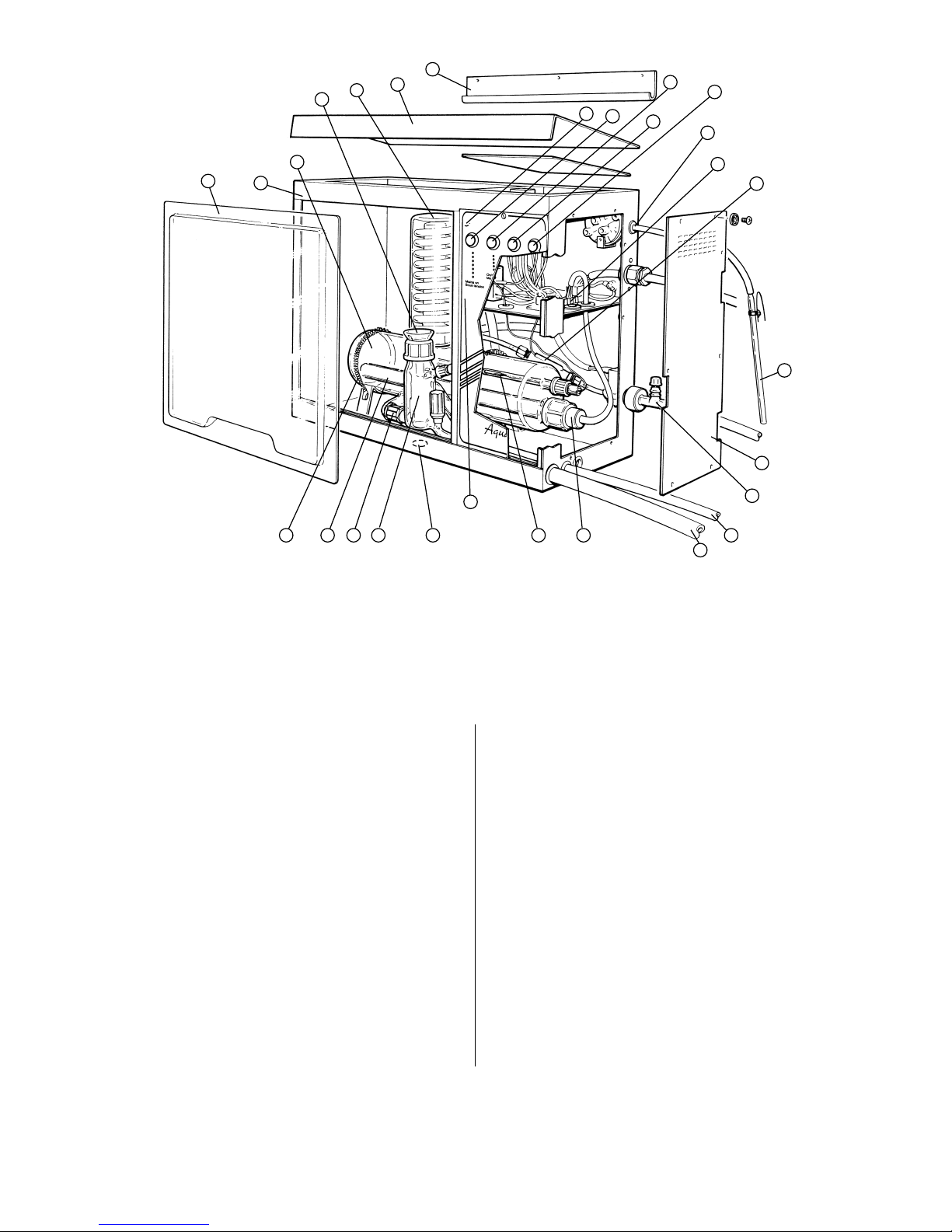
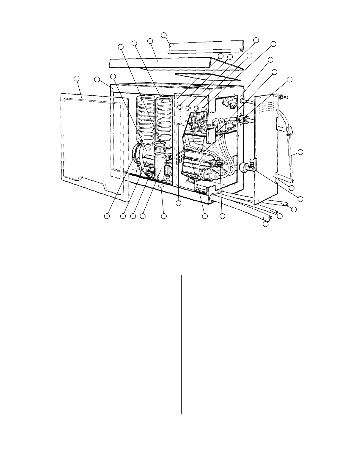
–the Rotaflo stopcock on the boiler
level control WL48 is closed.
–the Reservoir pressure switch is
fitted to the distillate collection
vessel.
–the dummy shorting plug is fitted
to socket item 8, fig. 1.
3Switch on the electricity supply – the
green indicator light will illuminate.
4Press the ON/OFF switch to the ON
position – the switch will illuminate.
5Recheck that the CLEAN switch is in
the CLEAN position and illuminated.
6Turn on the mains water supply and
using the needle valve item 18 fig. 1
on the side of the cabinet, adjust the
flow rate to approximately 1 litre/min.
Check that there are no water leaks
from the hose connections.
7Observe that the boiler is now filling
with water to cover the heating
element. When the water has reached
the pre-set level, the excess will be
discharged to drain. Check that the
drain water flows freely and does not
“back-up” into the level control.
8Switch the CLEAN button off by
pressing it for a second time – the
switch light goes out.
The heater will start to warm up and
eventually run at a red glow. If the
flow rate is insufficient, then the
heater will not switch on – this will
require the control needle valve to be
opened further. After about 2 to 3
mins. of operation distilled water will
emerge from the outlet pipe, falling
into the collection reservoir.
9To avoid excessive wastage of coolant
water, make further adjustments to
the needle valve. Slowly reduce the
flow-rate until the flow control switch,
item 15, switches off the heaters –
then increase the flow until the power
is restored.
10 Refit the perspex viewing screen.
11 Safety Cut-Outs
All Aquatron water stills are protected
by the following safety devices.
Flow Control Switch (item 15)
monitors the flow of coolant water
into the still and shuts off the heating
element, if the flow is insufficient.
Thermostat Cut-Out (item 22)
In normal operation the water within
the glass will be at 100°C. In single
fault conditions, i.e. in the event of
water supply failure, the content will
increase to 110°C where upon a
resettable thermostat will operate.
Once switched, the thermostat has to
be manually reset. This is achieved by
unscrewing the black knob, fig. 1,
item 23, located inside the cabinet
and pressing the reset button.
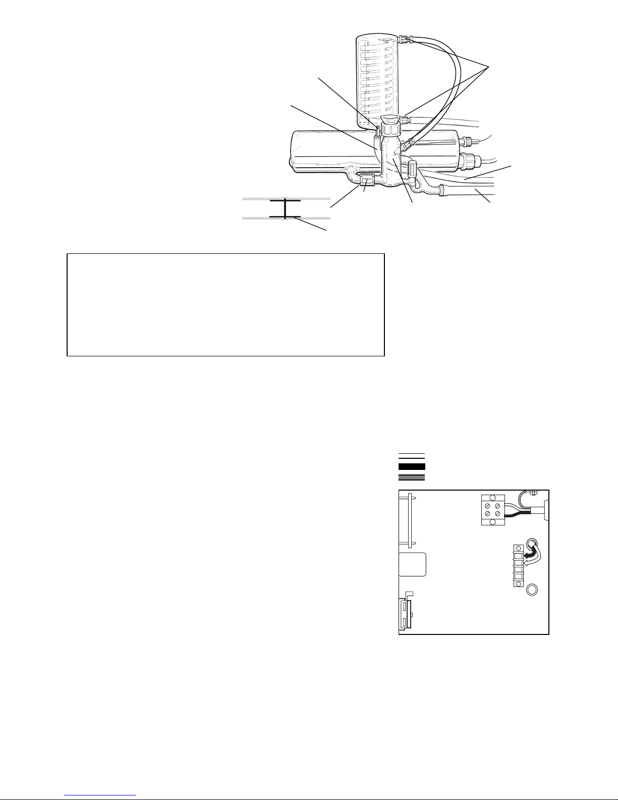
Reservoir Control (fig. 11)
is positioned on the collection
reservoir and switches off both the
electricity and water supply when the
reservoir is full of distilled water. The
water supply is only shut off around 7
minutes after the reservoir is full to
allow the heating element to cool.
It is recommended that the operation
of the flow switch and reservoir
control be checked on a regular basis.
a) Simulation of Mains Water
Supply Failure
Turn off the mains water supply at
the tap. This should switch off the
heating element. Turning the tap on
again will switch the heater on.
b) Simulation of Reservoir Full
Condition
Lower the glass pressure bell WPB,
(fig. 11), into the distillate to a
depth of 150mm. This will switch
off the heating element
immediately and the cooling water
after 7 minutes. Raising the bell will
cause both to be re-supplied.
12 Switching Off
Push the CLEAN switch to the ON
position. Wait until the residual heat
contained in the heating element has
dispersed and no boiling is evident.
Turn off water supply. Push ON/OFF
switch to OFF position. Isolate from
mains electricity supply.