Bike-Lift SA-07 User manual

Operating manual No. 057-2-6-0009-R0 Page 1
Version 2018
EN
EC Use and Maintenance Manual
SA-07 Shock absorber dismantler
Bike
BikeBike
Bike-
--
-Lift EUROPE s.r.l.
Lift EUROPE s.r.l. Lift EUROPE s.r.l.
Lift EUROPE s.r.l.
via Don Milani, 40/42
43012 anguinaro di Fontanellato (PARMA) – Italy
Web site: www.bikelifteurope.it
E-mail: info@bikelifteurope.it
Operating manual No. 057-2-6-0009-R0 Page 2
Version 2018
EN
Summary
1 Information section ............................................................................................................................. 4
1.1 Preface ................................................................................................................................................ 4
1.2 Prohibitions ........................................................................................................................................ 5
1.3 Warranty ............................................................................................................................................. 5
Warranty conditions ................................................................................................................... 5
1.3.1
Insurance .................................................................................................................................... 5
1.3.2
1.4 Manufacturer identification ............................................................................................................... 6
1.5 Technical assistance and spare parts ................................................................................................. 6
1.6 C Declaration of conformity ............................................................................................................. 7
1.7 Normative references ......................................................................................................................... 8
1.8 General regulations and conventions................................................................................................. 8
1.9 Key ...................................................................................................................................................... 9
2 Machine description ................................................................................................................... 10
2.1 Machine name .................................................................................................................................. 10
2.2 Shock Absorber Dismantler identification ........................................................................................ 10
2.3 Intended use and reasonably foreseeable misuse ........................................................................... 11
2.4 Technical specifications .................................................................................................................... 11
Standard adapters data ............................................................................................................ 11
2.4.1
3 Safety section .................................................................................................................................... 12
3.1 nvironmental working values ......................................................................................................... 12
3.2 Sound level ....................................................................................................................................... 12
3.3 Operator protections ......................................................................................................................... 12
3.4 Pictograms ........................................................................................................................................ 12
3.5 General safety rules .......................................................................................................................... 13
4 Transport and handling section ...................................................................................................... 14
4.1 Transport, handling and storage ...................................................................................................... 14
4.2 Unpacking ......................................................................................................................................... 14
4.3 Disposal of the packaging ................................................................................................................. 14
4.4 Packaging and transport ................................................................................................................... 15
4.5 Warnings for handling and transport ............................................................................................... 15
5 Installation section .......................................................................................................................... 16
5.1 Filling ............................................................................................................................................... 17
Operating manual No. 057-2-6-0009-R0 Page 3
Version 2018
EN
6 Dismantling/scrapping section ........................................................................................................ 18
6.1 Storage .............................................................................................................................................. 18
6.2 Scrapping and disposal ..................................................................................................................... 18
6.3 Scrapping materials .......................................................................................................................... 18
6.4 Instructions for a suitable waste treatment ....................................................................................... 18
6.5 lectrical and electronic equipment waste ...................................................................................... 19
7 Operation section ............................................................................................................................. 20
7.1 Use .................................................................................................................................................... 21
8 Maintenance section ........................................................................................................................ 23
8.1 Maintenance ..................................................................................................................................... 23
8.2 Cleaning ............................................................................................................................................ 23
Cleaning of the work areas ....................................................................................................... 23
8.2.1
8.3 Problems and remedies .................................................................................................................... 24
9 Technical diagrams and components section .................................................................................. 25
Machine maintenance sheet ........................................................................................................................... 26

Operating manual No. 057-2-6-0009-R0 Page 4
Version 2018
EN
1 Information section
1.1 Preface
The EC Use and Maintenance Manual is a document issued by Bike-Lift Europe s.r.l. as an
integral part of the Machine.
The purpose of this publication is to provide the operator with efficient and safe instructions
regarding the use and maintenance.
This Manual must be read entirely before starting any operation concerning the
installation, use, maintenance and putting out of service of the machine; therefore it
is necessary to be kept intact over time.
In order to properly store the Manual it is recommended to:
•
Use the manual without deteriorating it;
•
Do not remove, add, change or rewrite any part of the Manual; any modifications must
be made only by Bike-Lift-Europe s.r.l.;
•
Keep the Manual in areas protected against humidity in order not to compromise its
durability over time;
•
Deliver the Manual to any other user or subsequent owner of the Machine.
Workers in charge of using this machine must have all the necessary information and
must receive proper training.
The manual and relative documentation are confidential by law with the prohibition of
reproduction or transmission to third parties without receiving the explicit authorization of the
manufacturer.
As a partial exception to the above mentioned, a copy of this Manual kept in the vicinity of the
Machine is allowed for prompt reference, in case the original document is stored in a different
place, in order to guarantee better keeping over time.
Drawings, data and specifications contained in this manual can be modified at any time by the
company, without prior notice.
In case of significant changes of the machine due to the installation of new parts, Bike-Lift
Europe s.r.l. will compile an updated Manual that will be sent to the Customer together with
the purchased part.

Operating manual No. 057-2-6-0009-R0 Page 5
Version 2018
EN
1.2 Prohibitions
The installation, use, maintenance and putting out of service of the device with means, objects,
actions and anything else not provided for in this manual is considered improper and therefore
the manufacturer declines all responsibility for the consequences that may occur regarding
people, animals and objects.
It is expressly FORBIDDEN the use of the Machine by Operators who do not
know the regulation and procedures described in the Manual and by unauthorized
people (hereinafter referred to as "non-operators").
It is also forbidden the use of the machine by children and the non-operators or children must
not stand near the machine during all phases of the machine's life.
The putting out of service of the protection systems or anything else provided by the
manufacturer to protect the operators is the sole responsibility of the Purchaser or the
Machine's User.
Any mechanical, electrical or functional change of the Machine (not provided for in this
Manual) regarding the control systems, the logic of controls, the circuits present and the safety
systems is prohibited without the prior written authorization of the manufacturer.
1.3 Warranty
Bike-Lift Europe s.r.l. will not be held responsible for inconveniences, breakages, accidents,
etc. due to lack of knowledge or failure to apply the procedures specified in this Manual. The
same applies to the execution of modifications, changes or for the installation of accessories
not previously authorized.
Warranty conditions
1.3.1
Bike-Lift Europe s.r.l guarantees its products for 12 months, except for the commercial
components that are guaranteed by the manufacturers.
All worn parts are excluded from the warranty.
The warranty is limited to the replacement, ex-works Bike-Lift Europe s.r.l, of those parts that
are recognized as defective by Bike-Lift Europe s.r.l due to a material or manufacturing defect
and do not include labor or travel expenses required for their replacement.
The recognition of the warranty is void if the anomaly is due to an inappropriate use of the
product, if the installation was not carried out according to the provisions of the company or if
non-genuine parts were installed.
It also becomes void if the product has been submitted to performances exceeding those
indicated by Bike-Lift Europe s.r.l.
Insurance
1.3.2
All Bike-Lift Europe s.r.l products are insured with an RCP policy with a price ceiling of €
3.000.000. Damages caused by negligence or tampering are excluded.

Operating manual No. 057-2-6-0009-R0 Page 6
Version 2018
EN
1.4 anufacturer identification
Bike-Lift EUROPE s.r.l. via Don Milani, 40/42, 43012 Sanguinaro di Fontanellato (PARMA)
– Italy
Website: www.bikelifteurope.it
E-mail:
info@bikelifteurope.it
Tel: 0039-0521-827091
Fax: 0039-0521-827064
1.5 Technical assistance and spare parts
To order spare parts, it is recommended to specify exactly the following data:
•
Model and serial number of the machine;
•
Code number and part name;
•
Required quantity;
•
Shipping means, address and telephone number;
For replacements use only genuine spare parts.
Do not wait until the components are completely worn before replacing them.
CAUTION: THE RECIPIENT WILL BE CHARGED FOR THE REPLACEMENT
TOGETHER WITH THE SHIPPING COSTS.
We recommend that you always contact Bike-Lift Europe s.r.l. for all those Assistance and
maintenance operations that are not described or indicated in this Manual.

Operating manual No. 057-2-6-0009-R0 Page 7
Version 2018
EN
1.6 EC Declaration of conformity
I FR B D E NL
Dichiarazione di
conformità
Declaration de
conformité
Declaration of
conformity
Konformitäts
-
erklärung
Declaración de
conformidad
Declaratie van
conformiteit
Io sottoscritto Je soussigné The undersigned
Der
Unterzeichnete
im name der
l abajo firmante
Ondergetekende
Bike-Lift EUROPE s.r.l. via Don Milani, 40/42, 43012 Sanguinaro di Fontanellato (PARMA) –
Italy
Dichiara sotto la
propria
responsabilità,
che la smonta
ammortizzatori
Déclare sous sa
propre
responsabilité
que la machine
Declares under its
own
responsibility
that the machine
rklärt auf eigene
Verantwortung
dass die
Maschine
Declara bajo su
responsabilidad
que la máquina
Verklaart op eigen
verantwoordelijkh
eid dat de machine
Marca
Marque
Trademark
Marke
Marca
Merk
Modello:
Modèle:
Model:
Modell:
Modelo:
Model:
Numero di serie
Numéro de
série
Serial number
Serien Nummer
Numero de serie
Serienummer
Conforme alla
direttiva
st conforme
aux
spécifications
de la directive
Complies with the
requirements
established by
directive
Die
Bestimmungen
des rlasses
Cumple los
requisites de la
directiva
Overeenkomt met
het gestelde in
MD 2006/42/CE
successive
modifiche ed
integrazioni,
secondo le
norme
et compris les
modifications et
les intégrations,
selon la norme
And subsequent
modifications and
supplements,
according to
standard
Und den
nachfolgenden
Änderungen
entspricht,
entsprechend den
Richtlinien
Y succesivas
modificacions e
integracions,
según la norma
n aanvullingen en
modificaties
hiervan, volgens
richtlijn
EN ISO 12100:2010; EN 349; EN 982
Bike Lift urope
s.r.l
Alessandro Tozzi

Operating manual No. 057-2-6-0009-R0 Page 8
Version 2018
EN
1.7 Normative references
The machine is identified by the CE marking drawn up according to the specifications of the
Machinery Directive 2006/42/EC and subsequent updates.
Reference
Title
2006/42/EC
Machinery Safety Directive
EN ISO 12100 (2010)
Safety of machinery - General principles of design - Risk
assessment and risk reduction.
UNI EN 349 (1993+A1:
2008)
Safety of machinery - Minimum spaces to avoid the crushing
of body parts.
EN 982 (2009)
Safety of machinery - Safety requirements related to systems
and their components for hydraulic fluid and pneumatic
transmissions - Hydraulic fluid
UNI 1285-68
Calculation of metal pipes resistance subject to internal
pressure
1.8 General regulations and conventions
This manual is an integral part of the product and MUST be kept for further reference.
FOR ANY REQUEST FOR CLARIFICATION, CONTACT THE EMPLOYER OR THE
BIKE-LIFT EUROPE S.R.L TECHNICAL SERVICE, AVOIDING PERSONAL
INITIATIVES THAT COULD CAUSE VERY SERIOUS OR FATAL ACCIDENTS.
Read the warranty carefully before using the machine.
CONVENTIONS:
In this manual "right side", "left side", "forward", "backwards", "top" and "bottom"
refer to the operator located in front of the machine with the hydraulic pump on his right
side.
In this manual the measurement units are expressed in the SI international system (e.g.
the capacity of liquids is expressed in liters).

Operating manual No. 057-2-6-0009-R0 Page 9
Version 2018
EN
1.9 Key
SHOCK ABSORBER DISMANTLER: spring compression system for the replacement of
shock absorbers and fork gaskets.
OPERATOR: In compliance with Directive 2006/42/EC and subsequent updates, it is specified
that the term "operator" means the person (s) in charge of installing, operating, adjusting and
cleaning the machine. The maintenance and repair operations of the machine are the
responsibility of competent personnel.
SYMBOLS
MEANIN
Yellow triangle pictogram generally indicates a Warning /Risk, e.g. risk of high
temperatures, risk of crushing the hands, ...
BLUE round pictogram generally indicates an Obligation, for example the
obligation to wear certain PPE (goggles ...) or the Obligation to read the User
Manual.
Round red Prohibition pictogram indicates in general a Prohibition, for example,
person access prohibition, prohibition of hand access while the vehicle is moving.
Indicates that the operation can be performed by specialized personnel authorized
by the Employer.
Particular importance indication that requires attention.
Specifies an operation that can only be performed by trained personnel, or after
having read and consulted specific operating instructions.
Operating manual No. 057-2-6-0009-R0 Page 10
Version 2018
EN
2 Machine description
2.1 achine name
The Shock Absorber Dismantler described in this manual has been specifically designed for
use in the dismantling and assembly operations of shock absorbers and gaskets for motorcycle
forks.
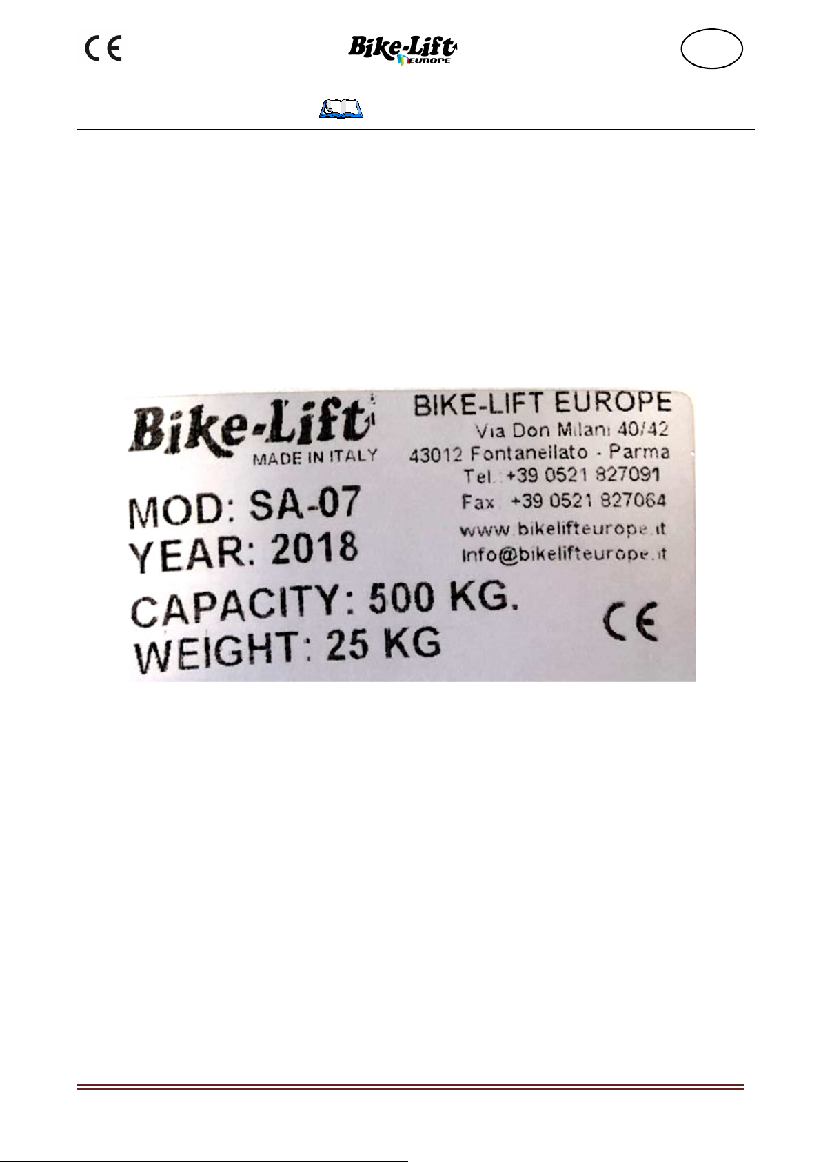
2.2 Shock Absorber Dismantler identification
The machine has an identification plate fixed in a visible way as indicated in the following
picture.
Figure 1- example of a plate affixed to the machine
Refer to these details for ordering spare parts and for any kind of contact with the manufacturer
It is absolutely forbidden for the user to remove or alter this plate. Any modification or
removal of the plate will void any warranty.
The machines can be subject to updates or small aesthetic changes and therefore have different
details than those shown, without prejudice to the descriptions and procedures contained by
this Manual.

Operating manual No. 057-2-6-0009-R0 Page 11
Version 2018
EN
2.3 Intended use and reasonably foreseeable misuse
The shock absorber dismantler is intended exclusively for disassembly and/or assembly of
shock absorbers and/or gaskets for motorcycle forks.
The following operations are not permitted:
• use for industrial shock absorbers is prohibited
• use in potentially explosive atmospheres environments is forbidden
• it is forbidden to use the device for applications other than those indicated
THIS MACHINE IS DESIGNED ONLY FOR THE INTENDED USE
DESCRIBED IN THIS MANUAL; ANY OTHER USE IS TO BE
CONSIDERED IMPROPER AND THEREFORE THE MANUFACTURER
CANNOT BE HELD LIABLE FOR ANY DAMAGES CAUSED BY USE
CONSIDERED INAPPROPRIATE OR NOT EXPRESSLY MENTIONED IN
THIS USER MANUAL.
THE MACHINE IS DESIGNED EXCLUSIVELY FOR SINGLE
OPERATOR USE
2.4 Technical specifications
Model
SA 07
Weight
Kg
15
General sizes mm
length "L"
height "H"
depth “D”
210 mm
1040 mm
245 mm
Standard adapters data
2.4.1
Diameter
Diameter
Diameter
45 mm
59 mm
75 mm
47 mm
62 mm
77 mm
50 mm
66 mm
80 mm
53 mm
68 mm
83 mm
56 mm
71 mm
87 mm
Operating manual No. 057-2-6-0009-R0 Page 12
Version 2018
EN
3 Safety section
3.1 Environmental working values
The use environment of the machine must be well lit, must not present explosion hazards of
any kind and must be protected from atmospheric precipitations.
The machine works properly within the following values:
•
Ambient temperature between 5° and 40° C;
•
Ambient humidity between 30% and 90% without condensation;
STORAGE: if the machine has been unpacked, store it in a closed space protected from bad
weather conditions.
3.2 Sound level
During the normal conditions of use some measurements were made at the workplace at a
distance of 1 meter and at a height of 1.6 meters above the ground.
The survey was carried out with a sound level meter, complying with IEC 651 standard, class 1
and the result of the assessment was lower than the minimum limit of action required by the
regulations in force.
3.3 Operator protections
Before starting any type of work using the shock absorber dismantler, the
operator must wear appropriate personal protective equipment (PPE),
such as gloves and safety footwear.
Always wear work clothing normally used in the mechanical workshop
activity.
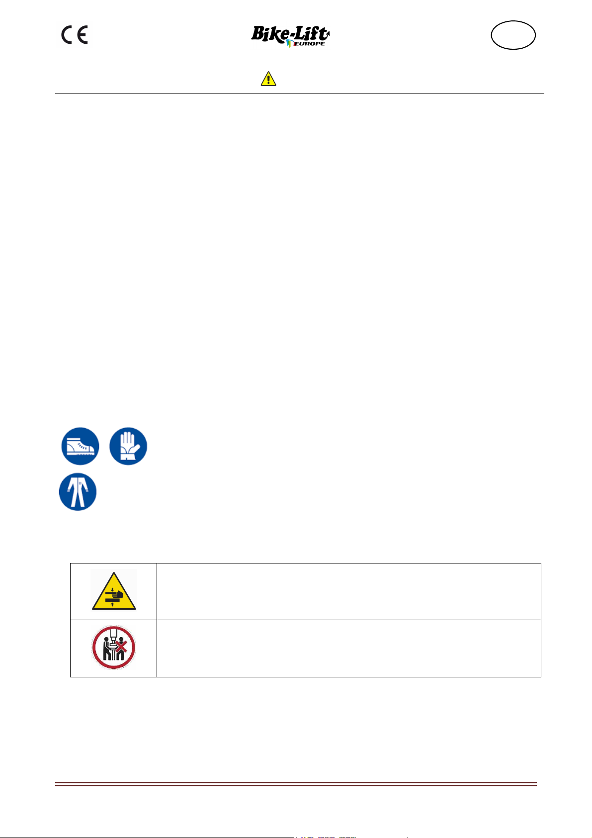
3.4 Pictograms
Hands crushing hazard.
The machine must always be operated by only one Operator
Operating manual No. 057-2-6-0009-R0 Page 13
Version 2018
EN
3.5 General safety rules
•
The shock absorber dismantler must only be operated by trained and authorized
personnel.
•
Before using the shock absorber dismantler, check that it has not been damaged, that
there are no air leaks or worn parts.
•
Do not overload the shock absorber dismantler. Overloading can damage or break the
shock absorber dismantler.
•
Make sure that the brackets have been positioned and fixed correctly depending on the
spring to be disassembled.
•
Periodically carry out a complete check of the shock absorber dismantler, making sure
that each of its components is intact and fully functional.
ACCURATE USE OF THE SHOCK ABSORBER DISMANTLER:
•
Do not subject the shock absorber dismantler to overloads; always check the integrity of
the machine.
•
Make sure that the spring is correctly held in the respective bracket so as to avoid any
sudden slippage.
•
Do not allow the shock absorber dismantler to be used by people who have not read
these instructions.
•
The shock absorber dismantler must not be modified. Modifications can reduce or
cancel the effectiveness of security measures and increase risks for the operator.
•
Carefully check the shock absorber dismantler, making sure that the moving parts of the
machine work perfectly, that they do not jam and there are no broken or damaged parts
that could jeopardize their operation.
•
Have the shock absorber repaired only and exclusively by specialized personnel and
only using genuine spare parts.
•
Remove the dirt and dust accumulated on the sliding parts (column) with a dry cloth,
every 200 cycles of use or about every 3 months.
The machine must always be operated by only one Operator.
THE MANUFACTURER DECLINES ANY RESPONSIBILITY FOR DAMAGES TO
THINGS OR PEOPLE CAUSED BY FAILURE TO COMPLY WITH THE SAFETY
REGULATIONS DESCRIBED IN THIS MANUAL, INCLUDING THE LAWS IN FORCE
AT THE WORKPLACE.
IT IS EXTREMELY IMPORTANT THAT THE OPERATOR UNDERSTANDS ALL THE
SAFETY RULES LISTED BELOW IN ORDER TO AVOID PERSONAL INJURY OR
DAMAGE TO PROPERTY OR THE OTHERS.
A machine that is not subject to regular maintenance is a hazard source to the operator and to
people working nearby. To ensure the safe and efficient operation of the machine, make sure
that the maintenance schedule is correctly followed.
It is strictly forbidden to tamper with, modify or change the parts of the machine that will
alter its regular operation.

Operating manual No. 057-2-6-0009-R0 Page 14
Version 2018
EN
4 Transport and handling section
4.1 Transport, handling and storage
CAUTION: Disseminate the instructions described in this chapter to all personnel
involved in the transport and handling of the machine.
For safety reasons, the moving parts must be locked before transport.
4.2 Unpacking
If the machine is supplied wrapped in nylon cloth, any accessories, spare parts and
consumables will be packed in cardboard boxes and positioned above the work surface.
To remove the packaging, cut the nylon tape, taking care not to damage the machine or its
parts.
Remove any accessories located above the work surface, and make sure that the contents
comply with the order and the accompanying documentation.
4.3 Disposal of the packaging
N.B.
Disposal of the packaging must be done by the purchaser in compliance with the laws in
force.
N.B.
The components of the packaging (e.g. cardboard, plastic, polystyrene, nails, nylon, etc.)
MUST NOT be left within the reach of children, as they are a source of hazard.
NO COMPLAINTS WILL BE ACCEPTED IF THE GOODS DO NOT COMPLY WITH
THE ORDER OR THE ACCOMPANYING DOCUMENTS IF THEY ARE NOT
REPORTED WITHIN FIVE DAYS FROM THE RECEIPT DATE OF THE GOODS.

Operating manual No. 057-2-6-0009-R0 Page 15
Version 2018
EN
4.4 Packaging and transport
You can manually handle the packaged machine, as previously described (see section 4.2), but
it is recommended to use lifting means such as a pallet jack whose maximum lifting capacity
must not be less than the total weight of the shock absorber dismantler.
N.B. THE TOTAL WEIGHT OF THE MACHINE IS SHOWN ON THE IDENTIFICATION
PLATE AFFIXED TO THE MACHINE.
The machine is tested and in perfect condition.
4.5 Warnings for handling and transport
The loading or unloading is recommended to be carried out manually or using lifting
equipment (e.g. pallet jack). Also take into account:
•
It is strictly forbidden for things and/or people to be near the machine, the unloading or
loading area and the means of transport during the loading and unloading operations.
•
Do not carry out sudden maneuvers when lifting or lowering the load.
•
Pay the utmost attention during all handling operations, to make sure that the machine
will not be damaged.
•
Follow the internal and legal provisions concerning lifting and transport.
•
IT IS FORBIDDEN TO APPROACH OR PASS UNDER SUSPENDED LOADS.
N.B. THE MANUFACTURER DECLINES ALL RESPONSIBILITY FOR ANY DAMAGE
CAUSED BY ANY ACTION DURING THE UNLOADING, LOADING AND HANDLING
OPERATIONS OF THE MACHINE.

Operating manual No. 057-2-6-0009-R0 Page 16
Version 2018
EN
5 Installation section
The machine must be installed in compliance with the safety regulations and instructions
included in this chapter. The machine must be positioned in such a way as to allow the
Operator to easily replace the shock absorbers or the gaskets of the bike fork.
The shock absorber dismantler must therefore be installed by taking into account the minimum
distances from walls or other possible boundaries (boundaries are imaginary lines that delimit
the work or safety areas of other machines or structures).
Simple precautions are necessary for the positioning of the shock absorber dismantler.
Always consider the safety aspect not only in relation to the work performed with the machine
but also to the hazards caused by other machines present in the workplace.
Before positioning the machine make sure that:
•
The flooring is suitable for placing the machine, i.e. without holes, yielding parts, and
its capacity is sufficient to support the weight of the press plus the weight of the
accessory parts and any large work piece, considering an adequate safety factor.
•
If the positioning must be performed on lofts, upper floors or elevated areas, make sure
that the maximum capacity of the lofts or flooring is higher than the weight of the
machine and any accessory weights, considering also an adequate safety factor.
•
Do not place the machine on yielding or non-compact surfaces (e.g. on gravel or
crushed stone, sand, etc.).
•
PAY CLOSE ATTENTION TO THE OVERHEAD POWER LINES.
•
Check in advance the position of any overhead power line and signal them with
appropriate warning signs.
•
Always consider an adequate distance from the sliding ways of the means of transport,
elevators, pallet jacks, etc. Sources of unpredictable and sudden hazard.
•
Make sure that the identified position is always equipped with adequate lifting systems.
•
Pay the utmost attention to the handling of lifting systems (e.g. gantry cranes, hoists,
pallet jacks, forklift trucks, cranes, jib cranes, etc.)

Operating manual No. 057-2-6-0009-R0 Page 17
Version 2018
EN
5.1 Filling
N.B. When the oil level in the tank drops, generally following:
volume absorption by the cylinder
volume absorption by the system
the discharge of air bubbles left in the pipes
it is necessary to fill up the oil level by bringing it to the correct level and checking it with the
level indicator.
Operating manual No. 057-2-6-0009-R0 Page 18
Version 2018
EN
6 Dismantling/scrapping section
6.1 Storage
In case of prolonged storage, protect the machine from rain and wind and possibly store it in a
dry place.
Protect the electrical parts from dust and external agents.
The machine can be seriously damaged if, while pending for the installation, it is kept in a
critical temperature environment. Do not expose the machine to temperatures below -10° C or
above + 60° C.
It is forbidden to store the machine or its parts on structures that have not
been specially designed
It is forbidden to store material or equipment on the machine
6.2 Scrapping and disposal
To dismantle the machine, proceed according to the following general disassembly procedure:
•
Empty the tanks of the hydraulic system.
•
Disconnect the mechanical parts.
WARNING: When handling waste it is necessary to have the appropriate
Personal Protective Equipment
6.3 Scrapping materials
These are non-hazardous special waste that can be recovered, according to M.D. of February
5
th
, 1998:
•
Ferrous materials, aluminum, stainless steel, copper
•
Plastic materials
•
Hydraulic oil
6.4 Instructions for a suitable waste treatment
Proper management of special waste includes:
Storage in suitable locations avoiding the mixing of hazardous and non-hazardous waste.
Make sure that the transport and disposal/recovery of the waste is done by authorized carriers
and recipients.
The transport of waste to authorized collection centers is allowed only if you are registered at
the Environmental Managers Register.

Operating manual No. 057-2-6-0009-R0 Page 19
Version 2018
EN
6.5
Electrical and electronic equipment waste
According Legislative Decree no. 151 of 25
th
of July 2005, the Italian Government has
implemented the European Parliament directives on the disposal of electrical and electronic
equipment waste (WEEE) (Directive 2002/95/EC and 2003/108/EC).
The decree specifically establishes measures and procedures aimed to:
1.
prevent WEEE production;
2.
promote reuse, recycling and other ways of WEEE recovery, in order to reduce the
amount to be disposed of;
3.
improve, from an environmental point of view, the intervention of the subjects
participating in the life cycle of these devices (producers, distributors, consumers and
operators directly involved in the WEEE treatment);
4.
reduce the use of hazardous substances in electrical and electronic equipment.
The decree requires the limitation and elimination of some substances present in WEEE:
banned lead, mercury, cadmium, hexavalent chromium, polybrominated biphenyls and
polybrominated diphenyl.
The machine has been designed and manufactured in compliance with this directive. Follow
the instructions below.
This symbol, showing a crossed-out garbage wheeled bin, indicates the
separate collection of electrical and electronic equipment of the machine.
The user of this machine may contact the collection centers set up by the
Municipalities or ask for waste collection by the retailer, in order to dispose
of it correctly.

Operating manual No. 057-2-6-0009-R0 Page 20
Version 2018
EN
7Operation section
Before starting any maneuver, make sure that there are no other people in the immediate
vicinity of the machine.
Before starting to use the shock absorber dismantler, make sure that it has been well fixed to
the ground using the four holes in the base of the structure (Figure 2-holes in the base of the
structure
)
Check the correct operation of the shock absorber dismantler by carrying out a series of
maneuvers with no load, using the control lever.
The shock absorber dismantler is equipped with a safety hook; in order to carry out
any type of maneuver by using the control lever, it must be tightened to the ferrule
located on the back of the hook, by screwing the ferrule in order to activate the
pneumatic safety system.
Figure 2-holes in the base of the structure
Table of contents
Other Bike-Lift Lifting System manuals

Bike-Lift
Bike-Lift Master 504 Gate User manual

Bike-Lift
Bike-Lift LEVANTE-50 User manual

Bike-Lift
Bike-Lift Racing 350 Operator's manual

Bike-Lift
Bike-Lift HQL 400 User manual

Bike-Lift
Bike-Lift Racing 350 User manual

Bike-Lift
Bike-Lift PSB-20 User manual

Bike-Lift
Bike-Lift Kodiak 500 User manual

Bike-Lift
Bike-Lift Master 504 User manual

Bike-Lift
Bike-Lift CFL-500 User manual
Popular Lifting System manuals by other brands


MW TOOLS
MW TOOLS SL300U manual

ShoreStation
ShoreStation Manual SSV50108MS manual

Titan Lifts
Titan Lifts HD2P-10000AC-D Installation, operation & maintenance manual

Mec
Mec TITAN Boom 40-S Operator's manual

probst
probst VZ-I operating instructions

HADEF
HADEF 147/05 Installation, Operating and Maintenance Instruction