5
CHAPTER 3: Installation
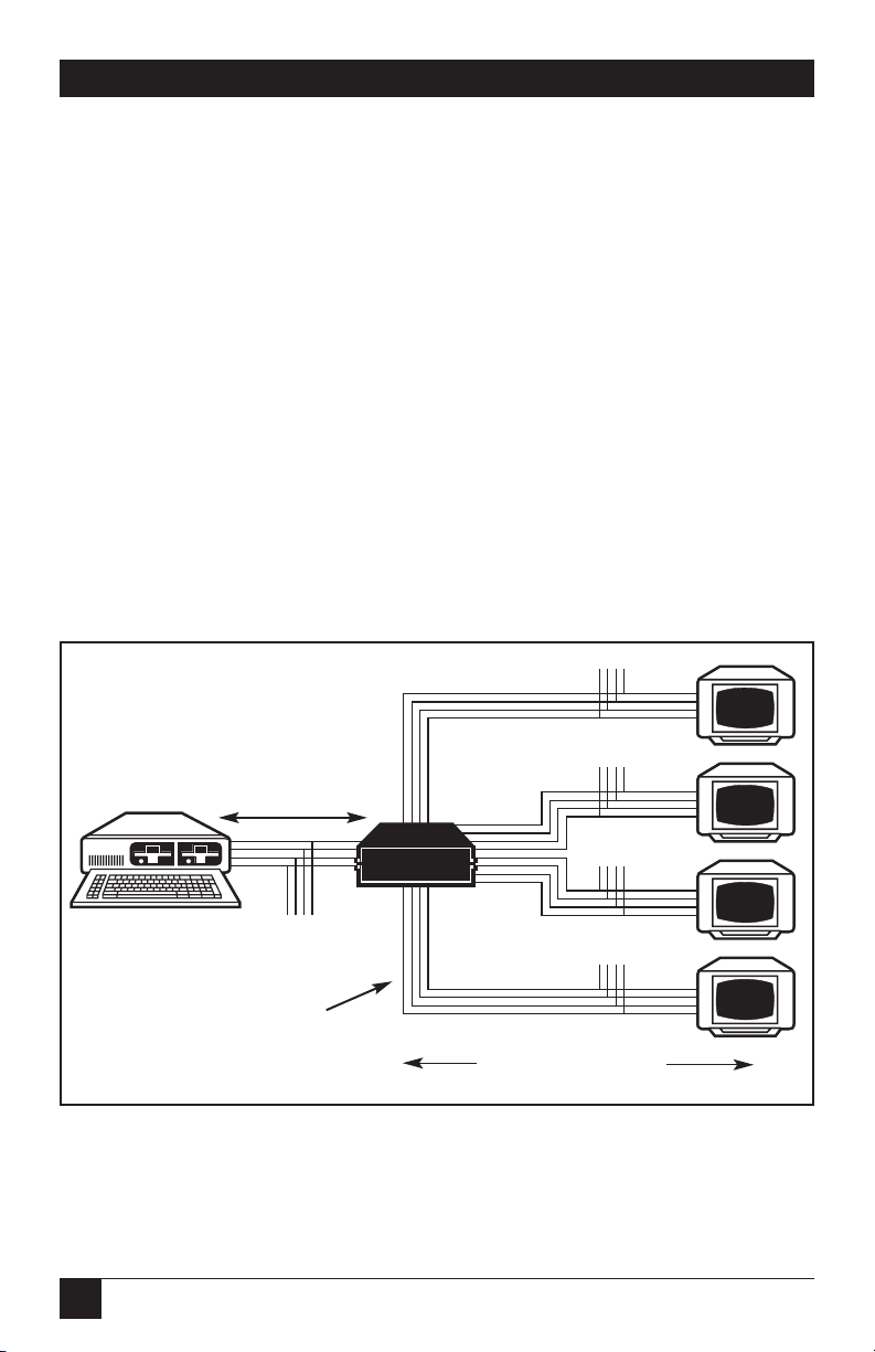
1. Locate the Splitter within 6 feet (1.8 m) of the computer’s RGBS video-
output port. Connect the computer’s video output to the Splitter’s inputs,
Red to Red, Green to Green, Blue to Blue, and Sync to Sync. (See Figure 1
on the previous page.)
NOTE
The RGBS Video Splitters also support RGB video with sync on green.
Call our technical support personnel for help with your application.
RGBS Video Splitters cannot be cascaded.
2. Connect the Splitter’s output ports to the display devices’ RGBS inputs,
Red to Red, Green to Green, etc., as in Step 1. Each monitor can be
located up to 350 feet (105 m) from the Splitter’s output.
Cabling Notes:
•Four coaxial cables are required for each device connected to the
Splitter: one for each of the color signals (Red, Green and Blue)
and one for the sync (S) signal (see Figure 2-1 on the previous page).
Note, however, that our EYNRGBS2 cable bundles these four cables
into one easy-to-work-with jacket.
• All cable ends connected to the Splitter must be terminated with BNC
coaxial male connectors.
• The RGBS Video Splitter has been designed to drive signals through
75-ohm RG59/U coaxial cables. (See the Appendix for the RGBS
coaxial cables we offer.)
3. Connect the power supply to the Splitter by inserting the power supply’s
5-pin DIN output plug into the connector marked “Power” on the back
of the unit. Then plug the power supply into an outlet providing stable
AC power.
After these steps are completed, the system is ready to operate. The Splitter
can remain powered-up continuously. There is no need to disconnect the
unit between uses, unless you are moving your setup.
3. Installation