Page 3
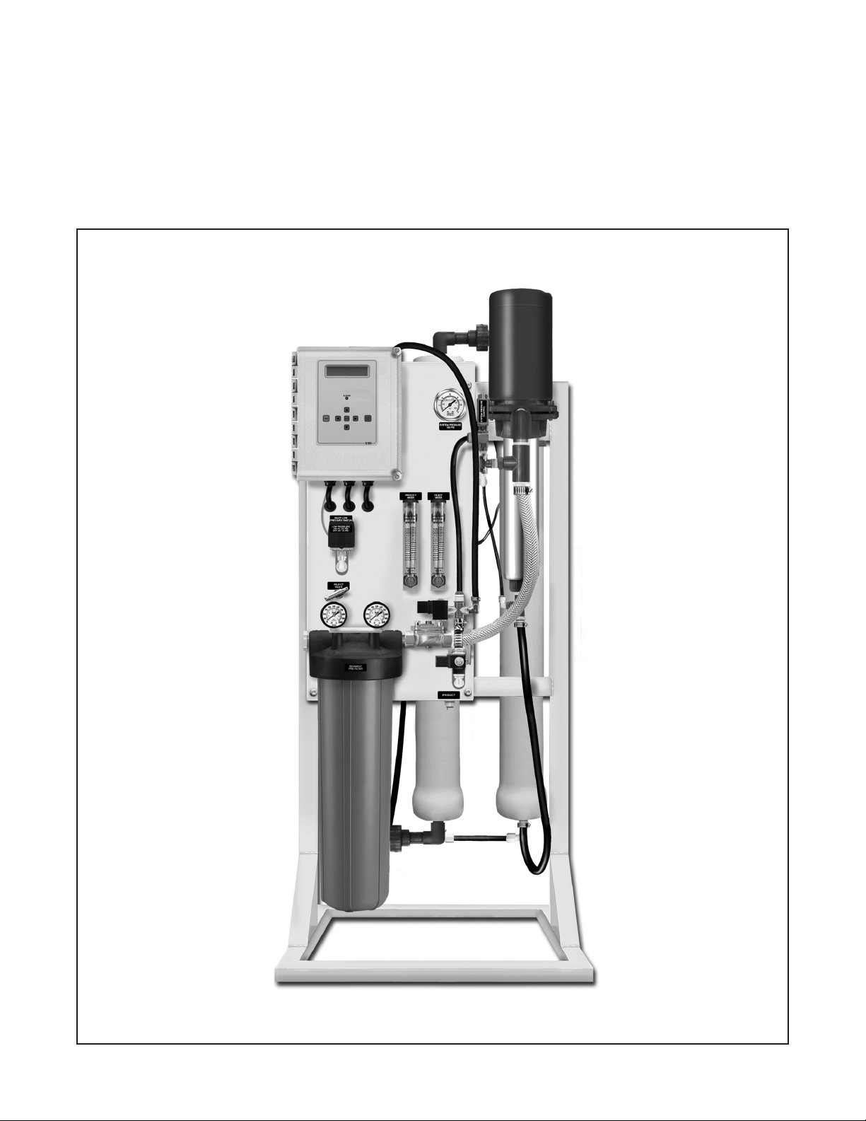
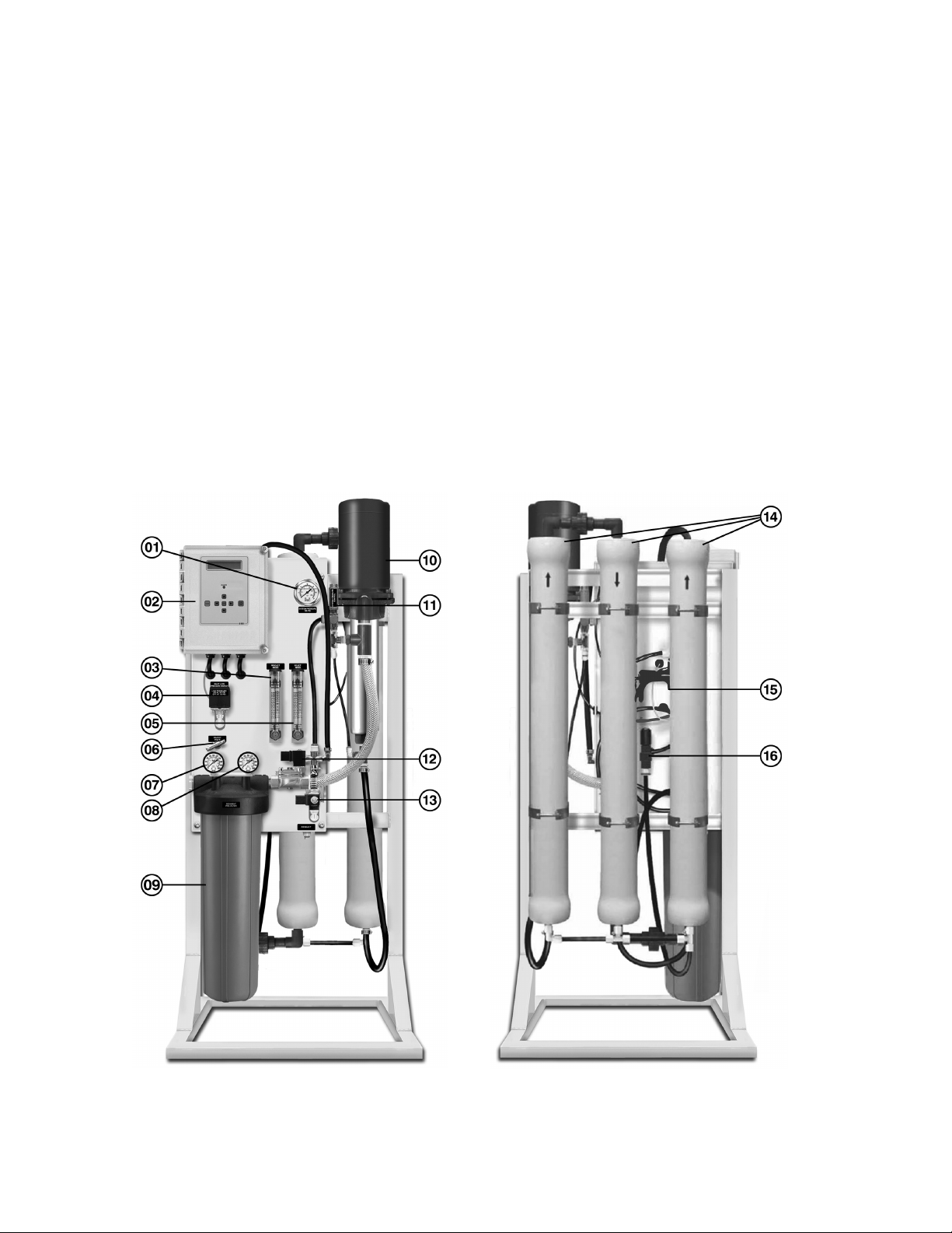
BLS Reverse Osmosis System
Introduction
Your BLS Reverse Osmosis System has been designed to
produce quality water for a variety of applications. We are
condent that you will nd BLS Systems provide quick and
simple installation, hassle-free maintenance, and years of
reliable and trouble-free operation.
BLS RO Systems incorporate years of engineering
experience, dedicated workmanship, and quality
manufactured components. Each system is built with pride
and is factory tested for superior performance.
As with all products, the customer has the responsibility to
ensure that the BLS RO System is operated under proper
conditions and within design limitations. All installation,
startup, and maintenance instructions must be followed
carefully.
HOW REVERSE OSMOSIS WORKS
In the reverse osmosis process, water is forced under
pressure through a semipermeable membrane to reduce
the dissolved mineral content of the water. The membrane
allows water molecules to pass through, but blocks/hinders
the passage of dissolved substances and suspended
particles. This process reduces the levels of dissolved
salts, minerals, and suspended particles, while improving
the taste, odor, and clarity of the water.
Certain contaminants found in water are measured as
Total Dissolved Solids (TDS). Unlike conventional ltration
systems, reverse osmosis systems divide the feed water
into two streams: product water (permeate) and drain/
reject water (concentrate). The product water is the desired
outcome of the RO System—much cleaner and fresher
tasting water! The drain/reject water is vital for carrying
away the dissolved salts, minerals, and suspended
particles. Unlike conventional ltration systems, most
contaminants removed from water are not held within the
system, but instead ushed away.
DEFINITIONS
Feed Water – The incoming water to be processed by the
RO system.
Product Water (permeate) – The portion of the feed water
that has passed through the membrane element. It is the
desired result of a RO system.
Concentrate Water (reject or drain water plus
recirculation) – The portion of the feed water that has
owed across the membrane (not through) and has not
been converted to product water. This water now contains
a higher concentrate of dissolved solids and may also
contain organic matter and suspended particles rejected
by the membrane. The concentrate is then split into two
streams—reject and recirculation. The recirculated water
is mixed with the feed water on the inlet side of the pump.
The reject water is sent down the drain. This design is used
as a way to minimize the amount of water sent to drain.
Recovery – The percentage of feed water which becomes
product water. The recovery rate is determined by the
number of gallons (or liters) of product water divided by the
total gallons (or liters) of feed water, and multiplied by 100.
Percent Rejection – The percentage of dissolved solids in
the feed water that does not pass through the membrane.
The membrane prevents passage of dissolved solids and
other contaminants into the product water.
Conductivity – The property of a substance to conduct or
transmit electricity. The unit of measure is in mhos and is
commonly used to determine the purity or quality of water.
In the water treatment industry, it is often converted to ppm
TDS (parts per million Total Dissolved Solids).
FACTORS AFFECTING SYSTEM OPERATION AND
PERFORMANCE
Feed Water Temperature – The volume of product
water increases with higher feed water temperatures,
and decreases with lower feed water temperatures.
Temperatures below 35°F could crack the membrane
element, and temperatures above 90°F may cause rapid
deterioration. The recommended range is between 45°F
and 90°F.
Feed Water Pressure – The recommended range is
between 40 psi and 85 psi. This is the most common range
of municipal water supplies.
Hydrolysis – The natural chemical breakdown of
membrane elements when in contact with water. This
breakdown is accelerated when the water temperature
is above 90°F, the pH is not within the tolerable range,
or when hydrogen sulde is present. Refer to the
System Specications section of this manual. Additional
pretreatment may be required in these cases.
Bacteria – When RO systems are operated intermittently,
they will likely be exposed to bacteria. Following a
prolonged shutdown or storage period, the system should
be sanitized. Refer to the Sanitizing the RO System section
in this manual regarding sanitization.
Membrane Element Fouling or Surface Coating –
Fouling is a common problem with membrane elements
as a result of salts, hardness, iron, etc. collecting on the
membrane surface. As the pores and channels of the
membrane element become plugged, the water production
rate is reduced. Pretreatment equipment, such as a water
softener, iron lter, or activated carbon lter will reduce
membrane element fouling and extend its life.