Page 2 Sonic-Pro
TABLE OF CONTENTS
Section Heading Page
1.0 Introduction . . . . . . . . . . . . . . . . . . . . . . . . . . . . . . . . . . . . . . . 3
1.1 Product Overview . . . . . . . . . . . . . . . . . . . . . . . . . . . . . . . . . . 3
2.0 Product Specifications . . . . . . . . . . . . . . . . . . . . . . . . . . . . . . . 3-5
2.1 Features . . . . . . . . . . . . . . . . . . . . . . . . . . . . . . . . . . . . . . . . . 6
2.2 Agency Listings . . . . . . . . . . . . . . . . . . . . . . . . . . . . . . . . . . . . 6
3.0 Unpacking . . . . . . . . . . . . . . . . . . . . . . . . . . . . . . . . . . . . . . . . 6
®
4.0 Installing Blue-Central . . . . . . . . . . . . . . . . . . . . . . . . . . . . . . . 6
5.0 Connecting the Meter . . . . . . . . . . . . . . . . . . . . . . . . . . . . . . . . 6
6.0 Configuration . . . . . . . . . . . . . . . . . . . . . . . . . . . . . . . . . . . . . . 7
6.1 Dashboard . . . . . . . . . . . . . . . . . . . . . . . . . . . . . . . . . . . . . . . 7
6.2 Settings. . . . . . . . . . . . . . . . . . . . . . . . . . . . . . . . . . . . . . . . . . 7
6.2.1 Edit Settings . . . . . . . . . . . . . . . . . . . . . . . . . . . . . . . . . . . . . . 7
6.3 About Screen. . . . . . . . . . . . . . . . . . . . . . . . . . . . . . . . . . . . . . 7
6.4 Device Summary . . . . . . . . . . . . . . . . . . . . . . . . . . . . . . . . . . . 8
6.5 Setup and Configure . . . . . . . . . . . . . . . . . . . . . . . . . . . . . . . . 8
6.5.1 General . . . . . . . . . . . . . . . . . . . . . . . . . . . . . . . . . . . . . . . . . 9
6.5.2 Faults and Warnings . . . . . . . . . . . . . . . . . . . . . . . . . . . . . . . . 10
6.5.3 Relay Output . . . . . . . . . . . . . . . . . . . . . . . . . . . . . . . . . . . . . . 11
6.5.4 Frequency Output . . . . . . . . . . . . . . . . . . . . . . . . . . . . . . . . . . 12
6.5.5 4-20 mA Output . . . . . . . . . . . . . . . . . . . . . . . . . . . . . . . . . . . . 12
6.5.6 Pulse Output . . . . . . . . . . . . . . . . . . . . . . . . . . . . . . . . . . . . . . 13
6.5.7 Saving . . . . . . . . . . . . . . . . . . . . . . . . . . . . . . . . . . . . . . . . . . 13
7.0 Upgrade Firmware . . . . . . . . . . . . . . . . . . . . . . . . . . . . . . . . . . 14
8.0 Factory Reset . . . . . . . . . . . . . . . . . . . . . . . . . . . . . . . . . . . . . 15
9.0 Digital Drawdown. . . . . . . . . . . . . . . . . . . . . . . . . . . . . . . . . . . 16
9.1 Customize Chemical Calibration . . . . . . . . . . . . . . . . . . . . . . . . 17-19
10.0 System Information . . . . . . . . . . . . . . . . . . . . . . . . . . . . . . . . . 20
11.0 Wiring Installation . . . . . . . . . . . . . . . . . . . . . . . . . . . . . . . . . . 21
11.1 Cable Gland Liquid-Tight Connections. . . . . . . . . . . . . . . . . . . . 21
11.2 Wiring Terminal . . . . . . . . . . . . . . . . . . . . . . . . . . . . . . . . . . . . 21
11.3 FVS Wiring Guide - MS-6 to ProSeries-M Pump . . . . . . . . . . . . 22-23
12.0 MS-6 Remote Mount Display . . . . . . . . . . . . . . . . . . . . . . . . . . 24
12.1 Remote Mount Display Terminal Configuration. . . . . . . . . . . . . . 24
12.2 Wiring MS-6 Remote Mount Display to MS-6 Meter Body . . . . . . 25
13.0 Programming the MS-6 Remote Mount Display . . . . . . . . . . . . . 26
13.1 MS-6 Meter Frequency Output Signal Configuration. . . . . . . . . . 26
13.2 MS-6 Remote Mount Display Configuration . . . . . . . . . . . . . . . . 26
13.2.1 MS-6 Suggested Default Display Calibration Constants . . . . . . . 27
13.2.2 Determine the Decimal Rate Factor . . . . . . . . . . . . . . . . . . . . . 27
13.2.3 Calculate the Rate Scale Factor . . . . . . . . . . . . . . . . . . . . . . . . 27
13.2.4 Determine the Decimal Total Factor . . . . . . . . . . . . . . . . . . . . . 28
13.2.5 Calculate the Time Factor. . . . . . . . . . . . . . . . . . . . . . . . . . . . . 28
13.2.6 Calculate the Total Scale Factor . . . . . . . . . . . . . . . . . . . . . . . . 28
14.0 Programming MS-6 Remote Mount Display (step by step guide) . 29
15.0 Installation. . . . . . . . . . . . . . . . . . . . . . . . . . . . . . . . . . . . . . . . 30
15.1 Mounting Location . . . . . . . . . . . . . . . . . . . . . . . . . . . . . . . . . . 30-31
15.2 Product Dimensions . . . . . . . . . . . . . . . . . . . . . . . . . . . . . . . . . 31
16.0 Maintenance and Service . . . . . . . . . . . . . . . . . . . . . . . . . . . . . 31
17.0 LCD Display for Meter Mount Display Model . . . . . . . . . . . . . . . 32
18.0 Status LED for Remote Mount Display Model. . . . . . . . . . . . . . . 33
19.0 Troubleshooting . . . . . . . . . . . . . . . . . . . . . . . . . . . . . . . . . . . . 33
20.0 Replacement Parts . . . . . . . . . . . . . . . . . . . . . . . . . . . . . . . . . 34
21.0 Product Matrix . . . . . . . . . . . . . . . . . . . . . . . . . . . . . . . . . . . . . 35
Warranty . . . . . . . . . . . . . . . . . . . . . . . . . . . . . . . . . . . . . . . . . 36
PLEASE READ ENTIRE INSTRUCTION MANUAL PRIOR TO INSTALLATION AND USE.
Page 3
Sonic-Pro
Thank you for purchasing the MS-6 Chemical Feed Flowmeter.
This Operating Manual provides important information regarding the safe installation, operation, and maintenance of the
meter. Please read it carefully before attempting to install or operate the meter. A copy of this Manual should be kept by
the operator. Extra copies of this Manual are available from your supplier or directly from the manufacturer.
Questions regarding the safe use of this product and other technical assistance may be directed to:
1.1 Product Overview
The MS-6 Chemical Feed Flowmeter is designed to accurately verify chemical feed.
2.0 Product Specifications
General Operation:
Compatible Fluid Types:
Acoustically conductive fluids
Particulate and bubbles with 50,000 ppm or less
Pre-Calibrated Chemical Profiles:
Water
Aqueous Ammonia
Ammonium Hydroxide
Ferric Chloride 40%
Sodium Bisulfite 40%
Sodium Hypochlorite 12.5%
Sodium Permanganate
Hydrofluorosilicic Acid 25%
Ammonium Sulfate 10%
Inline Pipe Fitting/Transducer:
Transducer
PEEK
Pipe Fitting
PVDF (optional PVC)
PVDF Connections
O O O O
Maximum fluid temperature: 14 F to 130 F (-10 C to 54 C)
Maximum operating pressure: O
200 PSI/g at 70 F
PVC Connections
O O O O
Maximum fluid temperature: 14 F to 130 F (-10 C to 54 C)
Maximum operating pressure: 200 PSI/g at 60 F
O
SPU (Signal Processing Unit):
Enclosure
NEMA 4X (IP66) Polycarbonate, SS hardware.
Dimensions: 10.02H x Ø3.79 inches (254.5H x Ø96.1 mm)
Weight 1.5 lb. (.68 Kg.)
Power Requirements
5V VDC; 5 watts maximum
Environmental Conditions
O O O O
Operating temp: 14 F to 104 F (-10 C to 40 C)
O O O O
Storage: -40 F to 158 F (-40 C to 70 C)
Relative humidity: 0% - 90%
Software Language
English
Volume Units
Independently configurable Rate and Total units in: U.S. Gallons, Liters, or
Milliliters.
Time Units
Seconds, minutes, hours, days.
Flow Rate Averaging
Selectable: 1, 4, 8, 16, and 32 seconds.
Data Outputs
!Isolated 4-20 mA output - fully configurable
!0-10000 Hz Pulse output - fully configurable
Process Control
One Solid State Relay
Load capacity: 24V, 100mA max (ext. supplied)
!Configure to flow rate for high/low/range rate trigger. Programmable
release values enable auto release or manual latching operation.
!Configure to flow total for automatically triggered, timed batch operations
for proportional feed applications.
Power Supply (user configurable)
Includes each of the following:
U.S. Transformer, 115VAC 60HZ / 5VDC, NEMA 5/15 plug
Europe Transformer, 230VAC 50HZ / 5VDC, CEE 7/V11 plug
Australia / New Zealand Transformer, 240VAC 50HZ / 5VDC, AS 3112 plug
U.K. Transformer, 230VAC 50Z / 5VDC, BS 1363/A plug
Blue-Central Software
®
Compatible Operating Systems
Windows 7, 8, and 10
Mac (OSX 10.11/10.12/10.13)
Computer Connector
USB-A to USB-C (Included)
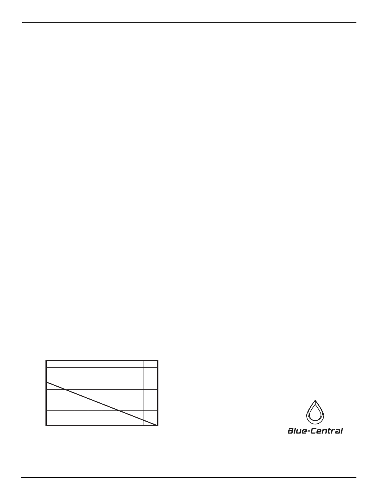
INLINE PIPE FITTING TEMPERATURE VS PRESSURE
0 25 50 75 100 125
70° F (21° C)
110° F (43° C)
150° F (65° C)
150
80° F (27° C)
90° F (32° C)
100° F (38° C)
120° F (49° C)
130° F (54° C)
140° F (60° C)
160° F (71° C)
175 200
WORKING PRESSURE (PSI/g)
Temperature Vs. Pressure Chart:
1.0 Introduction
®


