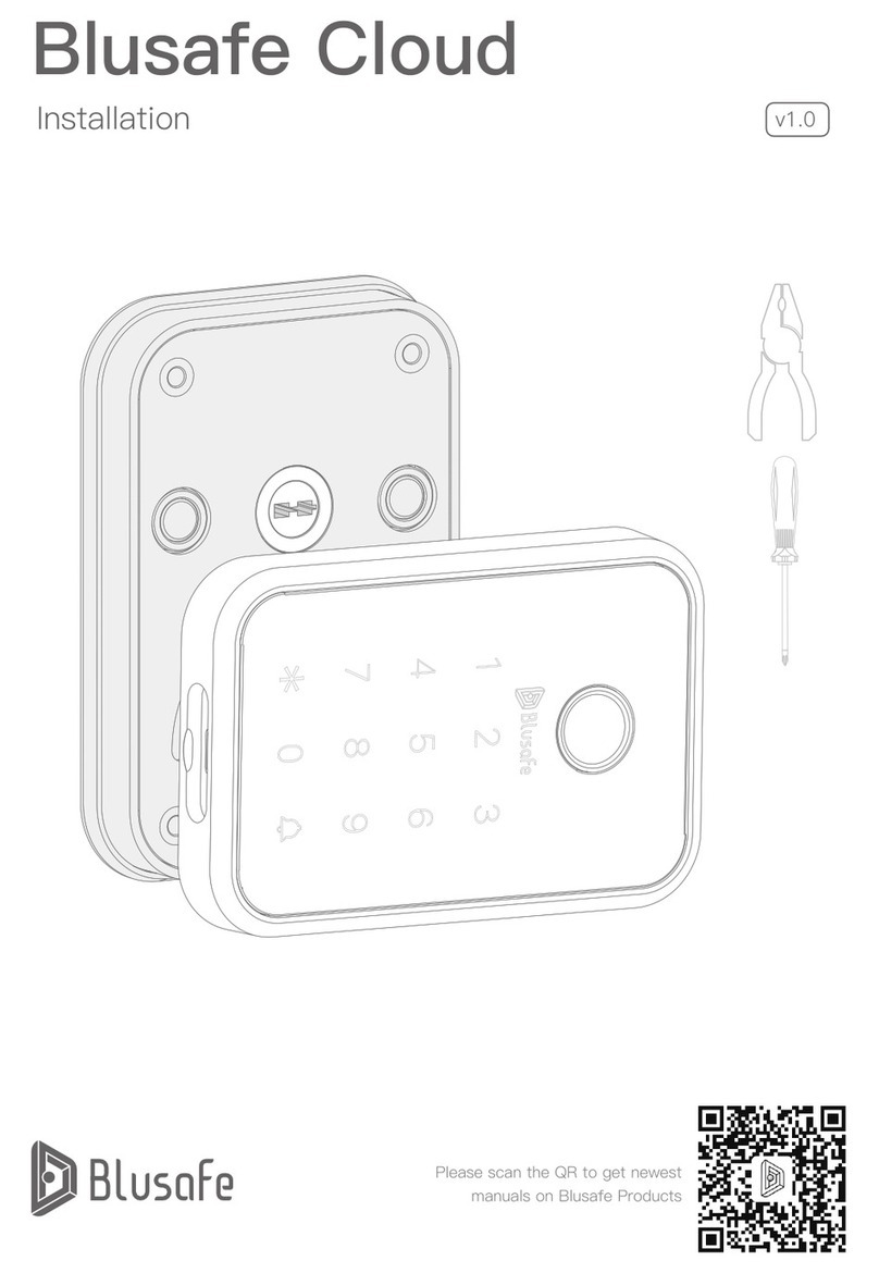
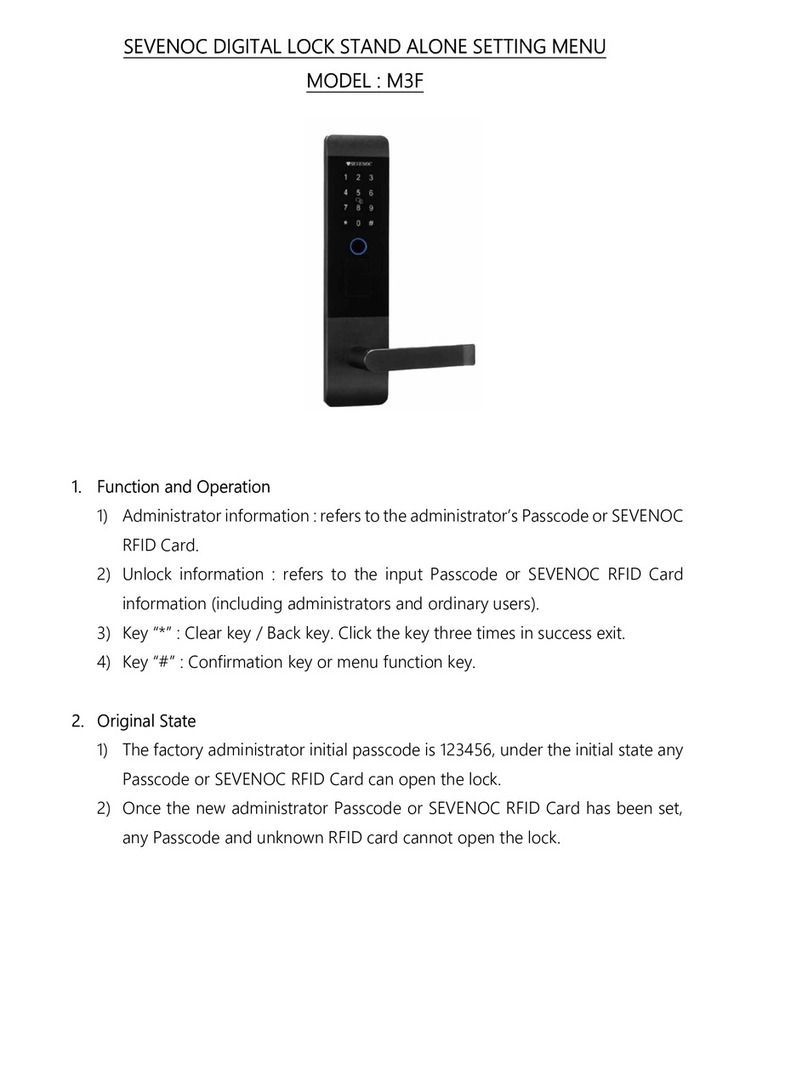
Blusafe Contour User manual

1P
Blusafe Contour / Contour V
Installation Manual
Please scan the QR to get newest
manuals on Blusafe Products
v1.1

2
P
0. Tools Required
1. Package Contents
2. Latch Installation Guide
3. Blusafe Contour Smart Lock
4. Determine Handle Direction
5. Change External Handle Direction
6. Change Internal Handle Direction
7. Installation of Blusafe Contour Smart Lock
P0
P1
P2
P4
P5
P6
P7
P8
Installation Manual Contents
Tools Required
Pliers
Pencil
Hammer
Drill Bits
Chisel
Drill
Tape Measure
Screwdriver

1P
Internal Panel
Strike Plate
A - ST 3.9 x 20mm Self
Tapping Screw x 4
C - Screw Pillar
x 1
F- Key
x 3
Mounting plate
Strike Box
B1- M4 x 35mm
Screw x 4
D - ST 3.9 x 16mm Self
Tapping Screw x 1
G - Keycard
x 2
External Panel
Latch
B2- M4 x 50mm
Screw x 4
E- Screwdriver
x 1
H- M4 x 10mm
Screw x 4
Package Contents
1. Package Contents P1

2
P
35mm to 54mm
1-2/5” to 2-1/8”
1"
26mm
2-5/16"
58mm
1"
Φ25mm
2-3/8"or 2-3/4"
60 or 70 mm
121mm
4-3/4"
2/5"
Φ10mm
2-1/8"
Φ54mm
It is suggested to drill both holes on door in
order to have best installation of the lock
afterwards.
If you choose not to drill the 2/5" (Φ10mm)
hole, the C Screw Pillar will not be used in the
"Installation of Contour Smart Lock".
Note
①TheContourhandleissuitabletouse
ondoorthicknessbetween1-2/5"and
2-1/8"(35and54mm).
Thebelowlatchinstallationguideismeantfornewdoorsthatdonotalreadyhave
holesforthelockorlatch.Ifyourdooralreadyhastherequiredholestoinstallthe
latchandlock,youmayskipthebelowstepsandproceedtoP04.
②Usethetemplateguidetomarktheholes
ondooratrequiredheights(suggested
heightforΦ54mmholecentrelineis
38"or970mmfromthebaseofdoor).
Drillouta2-1/8"(Φ54mm)anda2/5"
(Φ10mm)hole.
③Foldthetemplateguidealongtheedge
ofthedoorandpositionitoverthe
2⅛"(54mm)diameterhole.Markthe
1"(25mm)diameterholeontheedge
ofthedoorforthelatch.Drilloutthe1"
(25mm)diameterlatchhole.Chiselout
theremainderoftheslotontheedgeof
thedoortoacceptthelatchbody.This
isarectangle1"x2¼"(26mmx58mm)
asshownabove.Thedepthshouldbe
⅛"(3mm)toacceptthelatchbody.
Pleasetesttthelatchbodytoensurea
goodtbeforeinstalling.
Drill Lockset and Latch Holes
10.6070.5525
Latch Installation Guide
2. Latch Installation Guide P2 - P3

3P
15/16"(24mm)
1-1/8"(29mm)
1-1/8"(29mm)
2-3/4"(71mm)
1-3/8"(36mm)
Strike Plate
Strike Box
2-3/8" (60mm)
2-3/4" (70mm)
35mm to 54mm
1-2/5” to 2-1/8”
1"
26mm
2-5/16"
58mm
1"
Φ25mm
2-3/8"or 2-3/4"
60 or 70 mm
121mm
4-3/4"
2/5"
Φ10mm
2-1/8"
Φ54mm
Adjustthelatchlengthaccordingtobackset(2-3/8"(60mm)or2-3/4"(70mm)).
Fixtwoselftappingscrewsontothelatchplate.
①Withthelatchinstalled,extend
thelatchoutandgentlyclose
againstthedoorframe.Markon
theframethetopandbottomof
thelatch.
②Markacentrelinedownthejamb
forthestrikeplate.Ensurethis
centrelineallowsdoorenough
spacetocloseagainstthestop.
③Placethestrikeplateonthe
jambaligningthemarksfrom
thelatchtotheholeforthebolt.
Alsoensurethestrikeplateis
centredonthecentrelinemarked.
Scribearoundtheouteredgeof
thestrikeplatewithapenciland
chiselwithinthescribedareatoa
depthof1/12"(2mm).
④Fitthestrikeplateintorecessed
holeandmarktheholeforlatch.
⑤Chiseltheholeouttoadepth
of1"(25mm)toallowthelatch
extendandmovefreely.
⑥Insertthestrikeboxandstrike
plateintothehole.Screwinthe
strikeplateasshown.
Latch Installation Guide
Install the Latch
Install Strike Plate and Box
2. Latch Installation Guide P2 - P3
Screwdriver A × 2
A × 2

4
P
Blusafe Contour Smart Lock
3. Blusafe Contour Smart Lock P4
Battery Cover
Internal Handle
Louderspeaker Hole
Internal Panel
External Panel
Camera
(Only available in
Contour V)
Micro USB
Cylinder Cover
Key Card Area
Keypad
Fingerprint
Sensor
Mechanical
Key hole
External
Handle

5P
Determine Handle Direction
Dependingonwhichwayyourdooropens,determinewhichwaythehandlesneed
toface.
Thehandlesshouldalwayspointtowardsthedoorhinges.ChecktheContour/
ContourVhandlesagainstthecurrenthandles.
Ifthehandlesneedtofacetheotherway,pleaseseenextpage.
4. Determine Handle Direction P5

6
P
4. Rotate the spindle
downwards by 45 degrees
until seeing the screw
hole. Locate and fasten
the set screw.
3. Rotate the
handle downwards
from its horizontal
position, by 225
degrees.
1.Rotate the handle
and the spindle by 45
degrees to expose the
set screw.
2. Unwind the set screw.
screw hole
Change External Handle Direction
Screwdriver
5. Change External Handle Direction P6

7P
2.Rotate the handle
downwards by 180
degrees.
1.Unwind the set screw.
3. Locate and fasten
the set screw.
4. Rotate the spindle
downwards by 45 degrees
until seeing the screw
hole. Locate and fasten
the set screw.
3. Rotate the
handle downwards
from its horizontal
position, by 225
degrees.
1.Rotate the handle
and the spindle by 45
degrees to expose the
set screw.
2. Unwind the set screw.
screw hole
Change Internal Handle Direction
Screwdriver
6. Change Internal Handle Direction P7

8
P
Pleasemakesurethelatchisinstalledproperlyasperthe"LatchInstallationGuide"
priortothefollowinginstallationsteps:
①Measurethedoorthickness.
②Pleaseselecttheappropriatescrewsbasedonthedoorthickness.Youcanrefer
totheabovetableforreference.
Installation of Blusafe Contour Smart Lock
Select the xing screw
of appropriate length
according to the door
thickness.
Boor Thickness/mm Screw B Length
1 - ²/₅" t o 1 - ⁴/₅ " (35-45mm) M4×35mm
M4×50mm1 - ⁴/₅ " t o 2 - ¹/₈ " (45-54mm)
Tape Measure
7. Installation of Blusafe Contour Smart Lock P8 - P16

9P
③TightentheCScrewPillarontothebackoftheexternalpanel.
④Pullthecableoftheexternalpanelthroughthebottomofthehole.Insertthe
spindlethroughthespindleholeofthelatch.Pushtheexternalpanelcarefully
intothedoor,andmakesuretheCScrewPillarfeedthroughtheupperholeof
thedoor.
Please use the 3M tape at the back of external panel to reinforce the mounting.
Tip
Installation of Blusafe Contour Smart Lock
Please peel o the skin and
use the 3M tape at the back
of external panel to reinforce
the mounting.
The C Screw Pillar must
be used if the smart lock is
exposed to rain, to ensure the
best installation and weather
seal.
Make sure the cable
is pulled through the
bottom of hole.
Tip
Warning!
Pliers C × 1
7. Installation of Blusafe Contour Smart Lock P8 - P16

10
P
⑤Pullthecablethroughtheslotofthemountingplate.
Installation of Blusafe Contour Smart Lock
Make sure the cable
is pulled through the
bottom of hole.
7. Installation of Blusafe Contour Smart Lock P8 - P16

11P
⑥DrivethescrewsinbutdoNOTtightenthemalltheway.Adjusttheexternal
paneltothecorrectpositionandthenproceedtotightenthescrews.
Installation of Blusafe Contour Smart Lock
B × 3 D × 1
B × 1
or
+
Alternative
If you used the 3M glue only
and not the C Screw Pillar on
external panel, please use the
ST3.9x16mm self-tapping
screw D instead of the B Screw
at the top.
B Screw × 3
B Screw or
D Screw
7. Installation of Blusafe Contour Smart Lock P8 - P16
Screwdriver

12
P
Installation of Blusafe Contour Smart Lock
⑦Unwindthebatterycover
screwwithEScrewdriver
provided,takeothe
batterycover.
E × 1
7. Installation of Blusafe Contour Smart Lock P8 - P16

13P
Installation of Blusafe Contour Smart Lock
The cable MUST be
pulled through this slot.
⑧Connecttheexternalandinternalcablestogether.
7. Installation of Blusafe Contour Smart Lock P8 - P16
Please make sure the cables are connected in the correct orientation otherwise will cause
permanent damage to the lock!
Warning!
Red
White
Red
Red

14
P
Installation of Blusafe Contour Smart Lock
⑨Buckletheinternalplateontothemountingplate.FixtheHScrewswitha
screwdriver.
H × 4Screwdriver
7. Installation of Blusafe Contour Smart Lock P8 - P16

15P
Installation of Blusafe Contour Smart Lock
⑩Rotatethehandletoensurethelatchcanbeextendedandretractedfreely.Stand
inside,closethedoorandrepeattherotationofhandle.Ensurethelatchcanstill
beextendedandretractedfreely.Ifnot,youmayneedtoadjustthepositioning
ofthelatchinthedoor.
⑪Openthebatterycassette.Insert8AAbatteriesasshownabove.
Ensure the batteries
are inserted correctly.
For the best experience possible, please use high quality AA batteries in your Smart Lock.
The batteries will last for 6-8 months depending on usage and environment; however,
recommend you change the batteries every six months or when notied to do so in your
App.
Note
7. Installation of Blusafe Contour Smart Lock P8 - P16

16
P
Installation of Blusafe Contour Smart Lock
⑫Putonthebatterycover,xthescrewwiththeEScrewdriver.
E × 1
7. Installation of Blusafe Contour Smart Lock P8 - P16

17P
Securityatyourngertips——Blusafe

18
P
Please scan the QR to get newest
manuals on Blusafe Products
Other manuals for Contour
1
This manual suits for next models
1
Table of contents
Other Blusafe Door Lock manuals
Popular Door Lock manuals by other brands
Allegion
Allegion Schlage L-Series Service manual
Emtek
Emtek Keypad Deadbolt Locksets Installation & programming guide
Fortress Technologies
Fortress Technologies DM4-CLIN installation instructions

Kit-Lock
Kit-Lock KL1000 Programming & operating instructions

ZKTeco
ZKTeco GL300 user manual
VON MORRIS
VON MORRIS 9001 installation instructions
