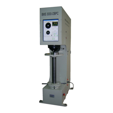
Bms Bulut Makina 3000-OBPC User manual

2
1TECHNICAL SPECIFICATIONS___________________________________________________________3
1.1 TECHNICAL SPECIFICATIONS _____________________________________________________________ 3
FEATURES OF OPTOBUL SOFTWARE _____________________________________________________________ 3
1.3 STANDART ACCESSORIES:___________________________________________________________________ 3
2.ABOUT MACHINE _____________________________________________________________________4
2.1 PART LIST________________________________________________________________________________ 4
2.2 PICTURES OF EQUIPMENT __________________________________________________________________ 5
3.GENERAL INFORMATION _______________________________________________________________7
3.1 BRINELL HARDNESS TESTING (EN 6506-1, ASTM E10) _____________________________________________ 7
3.2 PRIOR TO TESTING ________________________________________________________________________ 7
3.3 CHOOSING THE TESTING METHOD & OBSERVING SURFACE________________________________________ 7
1.1 TESTING _____________________________________________________________________________ 7
4.DIRECTIONS __________________________________________________________________________8
1.1 ADDRESS____________________________________________________________________________ 12
1.1 CUSTOMER __________________________________________________________________________13
4.3 HARDNESS TEST: _________________________________________________________________________ 14
4.4 REPORTS _____________________________________________________________________________ 21
5.CARE INSTRUCTIONS __________________________________________________________________22
6.WARRANTY CONDITIONS ______________________________________________________________22
IMPORTANT
Please read this manual carefully before commissioning and running the equipment
In manual, there are several warning notices which to be paid attention.
And their meanings to be explained accordingly..
In case of facing problems, please get in touch with us. We will be pleased to solve your problems.
A–Your company name, address, phone fax number, type of equipment, serial number
B–Problem to be explained clearly
Above notices will be helpful to assist you.

3
1 TECHNICAL SPECIFICATIONS
1.1 TECHNICAL SPECIFICATIONS
Load cell (closed loop) system
Test Loads (kgf) : 62, 5-3000
Load Selection : Automatic
Test Method : Brinell
Load Application : Automatic
Measuring system : Digital camera
Depth of Throat : 200 mm
Max. Test height : 430 mm
Power supply : 220V, 50Hz
Machine Dimensions : 1500 x 810 x 485 mm
Case Dimensions : 1800 x 1000 x 700 mm
Weight (net/gross) : 400 / 500 kg
Closed-loop system
Video Imaging
Windows based
15” Full Color Touch screen
1.2 FEATURES OF OPTOBUL SOFTWARE
Test methods, name of customer and user, part no (automatic when required), part name, upper and
lower tolerances, mean value, clearing records according to month and part number, conversions, very
sensitive testing using up-down keys on screen when required, RS 232 output, printing reports (ball
indentation view can also be printed out), graphic, standard deviation, user calibration, factory settings,
internet connection, user friendly
1.3 STANDART ACCESSORIES:
5 and 10 mm ball indenters : 1
HB 5 / 750 and 10 / 3000 test blocks : 1
Flat Testing Table : 1
V Testing Table : 1
Hardness Conversion Table : 1
Case for Accessories : 1
Set of alien spanners : 1
Instruction Manual : 1
Calibration Certificate : 1

4
2.ABOUT MACHINE
2.1 PART LIST
1. Body
2. Motoring Systems On / Off
3. Mains Cable
4. Light Adjustment Button
5. Touch Screen Panel
6. Clamping Attachment
7. Ball İndenter
8. Testing Table
9. Test Sample
10. Elevating Screw
11. Arm
12. Elevating Screw Nut
13. Volt, 10 Watt Halogen Lamp
14. Step Motor Spindle
15. Driver For Step Motor
16. Power Supply For Driver Of Step Motor
17. Load Cell İndicator
18. Light On/Off
19. Computer System ON/OFF
20. Emergency Button
21. PC System

5
2.2 PICTURES OF EQUIPMENT
PICTURE-1
Touch screen
panel (5)
Ball indenter (7)
Test Sample (9)
Arm (12)
Elevating screw nut (11)
Elevating screw (10)
Clamping attachment 6)
Clamping attachment (6)
Elevating screw nut (12)
Arm (11)
Light ON/OFF(18)
Touch screen panel (5)
Elevating screw (10)
Testing Table(8)
Body (1)
Emergency button(21)
Motoring systems ON/OFF(2)
Mains Cable (3)
Computer systems ON/OFF (20)
Light adjustment (4)
Test Sample (9)

6
PICTURE-3
PICTURE-4
Testing table (8)
12 Volt,10 Walt halogen lamp (13)
Clamping attachment (6)
Ball indenter (7)
Step motor spindle (14)
Load cell indicator(17)
Driver for step motor(15)
Power supply (55V)for
driver of step motor(16)
Orijinal Windows Label
PC system(21)
PICTURE A

7
2 GENERAL INFORMATION
2.1 BRINELL HARDNESS TESTING (EN 6506-1, ASTM E10)
Brinell hardness testing method is actuated by balls with several sizes depending on material type,
thickness and loads applied. Diameters of ball indentations can be evaluated by optical system built-in
hardness tester.
Relations with thickness of specimen, ball dia and material shown in related the table
Thickness of
material (mm)
Ball dia(mm)
P=30D2
Steel, iron,
cast iron
P=10D2
Brass, Bronze,
Cupper,
Aluminyum
P=D2
Soft cupper
P=5D2 Lead
6 mm and up
10
3.000 kgf
1.000 kgf
500 kgf
250 kgf
3 mm and up
5
750 kgf
250 kgf
125 kgf
62,5 kgf
1,2 mm and up
2,5
187,5 kgf
62,5 kgf
31,25 kgf
15,625 kgf
Table 1
2.2 PRIOR TO TESTING
First switch on computer systems ( 22 in Picture 1) ,after then, switch on touch screen panel
(1 in Picture 5) .Later, switch on, motoring system (1- Picture 2).
Run OPTOBUL Software on touch screen panel. Equipment optical positioned automatically.
Locate suitable ball indenter into indenter holder using Table 1
2.3 CHOOSING THE TESTING METHOD & OBSERVING SURFACE
Choose Brinell hardness testing method in settings (ball/load)
See OPTOBUL software
Locate, sample on testing table.
Raise, elevating screw until clamping attachment touches on the surface of sample.
At this time, observe, surface of sample on touch screen panel.
2.4 TESTING
Press to the START
Swiveling starts from the optical position to loading position & test loading begins.
When load application, dwelling starts and when it is over, device automatically swiveled to the optical
position.
In the meantime, ball indentation shown in the screen.
Pls follow OPTOBUL program.
Measurement to be made clean and smooth surfaces must be measured in terms of health.

8
3 DIRECTIONS
Hardness Tester software OPTOBUL3
Once installed, the program is first opened Activation Code input window appears.
After entering this code "Continue" button.

9
Login window, the first user to setup the following window: BMS, Password: Enter BMS. (In later entries,
pre-defined user name and password to enter).

10
Main Window the following menu headings Optobul3 are common;
1-Address information
2-Customer Information
3-Hardness Test procedures,
4-Logged; program user,
5-User management,
6-Database Backup and Restore
7-Language Selection,
8-Program update,
9-Program exit
The first step, go to Main Window from the user and the program will use the item of the menu descriptions
of people do. Name and Surname details will be written here, test reports "test," information will be used as.
To define a new user, press new button once, then Login, Password, Name and Last Name
boxes to fill. User rights determine and record button.

11
To change a user's information registered in the list below select the name you want and make
changes and save them press.

12
3.1 ADDRESS
From the main menu by pressing the Address button, enter your company address information. First,
press the New button, fill in the blank field and press the Save button.

13
3.2 CUSTOMER
From the main menu by pressing customer, enter the customer address information. First, press the
New button, Fill in the blank field and press the Save button.

14
3.3 HARDNESS TEST
From the main menu, press the test and measurement from the screen you make the transition to the
screen the following window fill in the fields and "forward" button.
System, load calibration and calibration as will be made with the display settings. Do not need them
to do initial setup.
Test Method selection ball-diameter, Load, objective, lower limit and upper limit, check their values.

15
Measurement and Test tab, you can make measurement by pressing Test button. After pressing Test button
please wait until the machine completes it process and shows you the figure below.

16
Measurement process starts by creating traces
on the material
Monitoring the process of creating a starting
position and the device returns to its stops.
Press Start button to start measurement

17
After you create something like the following figure in the window to create the image. From left to
right and from top down approach from the buttons to perform the measurement.

18
To make precise measurements must be measured normal once, then tab precise measurement
precision approach allows you to make more accurate your measurements you can use the button.
From up
From left
From down
From right
Conversion
table
Device
makes
the staring
position
Cycle of
The
measuement
result

19

20
precise measurement of the left precise measurement from the right
above approach
below approach
Other manuals for 3000-OBPC
1
Table of contents
Other Bms Bulut Makina Test Equipment manuals
Bms Bulut Makina
Bms Bulut Makina Hartip-3210 User manual

Bms Bulut Makina
Bms Bulut Makina JB-300S Quick start guide

Bms Bulut Makina
Bms Bulut Makina HTP 1600 User manual

Bms Bulut Makina
Bms Bulut Makina HARTIP 3000+ User manual

Bms Bulut Makina
Bms Bulut Makina 3000-OBPC Quick start guide

Bms Bulut Makina
Bms Bulut Makina BMS 200-RBOV Quick start guide
Bms Bulut Makina
Bms Bulut Makina HARTIP-4100 Quick start guide

Bms Bulut Makina
Bms Bulut Makina DIGIROCK-RB Quick start guide
Bms Bulut Makina
Bms Bulut Makina BMS 3000-OBLC Quick start guide
Bms Bulut Makina
Bms Bulut Makina SR210 User manual