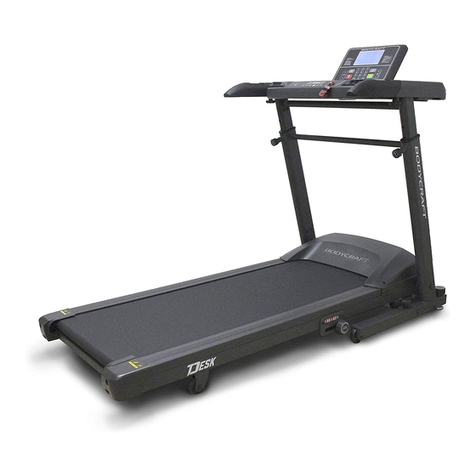
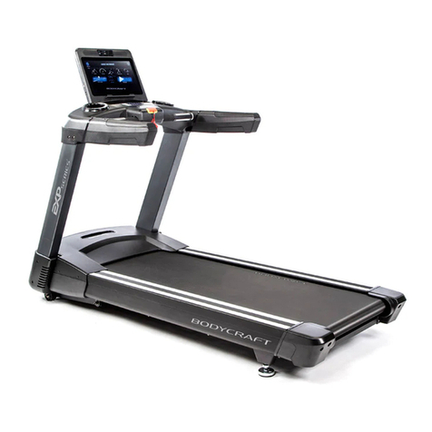
Body Craft EXP Series User manual

Base Serial Number: T402_ _ _ _ _ _ _ _ _ _ _ _
Console Serial Number: _ _ _ _ _ _ _ _ _ _ _ _ _
Purchased Date: ___ / ___ / ______
Dealer’s Name:__________________________
Please register your products at:
https://www.bodycraft.com/product-registration/
Open your Camera App
and point it at the QR
Code for additional
information.
http://www.bodycraft.com/
U1000-U1K1-qr.html
Owner’s Manual
T402 v1.6
1
To see this manual in
FULL COLOR
scan this QR code.
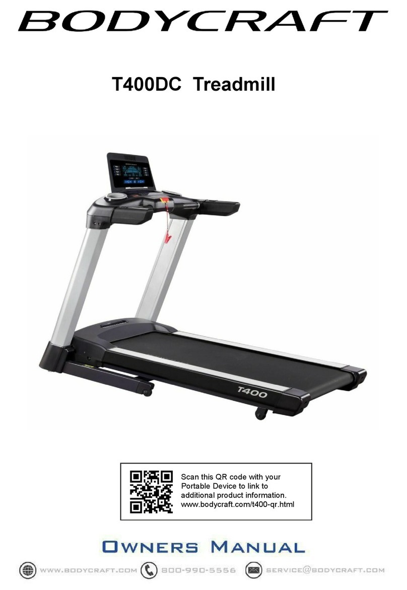
T400 Treadmill
Open your Camera
App and point it at
the QR Code
Serial Number
Serial Number
To see in
FULL COLOR
& additional information,
scan this QR code.

This page intentionally left blank

Congratulations and Welcome to the BODYCRAFT Family
Thank you for selecting BODYCRAFT. Your choice reflects a wise investment in you and your
facility. We hope you use it for many healthy years!
BODYCRAFT offers a complete array of high-quality fitness equipment. Please refer to our website at
www.bodycraft.com to view more ways to enhance your lifestyle.
Your BODYCRAFT machine has all the quality and design elements to make your workout extremely efficient
and comfortable. Your new unit is a serious cardio machine that will keep you motivated, challenged and
within reach of your fitness goals. Strength & cardiovascular training is vital for all ages which will provide an
effective workout, producing results that will encourage you to reach your fitness goals and maintain the
body you have always wanted.
Spending 15 to 30 minutes a day, three times a week, is all you need to start seeing the benefits of
a regular exercise program.
As a premium exercise equipment manufacturer, we are committed to your complete satisfaction. If you
have questions, suggestions or find missing or damaged parts, we guarantee your complete satisfaction
through our authorized dealer network or by contacting us directly. Please call your local dealer or
BODYCRAFT.
BODYCRAFT (a division of Recreation Supply, Inc.)
7699 Green Meadows Dr.
Lewis Center, OH 43035
Phone: 800-990-5556 9 am - 5 pm EST Email: service@bodycraft.com
Proof of purchase must be supplied to validate warranty and the product must have been
registered with BODYCRAFT via online at www.bodycraft.com or by calling 800-990-5556
or 740-965-2442 M-F 9 a.m. - 5 p.m. EST.
For parts orders, owner’s manuals, software
update files, exercise guides and contact
information scan this QR code.
Or go to:
https://www.bodycraft.com/customer-support

Product Safety Information
FCC Information …………………………………………………………………...
Product Safety ……………………………………………………………………..
Power & Grounding Requirements
Grounding Instructions …...................................................….………………..
Power Requirements ……………………………... .……………………………..
Product Overview
Product Overview Components & Tools for Assembly .………………………..
Product Specifications …………………………………………………………….
Shipping Boxes and Pre-Assembly TIP ……………………………………….
Assembly Parts & Hardware ..…………………………………………………….
How Assemble the Treadmill
Product Assembly Instructions ..........................................…………………...
How to Setup the Treadmill
Folding & Moving the Treadmill ………………………………………………….
Unfolding the Treadmill ………………………………………………………….
Wall Outlet, Breaker and Extension Cords .........................………….………...
Spacing Requirements …...................................................………….…………
Leveling the Treadmill (Making it stable) ………………………………………..
Running Belt Tension & Alignment ……………………………………………….
Installation Checklist ………………………………..…………………………….
Operation Instructions
Console Options……………….………………………………………………….
Console Operating Instruction ………………………………………………….
Safety Key Clip & Tether ………………………………………………………..
Heart Rate Monitoring Grips & Wireless Receiver ……………………..........
Erratic Heart Rate Readings & Exercise Tips ………………………………...
4
Table of Contents
Page
5
6 - 7
8
8
9
10
11
12
13- 24
25
26
24
27
27
28
29
30
31
31
32
33
Energy Saving function: These treadmill consoles are equipped with a power saving
function. This means after 10 minutes of inactivity, the treadmill will automatically power off.
Press any key on the dashboard to wake up the console from power save mode.

Caution: Please note that changes or modifications not expressly approved by the party responsible for
compliance could void the user's authority to operate the equipment.
This device complies with Part 15 of the FCC Rules. Operation is subject to the following two conditions:
(1) This device may not cause harmful interference, and (2) this device must accept any interference
received, including interference that may cause undesired operation.
NOTE: This equipment has been tested and found to comply with the limits for a Class B digital device,
pursuant to Part 15 of the FCC Rules. These limits are designed to provide reasonable protection against
harmful interference in a residential installation. This equipment generates, uses and can radiate radio
frequency energy and, if not installed and used in accordance with the instructions, may cause harmful
interference to radio communications. However, there is no guarantee that interference will not occur in a
particular installation. If this equipment does cause harmful interference to radio or television reception,
which can be determined by turning the equipment off and on, the user is encouraged to try to correct the
interference by one or more of the following measures:
Reorient or relocate the receiving antenna.
Increase the separation between the equipment and receiver.
Connect the equipment into an outlet on a circuit different from that to which the receiver is connected.
Consult the dealer or an experienced radio/TV technician for help.
FCC CAUTION: Changes or modifications not expressly approved by the party
responsible for compliance could void the user’s authority to operate this equipment.
Table of Contents
FCC Information
Page
Maintenance & Repairs
Cleaning your Treadmill….........................................................…………….
Preventive Maintenance ….........................................................…………….
Lubricating the Running Belt / Deck Area & Lube Icon ..….……...…………
Required Info BEFORE Initiating a Service Case …………………………..
Troubleshooting & Error Codes ………………………………………………...
Circuit Diagram .............................................................................................
Parts Lists ………..………….………………………………………….………..
Parts Exploded Views .………………………………….…………….………….
Warranty
Product Warranty ..............................................................….……..….……..
Product Warranty Registration ................................................….…..……...
Contact Us Information …………………………………………………………..
34
35
36
37
38 - 39
40
41 - 43
43 - 47
48
49
50
5

Safety and Warnings - T400 (T401 & T402) 1 of 2
6
There is a risk assumed by individuals who use this type of equipment.
A moment’s lack of attention can result in an accident, as can failure to
observe certain simple safety precautions.
Read, study and understand the Assembly Instructions and all the warning labels on this
product. Furthermore, it is recommended to familiarize yourself and others with the proper
operation and workout recommendations for this BODYCRAFT product prior to use.
● Keep children under the age of 13 and pets away from the equipment at all times. Do not
allow children and pets to use or play on the equipment. Keep children and pets away
when it is in use.
● The treadmill is not intended for use by persons with reduced physical, sensory, or mental
capabilities or lack of experience and knowledge, unless they have been given supervision
or instruction concerning use of the treadmill by someone responsible for their safety.
● Wear the safety cord and clip all times while using the treadmill. Always stand on the side
rails before the treadmill starts.
● Before beginning any exercise program on the treadmill, it is important to consult with your
physician if you have any of the following: history of heart disease, high blood pressure,
diabetes, chronic respiratory diseases, elevated cholesterol, if you smoke cigarettes or if
you experience any other chronic diseases or physical complaints.
● If over the age of 35 or overweight or pregnant, consult with your physician before
beginning any exercise program.
● If you experience dizziness, nausea, chest pains or other abnormal symptoms during
exercise, stop the exercise session immediately. Consult your physician before continuing.
● Drink fluids if you exercise for twenty or more minutes on the treadmill.
● Always follow the console instructions for proper operation.
● Never operate your treadmill if it has a damaged cord or plug, or if it is not working
properly. Contact your authorized BODYCRAFT fitness dealer for service and repair.
● Keep the power cord away from heated surfaces.
● Never insert any objects or body parts into openings.
● Keep hands and feet away from all moving parts.
● Use the handrails when getting on and off your treadmill.
● Check the power requirement for your unit to see if it matches your local power outlet.
● Do not operate the heart rate monitor transmitter together with an electrical heart
pacemaker. The transmitter may cause electrical disturbances.
● Inspect this treadmill prior to exercising to ensure it is working properly. Always make sure
all components are fastened securely.
● This treadmill is intended for indoor use. Do not place the unit outdoors or any damp or wet
locations.
Safety and Warnings - T400 (T401 & T402) 2 of 2
● Keep the treadmill away from walls to allow proper ventilation. Air should be able to circulate
freely around the unit. Keep all air openings free of dirt and dust.
● Place the treadmill in an area that will meet minimum clearance requirements: Front 12” (.3m),
Sides: 20” (.5m) & Back 79” (2m) and from any obstruction object while using the machine.
● Wear proper exercise clothing and shoes for your workout and avoid loose clothing. Never
exercise in bare feet or socks; always wear correct footwear, such as running, walking, or
cross-training shoes.
● Higher speed and higher incline is not for everyone. It is designed for occasional use of a skilled
runner and may exceed many users’ capabilities. Stop right away if you feel any discomfort. Never
walk or jog or run backwards on the treadmill.
● Place your treadmill on a solid, level surface when it is in use. Adjust the levelers at the rear of
the treadmill if necessary.
● Be careful to maintain your balance while using, mounting, dismounting, or assembling the
equipment. Loss of balance may result in a fall and serious bodily injury. Use care when getting
on or off the treadmill. When stepping on the running belt, always grasp the handrail and keep the
initial speed at or below 1 mile per hour (mph).
● Make sure the running belt is at a complete stop before exiting the machine.
● Never leave the treadmill unattended when plugged in. Unplug from outlet when not in use, before
putting on or taking off parts. When the treadmill is not in use, disconnect the treadmill by turning
the power switch to the Off position, and then remove the power plug from the electrical outlet.
● Always attach the Safety key securely to your clothing when using the treadmill.
● Do not pull the treadmill by the power cord or use cord as a handle. Always use two hands to lift
the treadmill and roll it on its front wheels.
● Keep the power cord away from heated surfaces.
● Keep the top side of the moving surface clean and dry or potential injury will occur.
● Read, understand, and test the emergency stop procedures before use.
● To ensure proper function of your treadmill, do not install attachments or accessories not
provided or recommended by BODYCRAFT.
● This T400 Treadmill is intended for home use only. DO NOT use the treadmill in any commercial,
rental, or institutional setting. Use only for its intended purpose described in this manual.
● The T400 Treadmill user’s weight is not to exceed 350 lbs (159 kgs).
7

Safety and Warning for a Treadmill - Power Requirements T400 (T401 & T402)
Safety and Warning for a Treadmill - Grounding Instructions
8
DANGER - Improper connection of the equipment-grounding conductor can result in a risk of electric
shock. Check with a qualified electrician or serviceman if you are in doubt as to whether the product is
properly grounded. Do not modify the plug provided with the product if it will not fit the outlet; have a
proper outlet installed by a qualified electrician.
This product is for use on a nominal 120 volt wall circuit, and has a grounding plug that looks like the
plug illustrated in the figure. Make sure that the product is connected to an outlet having the same
configuration as the plug. No adapter should be used with this product.
This product must be grounded. If the
treadmill’s electrical system should
malfunction or breakdown, grounding
provides a path of least resistance for electric
current, reducing the risk of electric shock.
This product is equipped with a cord having an
equipment-grounding plug. The plug must be
plugged into an appropriate outlet that is
properly installed and grounded in accordance
with all local codes and ordinances.
A power strip should never be used. Extension cords should be avoided, but we
realize that in some cases an extension cord is needed. In this case, Appliance
Grade extension cords are available at most hardware stores. Buy only the
minimum length required; avoid anything longer than 6 feet. Try to find one made
with 12 gauge wire (3-wire is required). Do not use an adapter with your treadmill.
To reduce the risk of electric shock,
always unplug the treadmill from the electrical
outlet before cleaning or lightning storms.
It is recommended that your treadmill be plugged into a Dedicated 120V/15A
for home use. The treadmill must be connected to a grounded receptacle
having the same configuration as the plug. Do not modify the plug provided
with this product. If it will not fit the outlet, have a proper outlet installed by a
qualified electrician.
NOTE: DO NOT USE an GFCI wall outlet. A
treadmill uses the ground on the outlet to
disperse static electricity generated by it’s belt,
deck and motor design. Highly likely if using an
GFCI outlet, it will trip the breaker and shut down
the treadmill, potentially causing the treadmill’s
electronics failure or serious injury to the user.

THE FOLLOWING TOOLS ARE RECOMMENDED FOR EASIER ASSEMBLY:
SOCKET SET WITH 3“ & 6”
EXTENSION for 13mm & 17mm
OPEN & CLOSED WRENCHES
for 13mm & 17mm
ALLEN WRENCHES SET
4mm to 10mm)
PHILLIPS SCREWDRIVERS
#2 w/ Magnetic TIP
TORQUE WRENCH 3/8 DRIVE
TIP ON FRAME ONLY: For extra
protection from fingerprints,
sweat stains or just plain dirt,
apply an automotive grade
cleaner wax if desired. Also
makes future cleaning easier.
THE FOLLOWING IS RECOMMENDED FOR CLEANING:
100% COTTON
CLEANING CLOTHS (Do Not Use on the Upholstery)
MILD CLEANING
SOLUTION
Product Overview Components and Tools for Assembly - T800 (T802)
Product Overview Components and Tools for Assembly - T400 (T402)
ALLEN WRENCHES SET
(4mm to 10mm)
PHILLIPS SCREWDRIVER #2
w/ Magnetic TIP
9
THE FOLLOWING TOOLS ARE
INCLUDED FOR ASSEMBLY:
TORQUE WRENCH 3/8 DRIVE
w/ 5mm & 6mm ALLENS
TORQUE WRENCH 3/8 DRIVE
w/ 5mm & 6mm ALLENS
THE FOLLOWING TOOLS ARE RECOMMENDED FOR EASIER ASSEMBLY:

10
Product Specifications - T400 (T402)
RUNNING BELT: 20” W x 61” L x 2.0mm T
RUNNING DECK: 1” Thick Reversible Deck
HANDRAILS: 10.25” Custom Molded Soft Touch
DIMENSIONS: 80” L x 35” W x 59” H
WEIGHT: 260 lbs (Assembled)
MAX USER WEIGHT: 350 lbs
Physical
Dimensions
Shipped
Dimension
Shipped
Dimension
Box 1 Box 2
Length 80.3"/204cm 90.5"/230cm N/A
Width 35.6"/90.5cm 38"/97.5cm N/A
Height 59.3"/150.6cm 13.7"/35cm N/A
Weight w/
console
254lb/115kg 282lb/127.7kg N/A
PRODUCT SPECIFICATIONS

BODYCRAFT reserves the right to make improvements at any time which may affect
color, parts, materials, size, weight, or any other aspect.
Shipping Boxes and Pre-Assembly Tip - T400 (T401 & T402)
Small Box 2 of 2
1 each @ 9 lbs
(T9LCD/T10TS)
or
1 each @ 10 lbs (T16TS)
19” x 6.25” x 5”
Pre-Assembly TIP: Place all parts from the boxes in a cleared area and position them on the floor in
front of you. Remove all packing materials from your area and place them back into the box. Do not
dispose of the packing materials until assembly is completed.
Read each step carefully before beginning.
(Includes the console model that was ordered)
Large Box 1 of 2
1 each @ 289 lbs
91” L x 39” W x 14” H
Width & Top View
Full Length (Side) View
11

Assembly Parts & Hardware - T400 (T402)
9
Small Box #2
Large Box #1
12

Product Assembly
Many Images shown are GENERIC for both the EXP Series
Treadmills T1000 / T800 / T400 on most assembly STEPS
13
13
Fig. 1
STEP 1 – Upright Post-Right Wiring Connection
Fig. 3
Fig. 2
a. Lay the Upright Post-Right (064) next to the treadmill’s Base Assembly (001-ASM) on
its right side. See example pic. on (Fig. 1)
b. Then connect the following cables from the Upright Tube - Right (064) to the Base
Assembly (001-ASM):
i. Cable - Mid (#167 w/6pin) <<<< --- >>> Cable - Lower (#165 w/6pin)
ii. Grounding Cable (#185 w/1pin) <<< --- >>> Grounding Cable (#186 w/1pin)
NOTE: Confirm connections have no bent pins (Fig. 2) and are securely locked (Fig. 3) with a gentle
pull after connected.
NOTE: Many images shown are GENERIC for the EXP Series Treadmills T1000 / T800 / T400 on
multiple assembly STEPS.

Product Assembly
14
Only loosely tighten ALL BOLTS until STEP 8
STEP 2 – Install Upright Post - Right
a. Attach the Upright Post -
Right (064) to the Base
Assembly (001-ASM) using
the following hardware:
i. Four Allen Head Bolts,
M8 x 20mm L (072)
Note: See CAD image on right and
both Fig 4 and Fig 5 for examples.
Fig. 4 Fig. 5
TIP: Easier if
installing first, the
front two Allen Head
Bolts lightly by hand,
then the other side
Allen Head Bolts will
line up better.
Then loosely thread
in the rest of the way
with the 6mm Allen
Wrench.
WRENCH
13mm
Recommended Tools:
ALLEN WRENCH
6mm
ALLEN WRENCH
6mm
Recommended Tool:

Product Assembly
d. Attach the Front
Rotator Cuff (63) & Back
Rotator Cuff (64) to the
Right Handlebar (67) and
fully tighten with 4pcs
Phillips Pan Screws (M5
x p0.8 x 15mm) (147).
STEP 7 – (Continued) Upper Handlebar (66, 67) & Rotator Cuff (63, 64) Assembly.
STEP 8 – OVERVIEW Stationary Handrail (74, 75) & Rear Support Tube (102, 103)
Assembly
Overview image for
STEP 8a thu STEP 8i
e. Repeat STEP 7d for Left
....Side.
PHILLIPS SCREWDRIVERS #2
w/ Magnetic TIP
PHILLIPS SCREWDRIVERS #2
w/ Magnetic TIP
Recommended Tool:
15
Product Assembly
Only loosely tighten ALL BOLTS until STEP 8
STEP 3 – Install Upright Post - Left
a. Attach the Upright Post - Left (063) to
the Base Assembly (001-ASM) using
the following hardware:
i. Four Allen Head Bolts,
M8 x 20mm L (072)
WRENCH 13mm
Recommended Tools:
ALLEN WRENCH 6mm)
a. Confirm the two Cables are hanging out of the top of Upright Post - Right (064).
b. Confirm both Upright Posts - Left (063) and Right (064) have movement
and the bolts ARE NOT fully tightened.
NOTE: Needed for STEP 5 - STEP 8 assembly
STEP 4 – Prepare for the Dashboard Assembly
c. Then slide on both
Upright Post Covers -
Lower - Left (139) and
Right (140). As shown
on CAD image to the
right.
15
ALLEN WRENCH
6mm
Recommended Tool:

Product Assembly
16
STEP 5 – Installing the Dashboard Assembly
c. After both cables are connected, confirm
they are fully locked together. Then lift up
the Dashboard Assembly and GENTLY
slide into both the Right & Left Sides of
the Upright Tubes. See pic on Fig. 7.
NOTE: Easier & SAFER for two people to
perform this task. Pinched or severed
cables during assembly
is not covered
under warranty.
Fig. 6
a. Gently lay the Left Side of the Dashboard
Assembly (077-ASM) on the running belt area.
See example pic. on Fig. 6.
b. Then connect the following cables from the
Dashboard Assembly (077-ASM) - Right Side
to the Upright Post - Right (064):
i. Cable - Upper (#168 w/6pin) <<< --
-- >>> Cable - Mid (#167 w/6pin)
ii. Grounding Cable (#188 w/1pin) <<< --
-- >>> Grounding Cable (#185 w/1pin)
a. Lay the Left Side of the Dashboard
Assembly (081-ASY) on the running belt
area. See example pic. on (Fig. 6 )
b. Then connect the following cables from
the Dashboard Assembly (081-ASY) -
Right Side to the Upright Post - Right
(126):
i. Cable - Upper (#094 w/8pin) to the
Cable - Mid (#133 w/8pin)
ii. Grounding Cable (#183 w/ 1pin) to
the Grounding Cable (#180 w/1pin)
Fig. 7

Product Assembly
b. Attach the Right Stationary
Handrail (75) to the Right Rear
Support Tube (103).
c. Attach with 4pcs Button Bolts
(151).
Please Hand Tighten All Bolts Until STEP 9
17
Product Assembly
Step # 8
17
Only loosely tighten ALL BOLTS until STEP 8
STEP 6 – Installing the Dashboard Assembly to the Upright Posts
Fig. 8
TIP: Easier to line up the front and
back bolts to the holes for STEP
6a thru STEP 6b, when using an
#2 Phillips Screwdriver in the side
holes to push up or down for
alignments.
See Fig. 8 above.
a. Attach the Dashboard Assembly (077-ASM) to the Upright
Posts (063 Left and 064 Right) using the the following
hardware:
i. Two Allen Head Bolts, M8 x 20mm L (072), back side
ii. Two Allen Head Bolts, M8 x 20mm L (072), front side
ALLEN WRENCH
6mm
Recommended Tools:
back side bolts
front side bolts
ALLEN WRENCH
6mm
Recommended Tool:

Product Assembly
18
Product Assembly
Only loosely tighten ALL BOLTS until STEP 8
STEP 7 – Preparing to Fully Tighten the Upright Posts
a. Before fully tightening to Torque Specs in STEP
8, gently hand screw in half-way, all 4 Allen Head
Bolts, M8 x 20mm on both sides of the Upright
Posts to the Base Frame Assembly (001-ASM)
and the Dashboard Assembly (077-ASM), See
Fig. 9 image.
b. Snug up both front and rear bolts with the 6mm
Allen Wrench. This will ensure during the
tightening to Torque Specs on the other bolts, the
hole alignment to bolts will not go off when
installing the plastic Handle Bar Covers both
#141 & #142 during STEP 9a and Step 9b.
Note: Cross threaded bolts and/or stripping out the
pre-threaded holes M8mm x 1.25p will not be covered
under warranty due to installation alignments.
Fig. 9
c. Then unscrew out the 2 each side
bolts from Upright Post - Right
(064) and 2 each side bolts from
Upright Post - Left (063) before
continuing to STEP 8. Double
confirm the outer opening holes
leave room for the bolt threads to
line up with the inner threaded
holes. See pic on Fig. 10.
Fig. 10

Product Assembly
19
Product Assembly
Fig. 11
Tighten Bolts at this time
to the Recommended Torque Specs
25 ft-lbs
+/- 2 lbs
25 ft-lbs
+/- 2 lbs
25 ft-lbs
+/- 2 lbs
10 ft-lbs
+/- 2 lbs
15 ft-lbs
+/- 2 lbs
25 ft-lbs
+/- 2 lbs
25 ft-lbs
+/- 2 lbs
25 ft-lbs
+/- 2 lbs
15 ft-lbs
+/- 2 lbs
c. “Torque Time” - Tighten the Hex Bolts (156) and
Thin Nylon Nuts (135) to the recommended 20 ft-lbs +/- 2 lbs.
20 ft-lbs
+/- 2 lbs
20 ft-lbs
+/- 2 lbs
20 ft-lbs
+/- 2 lbs
20 ft-lbs
+/- 2 lbs
20 ft-lbs
+/- 2 lbs
20 ft-lbs
+/- 2 lbs
STEP 8 – “Torque Time”
Tighten all Allen Head Bolts to the
Recommended Torque Specs of 20
ft-lbs (+/- 2 lbs). These are from
STEP 2 to STEP 7.
See Fig. 11 as an example.
20 ft-lbs
+/- 2 lbs
Recommended Tools:
TORQUE WRENCH
w/ 6mm ALLEN

Product Assembly
20
Product Assembly
STEP 9 – Installing the Handlebar Covers - Right & Left
a. Attach the Handlebar Cover - Right (142) and the Handlebar
Cover - Left (141) to the Dashboard Assembly (077-ASM)
using the the following hardware:
i. Two Allen Head Bolts, M8 x 20mm L (072), Right Cover
ii. Two Allen Head Bolts, M8 x 20mm L (072), Left Cover
ALLEN WRENCH
6mm
Recommended Tools:
STEP 10 – “Torque Time” Tighten the Allen Head Bolts to the Recommended Torque Specs of
13 ft-lbs (+/- 1 lbs). See Fig. 12 as an example.
13 ft-lbs
+/- 1 lbs
13 ft-lbs
+/- 1 lbs
Fig. 12
ALLEN WRENCH
6mm
Recommended Tool:
Other manuals for EXP Series
11
This manual suits for next models
3
Table of contents
Other Body Craft Treadmill manuals

Body Craft
Body Craft Blu series 800m User manual

Body Craft
Body Craft LT100 spacewalker User manual

Body Craft
Body Craft Blu series 800m User manual

Body Craft
Body Craft EXP Series User manual

Body Craft
Body Craft Blu series 800m User manual

Body Craft
Body Craft TR1120 User manual

Body Craft
Body Craft T400DC User manual

Body Craft
Body Craft EXP Installation guide

Body Craft
Body Craft EXP Series Installation guide

Body Craft
Body Craft Desk TD250 User manual