Normal
Performance
inspection
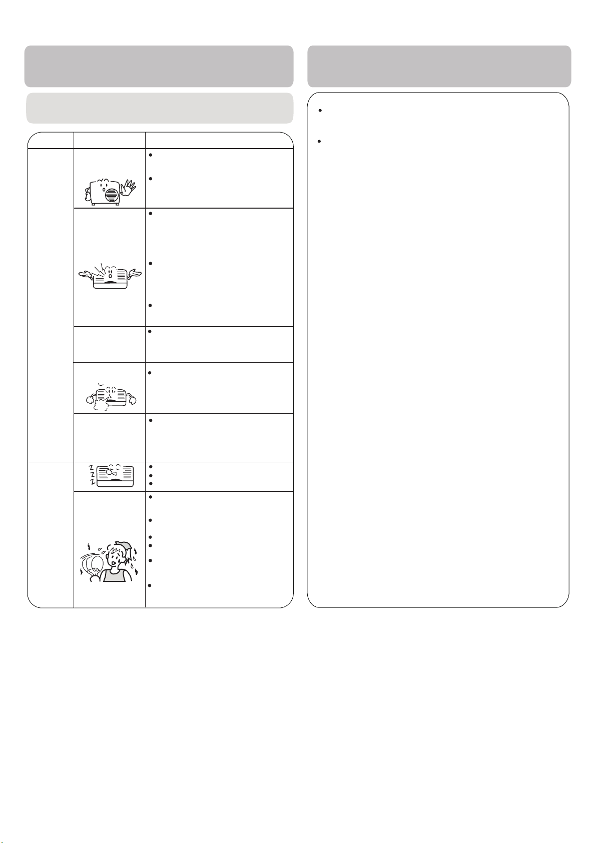
Noise is heard
Phenomenon Cause or check points
The system
immediately.
Smells are
generated.
Mist or steam are
Multiple
check
Poor cooling
When unit is stopped, it won't restart
elapsed to protect the system.
When the electric plug is pulled out
and reinserted, the protection circuit
During COOL or DRY operation,
This is due to the sudden cooling
Is power ON? Is there a power
failure?
Is the circuit breaker tripped?
In dry mode,
fan
speed can’t be
changed.
Is the air filter dirty?
Normally it should be cleaned
every 15 days during high use.
Are there any obstacles before
inlet and outlet?
Is temperature set correctly?
Are there some doors or
windows left open?
Is there any direct sunlight
through the window during the
cooling operation?
Is there too much heat sources
or too many people in the room
during cooling operation?
In DRY mode, when room temperature
becomes lower than set temp.
by 2 oC, the unit will run intermittently
at LOW speed regardless of FAN
setting.
indoor unit may blow out mist.
of indoor air.
This can be caused from the
system circulating smells from
the interior air such as the smell
of furniture, paint, cigarettes.
During unit operation or at stop,
a swishing or gurgling noise may
be heard. During the first 2-3 minutes
after unit start, this noise is more
noticeable. (This noise is generated by
refrigerant flowing in the system.)
During unit operation, a cracking noise
may be heard. This noise is
generated by the casing expanding
or shrinking because of
temperature changes.
Should there be a big noise from
air flow in unit operation, the air
filter may require cleaning.
will work for 3 minutes to protect the
air conditioner.
immediately until 3 minutes have
Cautions
Notes:
2. If the power supply cord is damaged, it must be replaced
manufacturer qualified
person.
or its service agent or a similar
3. The appliance must be installed by a qualified installer.
4. After installation, the power plug should be within reach.
5. Old batteries should be disposed correctly.
6. The appliance is not intended for use by young children or
infirm persons without supervision.
Trouble shooting
Before requesting for service, check the
following first.
blown out.
does not restart
by the
Do not obstruct or cover the ventilation
conditoner.Do not put fingers
inlet/outlet and swing louver.
This appliance is not intended for use by persons (including children)
with reduced sensory or mental capabilities or lack of experience
and knowledge, unless they have been given supervision or
instruction concerning use of appliance by a person responsible for
their safety. Children should be supervised to ensure that they do not
play with the appliance.
grille of the air
or any other objects into the
For warranty and service information, please refer to your separate
Warranty & Service booklet that came with the appliance
1. The appliance must be serviced and maintained regularly
by a qualified refrigeration mechanic. Failure to do so may
invalidate the warranty. Please refer to your Warranty and
Service booklet that came with the appliance for further
details.
7. If ever in doubt, switch of your appliance from the mains isolating
switch and seek advice or assistance from a professional person
such as your installer or our service department for assistance


 null")