manuals.online logo
Brands
  1. Home
  2. •
  3. Brands
  4. •
  5. Borglocks
  6. •
  7. Door Lock
  8. •
  9. Borglocks BL6100Mk4 Series User manual

Borglocks BL6100Mk4 Series User manual

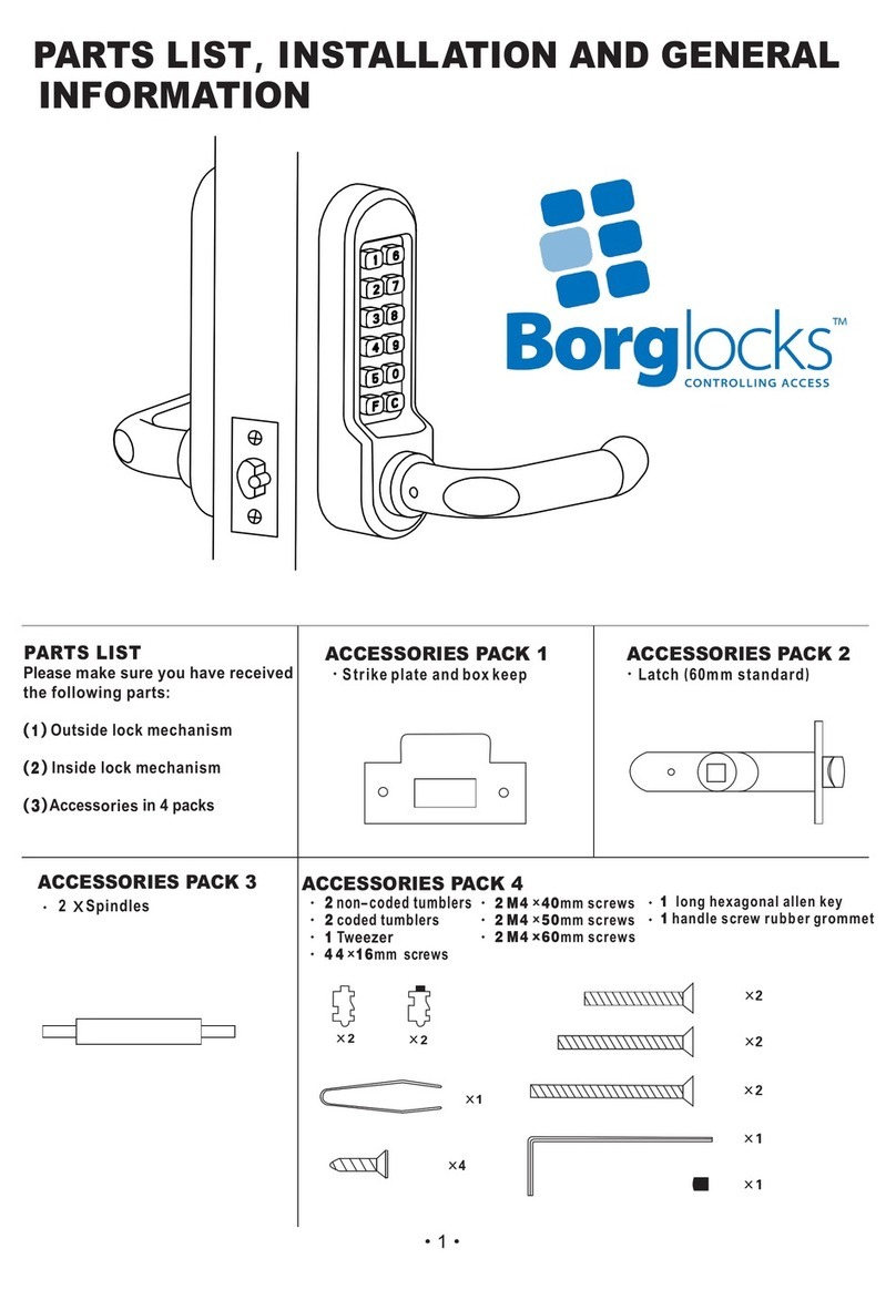
BL6100
Mk4 Series Instruction
Manual
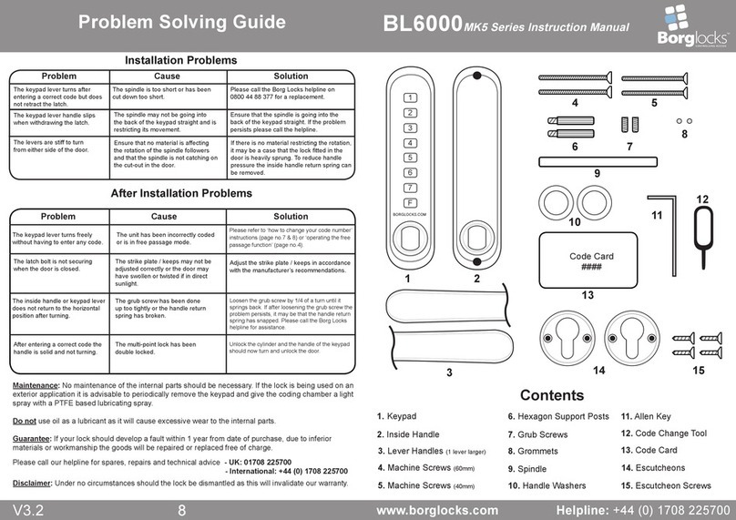
Problem Solving Guide
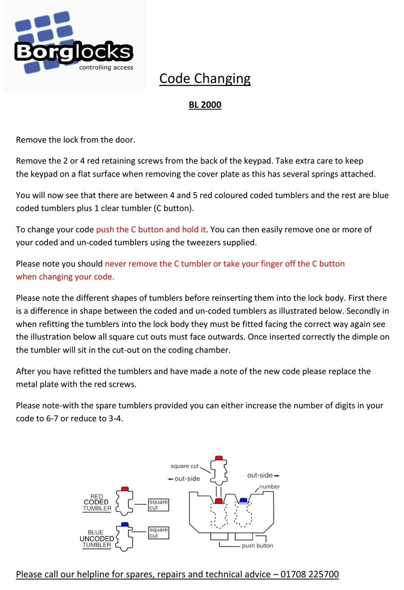
Maintenance: No maintenance of the internal parts should be necessary. If the lock is being used on an
exterior application it is advisable to periodically remove the keypad and give the coding chamber a light
spray with a PTFE based lubricating spray.
Do not use oil as a lubricant as it will cause excessive wear to the internal parts.
Guarantee: If your lock should develop a fault within 1 year from date of purchase, due to inferior
materials or workmanship the goods will be repaired or replaced free of charge.
Please call our helpline for spares, repairs and technical advice - UK: 0800 44 88 377
- International: +44 (0) 1708 225700
Disclaimer: Under no circumstances should the lock be dismantled as this will invalidate our warranty.
Problem Cause Solution
V1
Installation Problems
8
controlling access
Borglocks
Contents
After Installation Problems
Problem Cause Solution
The keypad lever turns freely
without having to enter any code.
The unit has been incorrectly coded
or is in free passage mode.
Please refer to ‘how to change your code number’
instructions (page no.7 & 8) or ‘operating the free
passage function’ (page no.4).
The inside handle or keypad lever
does not return to the horizontal
position after turning.
The grub screw has been done
up too tightly or the handle return
spring has broken.
Loosen the grub screw by 1/4 of a turn until it
springs back. If after loosening the grub screw the
problem persists, it may be that the handle return
spring has snapped. Please call the Borg Locks
helpline for assistance.
The latch bolt is not securing
when the door is closed.
The strike plate / keeps may not be
adjusted correctly or the door may
have swollen or twisted if in direct
sunlight.
Adjust the strike plate / keeps in accordance
with the manufacturer’s recommendations.
The keypad lever turns after
entering a correct code but does
not retract the latch.
The spindle is too short or has been
cut down too short.
Please call the Borg Locks helpline on
0800 44 88 377 for a replacement.
After entering a correct code the
handle is solid and not turning.
The multi-point lock has been
double locked.
Unlock the cylinder and the handle of the keypad
should now turn and unlock the door.
The keypad lever handle slips
when withdrawing the latch.
The spindle may not be going into
the back of the keypad straight and is
restricting its movement.
Ensure that the spindle is going into the
back of the keypad straight. If the problem
persists please call the helpline.
The levers are stiff to turn
from either side of the door.
Ensure that no material is affecting
the rotation of the spindle followers
and that the spindle is not catching on
the cut-out in the door.
If there is no material restricting the rotation,
it may be a case that the lock tted in the
door is heavily sprung. To reduce handle
pressure the inside handle return spring can
be removed.
1
2
3
4
5
6
7
F
BORGLOCKS.COM
Code Card
####
9 10
13 14
15
16
17 18
19
20
1 2
3
3
87
4 5
6
11
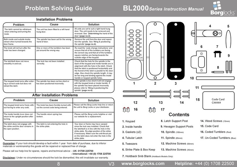
1. Keypad
2. Inside Handle
3. Lever Handles
4. Keypad Extension Plate
5. Inside Handle Extension Plate
6. Escutcheons
7. Keypad Retaining Screws (M5)
8. Inside Handle Retaining Screws (M4)
9. Machine Screws (80mm)
10. Machine screws (60mm)
11. Machine screws (40mm)
12. Machine screws (25mm)
13. Hexagon Support Posts
14. Grub Screws
15. Grommets
16. Spindle
17. Handle Washers
18. Allen Key
19. Code Change Tool
20. Code Card
12
2V1
Preparation How To Change Your Code Number
7
V1
6. With the selected marker in position the inner gear can be released. The tab of the inner gear will still be visible
(as per g.9) – using your nger rotate the coding disk around to the left / clockwise until you see the tab of the
inner gear drop down into the cut-out of the coding disk (as per g.10). Once the tab has dropped down rotate the
handle and you should see that the marker you have set is in alignment with the left hand arrow.
7. Once the rst digit has been set, the principle is the same for any other button that you want to set in the code.
Once you have programmed all the required digits in your code, turn the handle to reset the coding chamber and
ensure that all the buttons that are in the code have the coloured markers in alignment with the left hand arrow on
the keypad cover plate. Make sure that any digit that is not in the code has the blue marker of the coding disk in
alignment with the left hand arrow.
Hints & Tips
If you look on the top edge of each coding disk you will see that there are 3 cutouts. Furthest to the right cutout
(green) – for a two button press, centre cutout (Red) - for a single button press and furthest to the left cutout (blue)
- for a button not in the code. The tab of the inner gear needs to sit in one these cutouts.
Please check that all parts are working correctly. Once the lever handles have been tted to the keypad and inside
handle, enter the factory preset code as printed on the code card (part no.20), rotate the lever handle on the keypad
downwards, re-enter the code and turn the handle upwards ensuring that the spindle follower on the back of the
keypad rotates each time - an audible click should be heard every time a correct code is entered and the lever
handle is turned.
Both lever handles on the keypad and inside handle should return easily under their own spring pressure. Please
refer to ‘tting the lever handles’ below.
If you intend to change the code please refer to ‘how to change your code number’ instructions (pages no.7 & 8)
prior to tting.
Determining the Hand of the Door
Many of the installation instructions refer to the handing
of the door. The hand of the door is determined with the
door in its closed position from the exterior or keypad
side of the door, as shown in the diagram on the right.
A) Right hand door – door opens inward (push), hinged
on the right side.
B) Left hand door – door opens inward (push), hinged
on the left side.
C) Right hand inward opening – door opens outward
(pull), hinged on the right side.
D) Left hand inward opening – door opens outward
(pull), hinged on the left side.
Fitting the Lever Handles
The unit is non-handed and the lever handles (part no.3) are not supplied tted. Once you have determined what
handing of door you have, the lever handles can be tted to the keypad and inside handle. This is done as follows:
Ensure that one of the handle washers (part no.17) is placed around the handle holder before the handle is
secured in place with one of the grub screws (part no.14) and tightened using the allen key (part no.18).
With the lever handles secured to the keypad and inside handle turn the lever handle upwards and
downwards to ensure that they return under their own spring pressure to the horizontal position. If both lever
handles return under their own spring pressure cover the grub screw holes with the grommets (part no.15).
If the handle does not return under its own spring pressure loosen the grub screw by 1/4 of a turn until it springs
back. If loosening the grub screw does not allow the handle to spring back, it may be that one or more of the handle
washers (part no.17) needs to be removed.
1
2
3
4
Tab
Dropped
Down
Left Hand
Arrow
Fig.10
↓ ↓
Fig.7
1
2
3
4
Set as double press
Green Marker
↓ ↓
1
2
3
4
Set as single press
Red Marker
Fig.6
↓ ↓
1
2
3
4
Tab
Rotate
Left
Fig.9
↓ ↓
1
2
3
4
Not in the code
Blue Marker
Fig.8
↓ ↓
Inside
Outside
A B
CD
V1 3V1
Preparation
6
How To Change Your Code Number
Please note: The keypad has a double button press function and therefore you are able to have the same digit
twice. When the unit is being coded, if the green marker of the coding disk is in alignment with the left hand arrow
on the cover plate it denotes that the button is set as a double press. If the red marker of the coding disk is in
alignment with the left hand arrow it is set for a single press and if blue marker of the coding disk is in alignment
with the left hand arrow it is not part of the code.
The coding chamber is non-sequential so the code can be entered in any order. If for instance the unit was coded
to 1124 (as per g.4 below), the unit can be opened by entering 1142, 4211, 1214 etc...
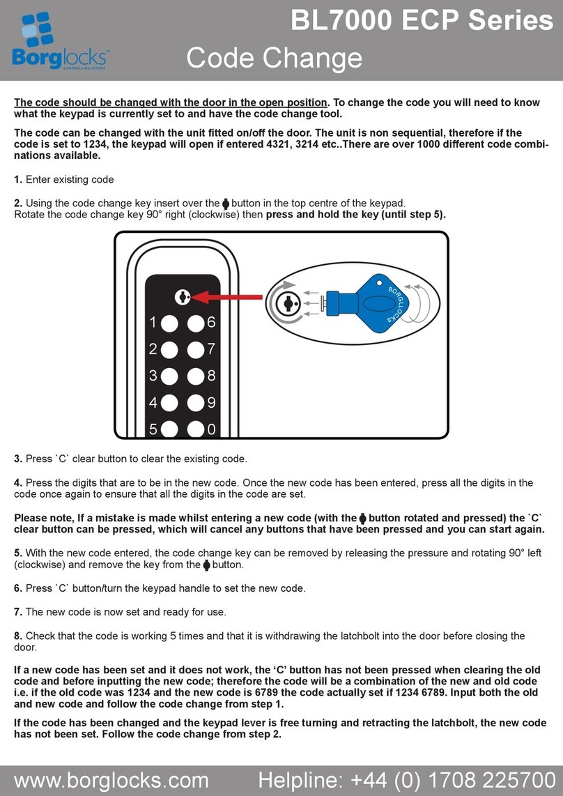
1. Remove the keypad from the door, this is done by removing the machine screws located at the top and bottom
of the inside handle.
2. With the keypad and inside handle removed from the door, turn the keypad over and remove the extension plate
so that the coding chamber is visible. The extension plate is secured to the keypad by 2 x retaining screws. Turn
the lever handle of the keypad to ensure that the coding chamber is reset before a new code is to be programmed.
3. With the coding chamber reset you will see that the coding disks are set to what the keypad is currently coded
to. If for instance the unit is coded to 1124; the number 1 disk will have the green marker of the coding disk lined up
with the left hand arrow on the cover plate. The number 2 and 4 will have the red marker of the coding disks lined
up with the left hand arrow (as per g.4). All the other coding disks will have the blue line in alignment with the left
hand arrow.
4. Decide what the unit wants to be code to. To change how a button is set in the code – this is done by using a
small amount of upwards force lifting the inner gear using the code change tool (part no.19) until the tab on the
inner gear becomes visible (as per g.5).
5. Whilst holding the inner gear the coding disk can be rotated using your nger. If you want that button in the code
as a single press align the red marker of the coding disk with the right hand arrow (as per g.6). If you want that
button as a double press align the green marker of the coding disk with the right hand arrow (as per g.7) and if
you do not want that button in the code align the blue line of the coding disk with the right hand arrow (as per g.8).
Fitting the Hexagonal Support Posts
Fit both of the hexagonal support posts (part no.13) into the top and bottom
threaded holes of the back of the keypad extension plate (part no.4), as shown
in arrows A and Bin the diagram on the right.
Without the hexagonal support posts tted the machine screws will not be able
to be screwed into place, as they are different thread sizes.
Do not over tighten the hexagonal support posts as this may strip the
thread on either the post itself or the thread in the extension plate.
How To Change Your Code Number
1
2
3
4
Left Hand
Arrow
Right Hand
Arrow
Fig.4
↓ ↓
1
2
3
4
Code Change
Tool
Tab Inner
Gear
Coding
Disk
Fig.5
↓ ↓
Preparation
Turning off the Free Passage Function
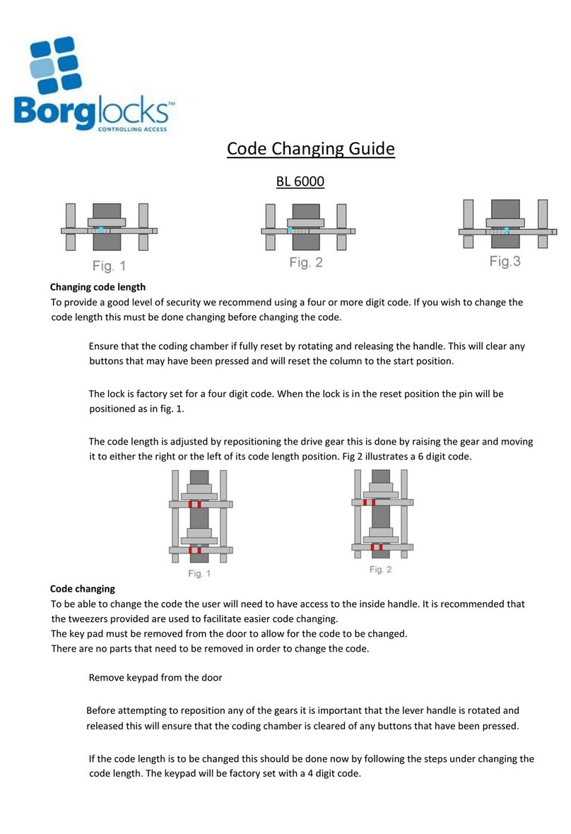
All units are supplied with the free passage function ready to be used, unless you have specically ordered with the
function turned off. If you do not require the free passage function this feature can be turned off, this should be done
before the unit is tted to the door.
If your unit has the free passage function turned on, the white line of the ‘F’ coding disk will be in alignment with the
left hand arrow (as per g.1). If it is turned off the blue line of ‘F’ coding disk will be in alignment with the left hand
arrow.
1. To turn off the free passage function – this is done by using a small amount of upwards force lifting the inner gear
using the code change tool (part no.19) until the tab on the inner gear becomes visible (as per g.2).
2. Whilst holding the inner gear the coding disk can be rotated using your nger. Rotate the disk until the blue line of
the coding disk is in alignment with the right hand arrow (as per g.3).
3. With the blue line in position the inner gear can be released. The tab of the inner gear will still be visible (as per
g.3) – using your nger rotate the coding disk around to the left / clockwise until you see the tab of the inner gear
drop down into the cut-out of the coding disk.
4. Once the tab has dropped down rotate the handle and you should see that the blue marker is in alignment with the
left hand arrow. If the blue line is in alignment the unit has the free passage function turned off.
If at a later date you wish to turn back on the free passage function, follow the above 4 steps but instead of setting
the blue line of the coding disk set the white line.
Rotate
Left
7
F
↓ ↓
Fig.3
7
F
↓ ↓
Fig.2
Tab
Code
Change
Tool
7
F
↓ ↓
Fig.1
Left Hand
Arrow
Right Hand
Arrow
Coding
Disk
B
A
4V1
Preparation & Installation
5V1
Installation & Operation
Fitting Illustration
Apply the Drilling Template
If the unit is to be tted onto a UPVC door then the door section is likely to have
already been drilled out to accept a standard set of lever handles. In this case
please align our drilling template from the spindle centre with the spindle centre in
the door.
1. Apply the supplied template to the outside of the door so that the centre line of
the keypad matches the backset of the latch taking into account that most UPVC
doors have a rebated edge.
2. Mark the centres points for the top and bottom xing holes and the hole for the
spindle and drill to the correct size holes as specied on the drilling template.
Operating the Free Passage Function
When the keypad is set in the free passage function the handle will be free turning until the function is deactivated.
This function is designed for high trafc / low security situations and allows users to pass through the door by
turning the handle without having to enter the code each time.
The ‘F’ button activates the free passage function, if you want to set this function the steps are as follows:
1. Enter the code into the keypad along with the ‘F’ button and turn the handle.
2. The user will now be able to rotate the handle freely without having to enter the code.
3. To cancel the free passage function, press the ‘F’ button and rotate the keypad handle once and the keypad will
return to being in the locked state.
Door
Hexagon
Support Posts
(part no.6)
Spindle
(part no.16)
Machine Screws
(part no. 9/10/11/12)
Lever Handle
(part no.3)
Lever Handle
(part no.3)
Handle Washer
(part no.17) Handle Washer
(part no.17)
Keypad
(part no.1)
Inside Handle
(part no.2)
Fitting & Positioning the Spindle
If the spindle needs to be cut to length, offer the keypad up to the
door and put the spindle into the back of the keypad. The ideal length
of spindle protruding to go into the back of the inside handle wants to
be between 10-15mm. There is a spring located in the spindle
follower of the inside handle to avoid any movement of the spindle
when tted to the door.
If the spindle is cut too short there is a chance the spindle could
slip out of position and result in the user being locked out.
Operating the Unit
The 6000 series model has been designed to work with a variety of multi-point locks and how they work varies
between different manufacturers. In the majority of cases, if the door is double locked via a key, the keypad or
inside handle will not operate until it has been unlocked.
Before entering a code turn the handle to ensure the coding chamber is clear of any buttons that may have been
pressed. Enter the code and turn the handle, the latchbolt and any other secondary bolts will disengage and the
door will open. After the handle is turned the unit will reset and the code will need to be entered again in order to
access. If there is going to be constant trafc through the door you may want to put the unit in free passage mode,
please refer to ‘operating the free passage function’ on page 4.
If tted to a multi-point lock and the door needs to be double locked, enter the code and lift the handle upwards this
will throw any secondary bolts and the key can be turned to double lock.
Back of Keypad
Spindle
(part no.9)
Spindle
Follower
Inside Handle
Retaining Screw M4
(part no.8)
Machine Screws
(part no.9/10/11/12)
Hexagon Support Posts
(part no.6)
M5 keypad
Retaining Screw
(part no.7)
M5 keypad
Retaining Screw
(part no.7)
Escutcheon
(part no.6)
Escutcheon
(part no.6)
Keypad
Extension Plate
(part no.4)
Inside Handle
Extension Plate
(part no.5)
Fitting the Extension Plates & Escutcheons
The keypad (part no.1) is secured to the keypad extension plate (part no.4) by the keypad retaining screws M5
(part no.7). When attaching the extension plate to the keypad, ensure that countersunk holes are facing away from
the back of keypad to allow the screws to sit ush when tightened.
With the extension plate tted, the escutcheon (part no.6) can be put into place. The escutcheons are oval in pro-
le and are to suit 70mm and 72mm centre locks and ipping the escutcheon over allow it to suit 90mm and 92mm
centre locks. To secure the escutcheon to the extension plate there are two tabs of double-sided tape on recessed
edge of the extension plate. Peel the cover off the tape and put the escutcheon into the recess.
The tting of the escutcheon is the same for the inside handle extension plate. When the two extension plates are
tted to the door, the escutcheons will be sandwiched into place. With the pair of extension plates tted the inside
handle can be secured to its extension plate using the two inside handle retaining screws M4 (part no.5).
Door
Inside Handle
Retaining Screw M4
(part no.8)

Other Borglocks Door Lock manuals

Borglocks BL 6000 Administrator guide

Borglocks

Borglocks BL 6000 Administrator guide

Borglocks BL5000 ECP User manual

Borglocks

Borglocks BL5000 ECP User manual

Borglocks BL 2000 User manual

Borglocks

Borglocks BL 2000 User manual

Borglocks BL7000 ECP Series Administrator guide

Borglocks

Borglocks BL7000 ECP Series Administrator guide

Borglocks BL2000 Series User manual

Borglocks

Borglocks BL2000 Series User manual

Borglocks BL5001 Service manual

Borglocks

Borglocks BL5001 Service manual

Borglocks BL5000 Configuration guide

Borglocks

Borglocks BL5000 Configuration guide

Borglocks BL3100 ECP Series User manual

Borglocks

Borglocks BL3100 ECP Series User manual

Borglocks MK5 Series User manual

Borglocks

Borglocks MK5 Series User manual

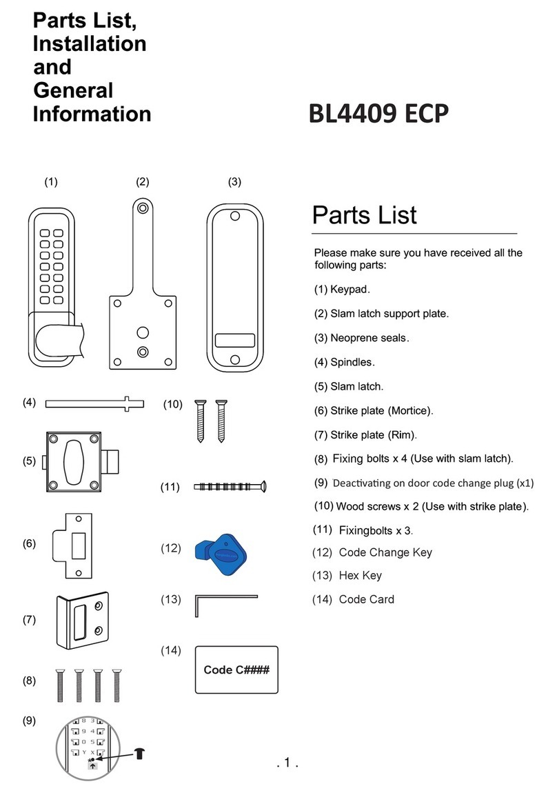
Borglocks BL4409 ECP Configuration guide

Borglocks

Borglocks BL4409 ECP Configuration guide

Popular Door Lock manuals by other brands

Digilock Next Lock Range Standard Product guide

Digilock

Digilock Next Lock Range Standard Product guide

Nice Sele & Seli Instructions and warnings

Nice

Nice Sele & Seli Instructions and warnings

Kaba E-Plex 5900 Installation

Kaba

Kaba E-Plex 5900 Installation

DynaLock 3002 TJ32 Series installation instructions

DynaLock

DynaLock 3002 TJ32 Series installation instructions

CISA SIKUREXIT 43295 Series instruction sheet

CISA

CISA SIKUREXIT 43295 Series instruction sheet

WALA WU 1R MB45 Assembly instructions

WALA

WALA WU 1R MB45 Assembly instructions

Lockly ACCESS TOUCH PRO installation guide

Lockly

Lockly ACCESS TOUCH PRO installation guide

Assa Abloy SARGENT Profile Series installation instructions

Assa Abloy

Assa Abloy SARGENT Profile Series installation instructions

Conrad Electronic 751549 operating instructions

Conrad Electronic

Conrad Electronic 751549 operating instructions

DOM Tronic Pro Assembly

DOM

DOM Tronic Pro Assembly

Dormakaba c-lever pro Technical manual

Dormakaba

Dormakaba c-lever pro Technical manual

Dormakaba Saffire LX installation instructions

Dormakaba

Dormakaba Saffire LX installation instructions

Gretsch-Unitas GU-SECURY Automatic with A-opener Assembly and operating instructions

Gretsch-Unitas

Gretsch-Unitas GU-SECURY Automatic with A-opener Assembly and operating instructions

Alarm Lock 700 SERIES instructions

Alarm Lock

Alarm Lock 700 SERIES instructions

Weiser Kwikset 60729 instructions

Weiser

Weiser Kwikset 60729 instructions

CODELOCKS CL610 Guide

CODELOCKS

CODELOCKS CL610 Guide

Schlage Ease S2 quick start guide

Schlage

Schlage Ease S2 quick start guide

Securemme DSMART instruction manual

Securemme

Securemme DSMART instruction manual

manuals.online logo
manuals.online logoBrands
  • About & Mission
  • Contact us
  • Privacy Policy
  • Terms and Conditions

Copyright 2025 Manuals.Online. All Rights Reserved.