Ref: CSP-TR800-433BM-20111202.doc Bosch™ Compatible 433MHz Receiver for use with Livewire Relay Boards
PCB: Rev B.C, S/W: Ver 1.23 Page 1
Cat: TR800-433BM
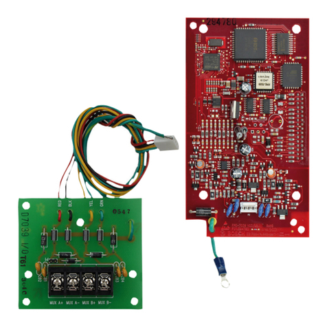
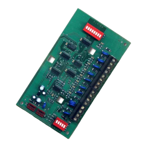
Radio Receiver Module, 433MHz BOSCH™ Compatible
Fits to Relay Boards (RLDP-V, RLSPHC-V)
1.0 Overview
433MHz radio receiver.
Compatible with Bosch™ series keyfob alarm transmitters.
Plugs on to Livewire RLDP-V or RLSPHC-V relay boards.
Two outputs: (1) relay on relay board and (2) logic level output.
Remote trigger input for wired pushbutton control.
2.0 Specifications
Parameter Description
Dimensions (mm) 36w x 9d x 18h
Frequency 433.42MHz
Modulation ASK
Compatible keyfob
transmitters (a) Bosch™ RF3332E, RF3334E
(b) Connect T433B.
Compatible relay
boards (a) Livewire RLDP-V
(b) Livewire RLSPHC-V
Outputs (a) 2 (one relay, one logic level)
Output timers (a) Seconds: 1-255
(b) Minutes: 1-100
Max number
learned transmitters 16
Operating temp 0 deg C – 55 deg C
Operating voltage 12VDC (11.5V min, 13.8V max)
Operating current (a) Relay off: 24mA
(b) Relay on: 35mA
Programmed keyfobs and timer values retained during power down.
8.0 Switch Settings, Receiver Mode and Outputs
Sw Function Off (0) On (1) Default Note
S1 TP TP=OUT2 TP=Remote
Trigger Input Off 1, 2
S2 Unused Off
S3 Ch Mode See Output Channel Mode
table Off
S4 Ch Mode Off
Note 1: When used as Remote Trigger Input, triggered on negative
edge. Pulled high via 10k to 3.3V.
Note 2: When used as second output (OUT2), TP is connected to
Microcontroller (3.3V), positive logic via 470R (max 7mA).
Output Channel Mode Table
Switches S3 and S4 set the mode of operation for the two outputs.
Setting S3=On and S4=On is a special case where transmitter
buttons force channel outputs on or off as shown. These button
settings override the learned button order but if S3/S4 are changed
back to Pulse/Toggle, the stored button settings will again be used.
S3 S4 OUT1 OUT2 OUT3 OUT4
Off Off Pulse Pulse Pulse Pulse
Off On Toggle Toggle Toggle Toggle
On Off Pulse Toggle Pulse Toggle
On On B2:
OUT1 On B1:
OUT1 Off B3:
OUT2 On B4:
OUT2 Off
Note: Buttons B1-B4 refer to Keyfob Transmitter T433B below.
3.0 Setting Pulse Output Time (Default: 2 Secs)
To set the pulse output time:
a) Remove power.
b) Press LEARN button.
c) Apply power, still holding LEARN. LED will light then turn off
when ready to count pulses.
d) Press LEARN ‘x’ times to set the pulse output time to ‘x’. LED
flashes once per push.
e) After entering the desired pulse output time, set the units:
(i) Seconds: Do nothing, the heartbeat will restart and the
timer will be set in units of seconds. Range 1-255s.
(ii) Minutes: Press and hold LEARN. When LED lights solid,
release. Units will be set to minutes. Range 1-100m.
If no button press is detected within 5 secs, pulse count mode is
aborted and TR800-433B returns to normal receive mode.
4.0 Remote Trigger Input (TP)
For wired pushbutton control. When enabled, the Remote Trigger
Input is active on TP. Shorting TP to ground causes the relay to
operate as if the appropriate keyfob transmitter button was pressed.
To enable, set DIPSW S1 ON (See also Section 14.0).
5.0 Second Output (OUT2 on TP)
When enabled, the second output is active on pin TP.
Off=0V, On=3.3V.
To enable, set DIPSW S1 OFF (See also Section 14.0).
6.0 Compatible Transmitters
The following keyfobs are compatible with the TR800-433BM. Also
operates with external input on point transmitter RF3401E.
T433B RF3332E, RF3334E
7.0 Learning Transmitters, Assigning Relays to Buttons
Keyfobs can be learned into the TR800 and buttons assigned to the
output(s).
To learn a transmitter (i.e., assign one or more buttons to outputs):
1. Press LEARN button for 1 second until LED goes off, release.
2. To assign single button to OUT1, press desired button once.
Press same button again.
3. To assign two buttons to two outputs, press desired button for
OUT1 followed by desired button for OUT2.
4. Note that Force mode will operate for any learned transmitter.
Once a transmitter is learned, the output assigned to the button will
operate in accordance with the switch settings in Section 3.0.
