D9133TTL-E |Installation Guide | 3.0 Installation
.
Bosch Security Systems, Inc. | 6/07 | 4998122717-01 7
3.1.3 Mounting in a Separate Enclosure
If so desired, the D9133TTL-E can be mounted in a
separate enclosure like the AE1 (Grey) or the AE2
(Red). For other enclosures, please see the
instructions for panel to be used. The separate
enclosure to be used must be UL Listed for Fire
Applications and no other equipment is to be
present.
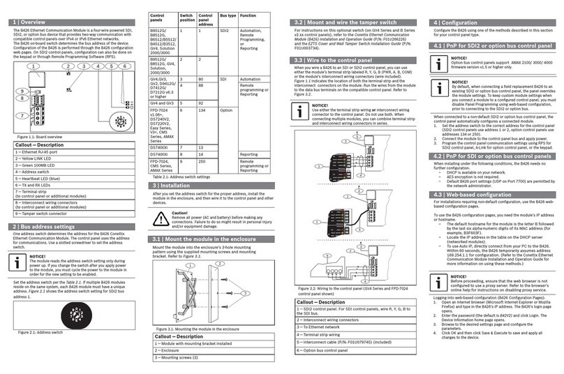
To install a D9133TTL-E in an AE2 enclosure, refer
to Figure 7.
Figure 7: Mounting the D9133TTL-E in a
AE1/AE2 Enclosure
A
1
234
5
6
7
8
1 - Enclosure top slot (detail)
2 - D9133TTL-E
3 - Enclosure top slot
4 - Mounting screws (2)
5 - Bottom mounting holes
6 - Top plastic standoffs
7 - Mounting Bracket (detail)
8 - Mounting brackets
It is recommended that the enclosure be
mounted on a vertical surface before
installing the module. When the module is
installed, one of the enclosure mounting
holes (item A in Figure 7) will be covered
by the module.
1. Place the top edge of the D9133TTL-E module
between the two slots on the inside top of the
enclosure.
2. Insert the top hook of the top plastic standoffs
into the mounting brackets on the back wall of
the enclosure.
3. Line up the bottom two mounting holes on the
D9133TTL-E with the plastic standoffs and the
enclosure mounting brackets.
4. Insert two screws into the holes and slowly
tighten them until the D9133TTL-E is seated
firmly on the enclosure.
3.2 Wiring
The D9133TTL-E is specifically designed to work
with the Bosch control panels as an SDI bus device
(D9412GV2, D7412GV2, D7212GV2, D9412G,
D7412G, D7212G, D9412, D9112, D7412, and
D7212 with software version 6.30 or later). Refer to
Section 3.2.1 Connection Sequence (D9133TTL-E to Panel
in Separate Enclosure) for the proper connection
sequence.
Figure 8: Wiring the D9133TTL-E to a Bosch
control panel (in a separate
enclosure)
+
-
EARTHGROUND
COMMON
BATTERYNEGATIVEONLY
MaximumCharging
Current1.4 Am ps.
BATTERYPOSITIVEONLY
RELAYA
RELAYB
RELAYC
+AU X POWER
1
2
3
4
5
6
7
8
9
10
CLASS2 T RANSFORMER
16.5VAC 40 VA 60 Hz
PartNo. D1640
Internally Fused - Do No t short
RequiresUnsw itched Outlet
DoNotShareWithOtherEquipment
LEDs Off When Normal
ChargingStatus
LowBattery-12.1VDC
YEL
RED
PROGRAMMABLE
ALARMOUTPUTS
Terminals
Requires Optional
D136Relay
InALT ALARM
&SW AUX
&
78
GROUNDFAULTDETECT
Enabled
Disabled
PHONE
LED
RED
ONWHEN
COMMUNICATING
OFFWHEN IDLE
DigitalAlarm Communicator Transmitter
ReferenceMa nual #43494 ___ For System Wiring Diagram, I ssue A
ReferenceDocument#33284___For CompatibleSmokeDetectors
POWERSU PPLYRE QUIREMENTS
ThePower Supply Providesa Maximum of 1.4 Amps For The Control
Paneland All Accessory Devices. For System Loading, See Operation-
InstallationManual#43488___.
AllExternal Connections Exce pt Terminal 5 (Battery Positive) Are
InherentlyPowerLimited.
RequirementsF orB attery Standby Time May Reduce Allowable Output.
CAUTION: See Manual For Power Req uirements Relating to Terminals 6 7
WARN ING!
Multi-Battery Installa tion Requires
Model No. D122 D ual Battery Ha rness.
Improper Installati on Can Be a Fire
Hazard.
Battery: Replace Every 3 t o
5years withModel D126,12 V
7Am p Hr Lead Acid B attery
ThisequipmentshouldbeinstalledinaccordancewiththeNFPA70 (NationalElectricalCode)
andNFPA72 (National Fire Alarm Code) forL ocal,Central Station, RemoteStation and Household Fire
WarningSystemsand under the limits of the Local AuthorityHaving Jurisdiction (NationalF ire
ProtectionAssociation,Batterymarch Park, Quincy,MA 02269) Printedinformation describing proper
installation,operation, testing, mai ntenance,e vacuation planning and repair service is to be provided
withthisequipment.
D9412GControl / Communicator is UL ListedF or Central Station,Local, Re moteStation and Household
FireAlarm, and Central Station,Lo cal, PoliceStation Connect and Household Burglar Alarm.
Systemis Intended To Be Checked By AQ ualified TechnicianA t Least Every 3 Years.
Thetypes of in itiating circuits that the panel has been approved for are A, M, W, SS.
VOLTAGE RANG ES
Open 3.7-5 .0VDC
Normal 2.0 - 3.0 VDC
Short 0.0- 1.3 VDC
GRN
ResetPin
DisableAllExceptBattery
ChargingAndProgramming
PERIPHERALDEVICECONNECTIONS
RED POWER +
YELLOW DATA BUS A
GREEN DATA BUS B
BLACK COMMON
ZONEXOUT1
ZONEXIN 1
N.F.P.A.
Style3.5
Signaling
Line
Circu its
32
31
30
29
28
27
PROG
CONN
43489F
LOOPS TART
PHONEMONITORSE LECT
Point8
GNDFAULT
Detec t
E
N
A
B
L
E
D
I
S
A
B
L
E
ZONEXOUT2 26
25
ZONEXIN 2
ZONEX POWER + 24
ZONEX CO MMON 23
1211 13
Point 1 Poin t 2
1514 16
Point3 Point4
1817 19
Point 5 Point 6
2120 22
Point7 Point8
GROUND START
Requires
Relay# D 136 in
Ground
StartSocket
GNDSTART
10.2VDC - Battery Load S hed
Battery
2
1
4
3
6
7
5
1 - Bosch control panel – D9412G is shown
2 - D9133TTL-E Network Interface Module
3 - To LAN/WAN via Ethernet Controller
4 - AE1 Enclosure
5 - D8103 Enclosure
6 - Battery
7 - To AC Transformer
3.2.1 Connection Sequence (D9133TTL-E to
Panel in Separate Enclosure)
Follow the procedures below to correctly wire the
D9133TTL-E to the control panel.
