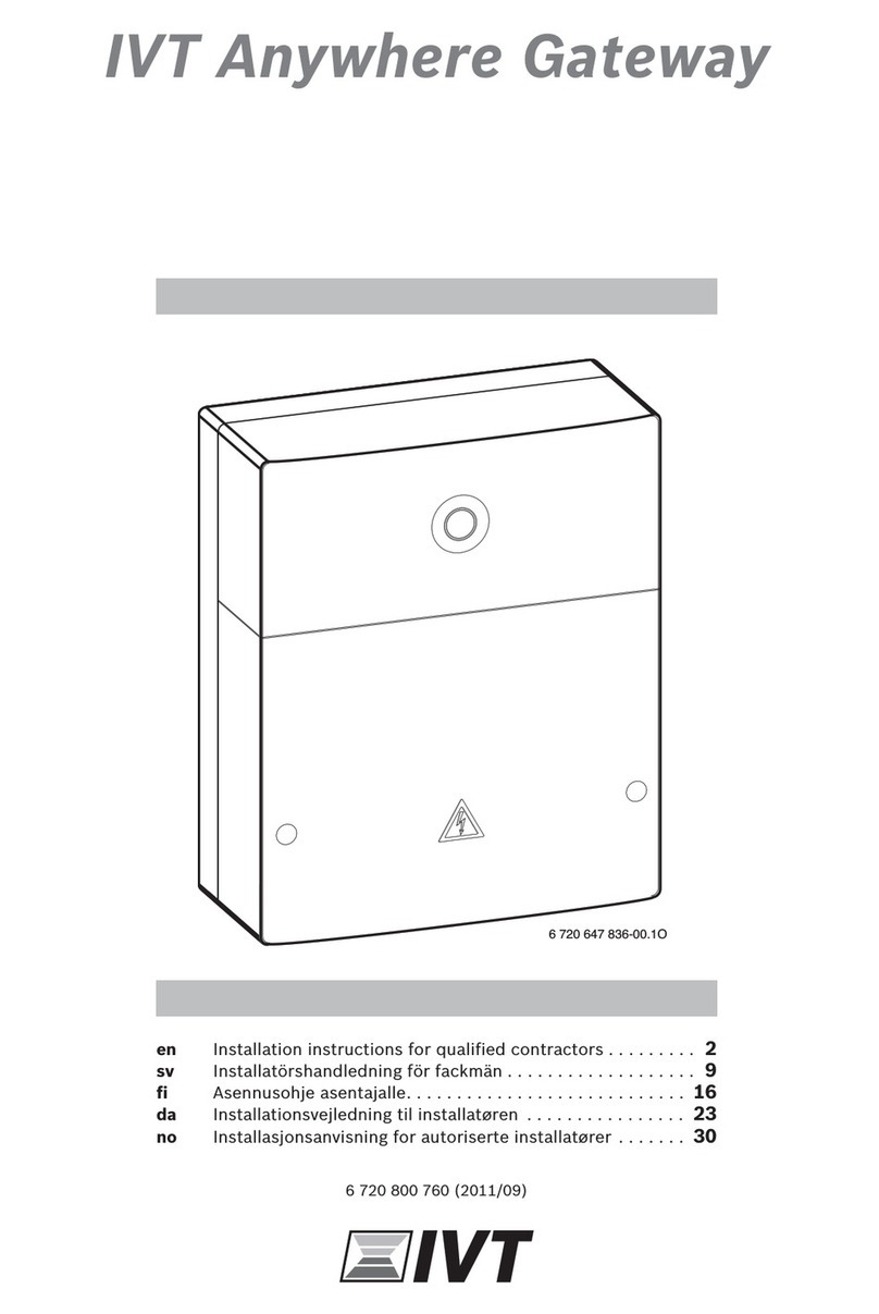
Bosch ProControl HP User manual
Other Bosch Gateway manuals
Bosch
Bosch MB LAN 2 User manual

Bosch
Bosch CLIMATE 5000 VRF RDCI Series Instruction Manual

Bosch
Bosch MB LAN 2 User manual
Bosch
Bosch Conettix D6600 User manual

Bosch
Bosch Conettix D6600 Operating instructions

Bosch
Bosch Conettix D6600 User manual
Bosch
Bosch ConnectS2 User manual

Bosch
Bosch Conettix D6600 Operating instructions

Bosch
Bosch CLIMATE 5000 VRF RDCI Series User manual
Bosch
Bosch FWI-270 User manual
Bosch
Bosch ProControl User manual
Bosch
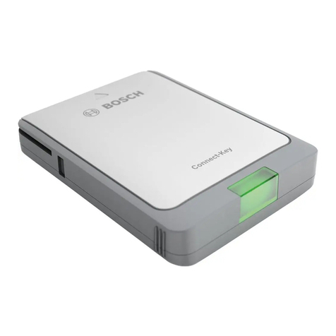
Bosch Connect S User manual
Bosch
Bosch K 30 RF User manual

Bosch
Bosch FWI-270 User manual
Bosch
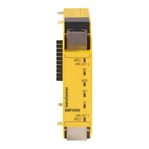
Bosch Rexroth IndraControl SafeLogic... User manual

Bosch
Bosch Conettix D6600 Operating instructions
Bosch
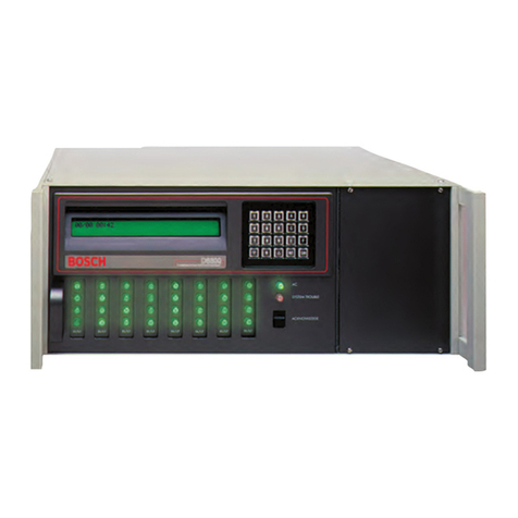
Bosch Conettix D6600 Quick start guide
Bosch
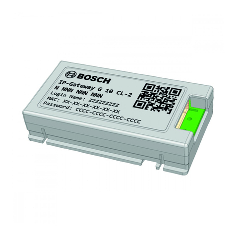
Bosch G 10 CL-2 User manual

Bosch
Bosch Conettix D6600 Operating instructions
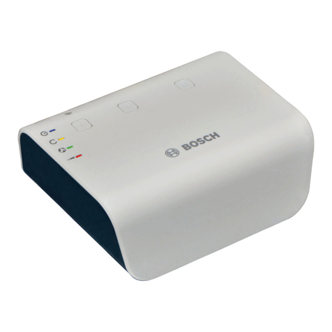
Bosch
Bosch G100 Operating instructions
Popular Gateway manuals by other brands

LST
LST M500RFE-AS Specification sheet

Kinnex
Kinnex Media Gateway quick start guide

2N Telekomunikace
2N Telekomunikace 2N StarGate user manual

Mitsubishi Heavy Industries
Mitsubishi Heavy Industries Superlink SC-WBGW256 Original instructions

ZyXEL Communications
ZyXEL Communications ZYWALL2 ET 2WE user guide

Telsey
Telsey CPVA 500 - SIP Technical manual
