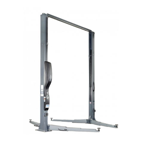
Bosch VLH 2235H User manual

VLH 2235H
en
Original instructions
zh
操作手册
2-post lifts 2柱举升机


6 000 836 999 2013-05-08| Bosch Automotive Diagnostics Equipment (Shenzhen) Limited
4 | VLH 2235H | en
Contents
1. Symbols used 5
1.1 In the documentation 5
1.1.1 Warning notices -
Structure and meaning 5
1.1.2 Symbols in this documentation 5
1.2 On the product 5
2. Important notes 7
3. Safety instructions 7
3.1 Mains voltage 7
3.2 Risk of injury, danger of crushing 7
4. Obligations of the plant operator 8
4.1 Operation of lifting platforms 8
4.2 Checking of lifting platforms 8
4.2.1 Scope of checking 8
4.2.2 Regular checking 8
4.2.3 Exceptional checking 8
5. Product description 9
5.1 Intended use 9
5.2 Authorized users 9
5.3 Product versions 9
5.4 Special accessories 9
5.5 Transportation information 9
5.6 Set-up and initial commissioning 10
5.7 Preparation by the user 10
5.7.1 Space requirements 10
5.7.2 Foundation and connections 10
5.8 Description of unit 10
5.8.1 Outline 10
5.8.2 Lifting mechanism 11
5.8.3 Support arms 11
5.8.4 Support plate and spacer sleeves 12
5.8.5 Operating unit 12
5.9 Safety features 12
6. Operation 13
6.1 Important notes on operation 13
6.2 Switch-on 13
6.3 Preparation 13
6.4 Vehicle positioning 13
6.5 Vehicle lifting 14
6.6 During work on vehicle 14
6.7 Vehicle lowering 14
6.8 Driving the vehicle out 14
6.9 Switch-off 14
7. Faults 15
7.1 Faults during lifting platform operation 15
8. Maintenance 16
8.1 Important notes on maintenance 16
8.2 Cleaning 16
8.3 Replacement and wearing parts 16
8.4 Maintenance by the user 16
8.4.1 Maintenance agreement 16
8.4.2 Maintenance schedule 17
9. Decommissioning 17
9.1 Temporary shutdown 17
9.2 Change of location 17
9.3 Disposal and scrapping 17
9.3.1 Substances hazardous to water 17
9.3.2 VLH 2235H and accessories 17
10. Technical data 18
10.1 Ambient conditions 18
10.1.1 Use 18
10.1.2 Storage and transportation 18
10.2 Performance data 18
10.2.1 Lifting platform 18
10.3 Operating data 18
10.3.1 Electric power 18
10.3.2 Hydraulic system 18
10.4 Noise emissions 18
10.5 Dimensions and weight 18
10.6 Support arms 18
10.6.1 Short support arms 18
10.6.2 Long support arms 18
10.7 Electromagnetic compatibility (EMC) 18

6 000 836 999 2013-05-08| Bosch Automotive Diagnostics Equipment (Shenzhen) Limited
Symbols used | VLH 2235H | 5VLH 2235H | 5 | 5 en
1. Symbols used
1.1 In the documentation
1.1.1 Warning notices - Structure and meaning
Warning notices warn of dangers to the user or people in
the vicinity. Warning notices also indicate the consequenc-
es of the hazard as well as preventive action. Warning no-
tices have the following structure:
Warning
symbol KEY WORD – Nature and source of hazard!
Consequences of hazard in the event of fail-
ure to observe action and information given.
¶Hazard prevention action and information.
The key word indicates the likelihood of occurrence and
the severity of the hazard in the event of non-observance:
Key word Probability of
occurrence
Severity of danger if in-
structions not observed
DANGER Immediate impend-
ing danger
Death or severe injury
WARNING Possible impending
danger
Death or severe injury
CAUTION Possible dangerous
situation
Minor injury
1.1.2 Symbols in this documentation
Symbol Designation Explanation
!Attention Warns about possible property damage.
iInformation Practical hints and other
useful information.
1.
2.
Multi-step
operation
Instruction consisting of several steps.
eOne-step
operation
Instruction consisting of one step.
Intermediate
result
An instruction produces a visible inter-
mediate result.
"Final result There is a visible final result on com-
pletion of the instruction.
DANGER – Exposure of live parts on open-
ing the VLH 2235H!
Risk of (fatal) injury or heart failure from elec-
tric shocks on contact with live components
(e.g. main switch, printed circuit boards).
¶Work on electrical installations or equip-
ment is only to be performed by qualified
electricians or trained personnel under the
guidance and supervision of an electrician.
¶Disconnect the VLH 2235H from the mains
before opening.
Disposal
Dispose of used electrical and electronic
devices, including cables, accessories and
batteries, separately from household waste.
1.2 On the product
!Observe all warning notices on products and ensure
they remain legible.

6 000 836 999 2013-05-08| Bosch Automotive Diagnostics Equipment (Shenzhen) Limited
6 | VLH 2235H | Symbols useden
Riding on the support arms or in the vehicle is
prohibited.
Warnings in brief
Fig. 1: Warnings in brief
1 Clear area if vehicle is in danger of falling
2 Position vehicle with center of gravity midway between adapter
3 Remain clear of lift when raising or lowering vehicle
4 Avoid excessive rocking of vehicle while of lift
5 Don’t override self- closing lift control
6 Keep feet clear of lift vehicle lowering
Cautions in brief
Fig. 2: Cautions in brief
1 Lift by use trained operator only
2 Authorized personnel only in lift area
3 Use vehicle manufacturer’s lift points
4 Always use safety stands when removing or installing heavy com-
ponents
5 Use height extenders when necessary to ensure good contact
6 Auxiliary adapters may reduce load capacity
Instructions in brief
Fig. 3: Instructions in brief
1 Read operating and safety manuals before using lift
2 Proper maintenance and inspection is necessary for safe opera-
tion
3 Do not operate a damaged lift

6 000 836 999 2013-05-08| Bosch Automotive Diagnostics Equipment (Shenzhen) Limited
Important notes | VLH 2235H | 7VLH 2235H | 7 | 7 en
Use of the product constitutes acceptance of the fol-
lowing conditions:
Copyright
The enclosed instructions are the property of Bosch
Automotive Diagnostics Equipment (Shenzhen) Limited
or its suppliers and are protected against reproduction
by copyright laws, international agreements and other
national legal stipulations. The reproduction or disposal
of instructions or excerpts thereof is impermissible and
constitutes an offence. In the event of contravention,
Bosch Automotive Diagnostics Equipment (Shenzhen)
Limited reserves the right to take legal action and as-
sert claims for damages.
Warranty
The use of non-approved hardware causes changes to
our products and thus results in the exclusion of any
liability and warranty claims, even if the hardware has
been removed again in the meantime.
It is not permissible to make any changes to our
products and these are only to be used together with
genuine accessories and genuine replacement parts.
Otherwise any warranty claims will be invalid.
Liability
Liability on the part of Bosch Automotive Diagnostics
Equipment (Shenzhen) Limited is limited to the amount
actually paid by the customer for the product con-
cerned. This exemption from liability does not apply to
wilful damage or damage arising from gross negligence
on the part of Bosch Automotive Diagnostics Equip-
ment (Shenzhen) Limited.
2. Important notes
Before start up, connecting and operating
Bosch Automotive Diagnostics Equipment
(Shenzhen) Limited products it is absolute-
ly essential that the operating instructions/
owner’s manual and, in particular, the safety instruc-
tions are studied carefully. By doing so you can elimi-
nate any uncertainties in handling Bosch Automotive
Diagnostics Equipment (Shenzhen) Limited products
and thus associated safety risks upfront; something
which is in the interests of your own safety and will
ultimately help avoid damage to the device. When a
Bosch Automotive Diagnostics Equipment (Shenzhen)
Limited product is handed over to another person, not
only the operating instructions but also the safety
instructions and information on its designated use must
be handed over to the person.
3. Safety instructions
3.1 Mains voltage
Insulation damage and other faults may result
in accessible components being live.
Safety measures:
¶Only ever use the power cord provided or a tested
power cord.
¶Replace wires with damaged insulation.
¶Do not open the operating unit.
3.2 Risk of injury, danger of crushing
In the event of excessive vehicle weight, incor-
rect mounting of the vehicle or on removing
heavy objects, there is a risk of the vehicle falling
off the lifting platform or tipping up.
Safety measures:
¶The lifting platform is only ever to be employed for
the intended purpose.
¶Carefully study and heed all the information given in
Section 6.1.
¶Observe the warning notices for operation (Section 6).

6 000 836 999 2013-05-08| Bosch Automotive Diagnostics Equipment (Shenzhen) Limited
8 | VLH 2235H | Obligations of the plant operatoren
4. Obligations of the plant
operator
4.1 Operation of lifting platforms
In Germany, the use of lifting platforms is governed by
the mandatory "Employers' liability insurance associa-
tion regulations on health and work safety as defined in
BGR 500 Section 2.10". In all other countries, the ap-
plicable national regulations, laws and directives must
be observed.
4.2 Checking of lifting platforms
Checks are to be based on the following directives and
regulations:
RBasic principles for testing lifting platforms (BGG 945)
RThe basic health and safety requirements stipulated
in the directive 2006/42/EC
RHarmonized European standards
RThe generally acknowledged rules of engineering
RThe directive on the use of equipment 89/655/EEC
RThe applicable accident prevention regulations
RJT/T 155-2004 automobile lift
The checks are to be organized by the user of the lifting
platform. The user is responsible for appointing an ex-
pert or qualified person to perform checking. It must be
ensured that the person chosen satisfies the require-
ments of BGG 945 as per Section 3.
!The user bears special responsibility if employees of
the company are appointed as experts or qualified
persons.
4.2.1 Scope of checking
Regular checking essentially involves performing a visu-
al inspection and a functional test. This includes check-
ing the condition of the components and equipment,
checking that the safety systems are complete and
functioning properly and that the inspection log book is
completely filled in.
The scope of exceptional checking depends on the na-
ture and extent of any structural modification or repair
work.
4.2.2 Regular checking
After initial commissioning, lifting platforms are to be
checked by a qualified person at intervals of not longer
than one year.
A qualified person is somebody with the training and
experience required to possess sufficient knowledge
of lifting platforms and who is sufficiently familiar with
the pertinent national regulations, accident prevention
regulations and generally acknowledged rules of engi-
neering (e.g. BG rules, DIN Standards, VDE provisions,
the technical regulations of other European Union
member states or other parties to the agreement in the
European economic area) to be able to assess the safe
operating condition of lifting platforms.
4.2.3 Exceptional checking
Lifting platforms with a lift height of more than 2 me-
ters and lifting platforms intended for use with people
standing under the loadbearing elements or the load
are to be checked by an expert prior to re-use following
structural modifications and major repairs to loadbear-
ing components.
An expert is somebody with the training and experience
required to possess specialist knowledge of lifting plat-
forms and who is sufficiently familiar with the pertinent
national work safety regulations, accident prevention
regulations and generally acknowledged rules of engi-
neering (e.g. BG rules, DIN Standards, VDE provisions,
the technical regulations of other European Union mem-
ber states or other parties to the agreement on the Eu-
ropean economic area) to be able to check and give an
expert opinion on lifting platforms.
6 000 836 999 2013-05-08| Bosch Automotive Diagnostics Equipment (Shenzhen) Limited
Product description | VLH 2235H | 9VLH 2235H | 9 | 9 en
The following regulations must be observed when start-
ing up and operating lifting platforms:
RRules for lifting platform operation (BGR 500)
RBasic principles for testing lifting platforms
(BGG 945)
RRules for keeping the inspection log (BGG 945-A2)
RJT/T 155-2004 automobile lift
The lifting platform is not to be used as a crane or as
a support for other lifting mechanisms (e.g. block and
tackle).
The lifting platform is designed such that people
can stand under the loadbearing elements. It is not
equipped to permit walking on the lifting platform or
for conveying people.
Erection of the lifting platform is prohibited in explo-
sion and fire hazard areas, outdoor areas and in damp
atmospheres (e.g. washing shops).
The original operating instructions must be kept in
a conspicuous, constantly accessible location near
the lifting platform. All the above regulations must be
heeded as well as the applicable rules on work safety
and accident prevention.
5. Product description
5.1 Intended use
The type approved lifting platform VLH 2235H is intend-
ed solely for the following applications:
RLifting of passenger/motor vehicles by way of four
support arms.
Compliance with the limit values for loadbearing capac-
ity and load distribution must always be ensured.
5.2 Authorized users
Only users aged 18 or above who have been instructed
on how to operate the lifting platform and have proven
their ability to do so to the owner are to be entrusted
with unsupervised operation of lifting platforms. The
task of operating the lifting platform must be expressly
assigned to users by the owner. Authorization to oper-
ate lifting platforms must be granted in writing.
Before loading a vehicle onto the lifting platform, users
should study the original operating instructions and
familiarize themselves with the operating procedures in
several trial runs.
5.3 Product versions
The following versions of the VLH 2235H are available:
Name Order number Descriptions
Two posts lift 1 697 000 914 380V/50Hz
Two posts lift 1 697 000 924 220V/50Hz
These instructions apply to all versions of the
VLH 2235H.
5.4 Special accessories
Information on special accessories (e.g. special sup-
port arms or mounts) can be obtained from your Bosch
franchized dealer.
5.5 Transportation information
The VLH 2235H is normally supplied as two packing
units, the dimension information as below:
Package Dimensions
1 x pallet(Main unit) 3,750 x 560 x 700mm
1 x pallet(Hydraulic unit) 850 x 280 x 330mm
In-house transportation
The user must provide a fork lift truck for in-house
transport. The center of gravity and lashing points are
marked on the packaging.
X
Fig. 4: Center of gravity of packaging (example)

6 000 836 999 2013-05-08| Bosch Automotive Diagnostics Equipment (Shenzhen) Limited
10 | VLH 2235H | Product descriptionen
5.6 Set-up and initial commissioning
The lifting platform is only to be started up by Bosch
customer service or an authorized service agent. Initial
commissioning of the lifting platform is described in the
installation instructions. Acceptance must be performed
by a qualified person after initial commissioning.
5.7 Preparation by the user
!The lifting platform is not to be erected outdoors.
At least weather-proof roofing is required.
5.7.1 Space requirements
Refer to Fig 10 for lifting platform dimensions.
There must also be a clearance of at least 1 meter be-
tween the lifting platform and fixed elements (e.g. wall)
in all lifting positions.
There must be sufficient space at the ends of the lifting
platform for driving vehicles on and off.
5.7.2 Foundation and connections
The user must have the following work performed be-
fore erecting the platform:
RConstruction of the foundation following consulta-
tion with Bosch customer service or an authorized
service agent.
RRouting of the wiring to the installation location. The
user must provide fuse protection for the connec-
tion.
iRefer also to the corresponding information in the
commissioning instructions.
5.8 Description of unit
5.8.1 Outline
VLH 2235H is a 2-post lifting platform with electro-hy-
draulic drive. Fig. 5 shows the principal components.
Fig. 5: Lifting platform
1 Short support arm
2 Long support arm
3 Secondary lifting carriage
4 Secondary post
5 Overhead bean
6 Hight limit switch
7 Release device for locking pawls
8 Operation unit
9 Hydraulic unt
10 Control post
11 Main lifting carriage
The lifting platform consists of two posts(Control post
(10) and secondary post (4)). The two posts are me-
chanically linked by an overhead beam (5).
Each post is fitted with a lifting carriage (11 or 3) which
can be hydraulically raised or lowered. The hydraulic
unit (9) and the corresponding operating unit (8) are
attached on the control post.
Each lifting carriage is provided with two support arms
(1) with mounts which act as load bearing elements.
A switch rod actuates a limit switch to stop tall vehicles
coming into inadvertent contact with the over-head
beam.

6 000 836 999 2013-05-08| Bosch Automotive Diagnostics Equipment (Shenzhen) Limited
Product description | VLH 2235H | 11VLH 2235H | 11 | 11 en
5.8.2 Lifting mechanism
Each post is provided with a hydraulic cylinder. The
lifting carriage is attached to the hydraulic cylinder by
steel chain. The lifting carriage is raised as the hydrau-
lic cylinder is extended.
Synchronization of the two lifting carriages is ensured
by steel cables to prevent uneven running on account of
one-sided loading. Refer to Fig. 6.
Fig. 6: Synchronization control
1 Upper pulley
2 Steel cable
3 End pieces for attachment to lifting carriage
4 Lower pulley
5.8.3 Support arms
Each lifting carriage is provided with two support arms.
The VLH 2235H is available with short and long support
arms:
Version Short support
arms
Long support
arms
Length L1 (left) 680 — 1,020 mm 860 — 1,300 mm
Length L2 (right) 680 — 1,020 mm 860 — 1,300 mm
The support arms are of telescopic design and can be
swiveled in the lower lifting range. As the lifting height
of approx. 20 cm, the support arms are locked auto-
matically by locking device(Refer to Fig 7) to stop the
mounts slipping off the specified jacking points.
Fig. 7: Support arm locking device
1 Unlocking handle
2 Locking gears
3 Cylindrical pin
4 Spring
5 Lifting carriages
6 Support arm
7 Post
!With maximum load, the load distribution between
the pairs of support arms should be no more than 3:
2.

6 000 836 999 2013-05-08| Bosch Automotive Diagnostics Equipment (Shenzhen) Limited
12 | VLH 2235H | Product descriptionen
5.8.4 Support plate and spacer sleeves
A mount is provided at the end of each support arm.
Fig. 8: Mount
1 Mounts with rubber elements
2 Height adjustment thread
3 Clip spring
4 Support arm
5 Clip spring
The mounts are positioned under the specified vehicle
jacking points and are turned to adjust the height. A
locking element stops the mounts being screwed out
too far.
5.8.5 Operating unit
Fig. 9: Operation unit
1 Locking device for locking pawls
2 Lifting up button
3 Main switch
4 Lowering lever
iThe lowering speed can be regulated at the control
lever.
5.9 Safety features
¶On erection and during operation, ensure proper
operation of the safety systems and perform checks
regularly and after any malfunctioning.
¶Only ever have the lifting platform maintained and
repaired by Bosch customer service or an authorized
service agent with appropriate certification.
¶Always use genuine replacement parts. The installa-
tion of parts from other manufacturers renders the
type approval and any warranty claims invalid.
¶In particular, make sure operation of the safety
systems listed below is always checked after any
malfunctioning.
Safety feature Function
EMERGENCY
STOP
Turn off the main power switch.
Limit switch A switch rod which actuates a limit switch is
provided at the overhead beam to stop
Tall vehicles coming into inadvertent contact
with the overhead beam.
Synchronization
control
Synchronization of the two lifting carriages is
ensured by two steel cables.
Locking pawls Each post is provided with a locking pawl.
The locking pawls engage automatically
when the control lever is no longer actuated
to stop unintentional lowering of the lifting
platform.
Swivel arm
locking
The support arms are locked automatically
as of a lifting height of approx. 20 cm. This
prevents swiveling of the support arms and
thus possible slipping of the mounts.
Overload
protection for
drive
The drive motor is protected by a circuit
breaker in the electrics box.
Pressure relief
valve
The hydraulic system is protected by a
pressure relief valve.
Tab. 1: Safety features

6 000 836 999 2013-05-08| Bosch Automotive Diagnostics Equipment (Shenzhen) Limited
Operation | VLH 2235H | 13VLH 2235H | 13 | 13 en
6. Operation
6.1 Important notes on operation
¶The lifting platform is only to be operated by author-
ized, qualified personnel of at least 18 years of age.
¶The passenger vehicles or motor vehicles to be lifted
must not have a maximum gross weight of more than
3,500 kg.
¶With maximum load, the load distribution should be
no more than 3:2, i.e. the load on one pair of sup-
port arms should not exceed 2,100 kg.
¶Certain special-purpose vehicles are not to be raised
using 2-post lifting platforms. Before lifting, check
that the vehicle is not a special-purpose vehicle.
¶only raise the vehicle at the four jacking points speci-
fied by the vehicle manufacturer.
¶Only ever operate the lifting platform by way of the
operating unit provided.
¶Before moving the lifting platform, make sure there
is no-one in the hazard zone and that there are no
objects leaning against or positioned on the vehicle
or lifting platform.
¶Access to the lifting platform area must not be
granted to non-authorized personnel.
¶The carrying of persons on the lifting platform or in
the vehicle is prohibited.
¶Never use the lifting platform as a crane or support
for other lifting mechanisms (e.g. block and tackle).
¶Electric welding work is only to be performed on the
raised vehicle or on the lifting platform itself if the
main switch is set to OFF (O).
¶Never use the lifting platform in the event of mal-
functioning or component damage.
¶In the event of problems, the lifting platform is to
be immediately shut down and secured against
unauthorized use and Bosch customer service or an
authorized service agent must be informed.
¶Lock the main switch when not in use.
6.2 Switch-on
Switch on the VLH 2235H by way of the main switch.
¶Set the main switch to the ON (I) position.
"Lifting platform is ready for operation.
6.3 Preparation
1. Fully lower the support arms.
2. Swivel the support arms to the maximum through-
width.
3. Remove any tools, dirt, grease and oil from the vicin-
ity of the lifting platform.
4. Remove any grease and oil from the mounts.
6.4 Vehicle positioning
DANGER – Risk of incorrect vehicle position-
ing!
Risk of (fatal) injury due to the vehicle falling
or tipping up during lifting, when working on
the vehicle and on lowering.
¶Position the vehicle exactly as described.
1. Make sure the support arms are fully lowered and
swiveled to the maximum clear width.
2. Drive the vehicle into position between the posts
such that it is straight and centered.
!Heed the direction of travel. The operating unit must
be on the right lifting post when viewed in the direc-
tion of travel.
3. Drive the vehicle forward until its center of gravity is
on a level with the posts.
iOn many vehicles the center of gravity is roughly on
a level with the front door hinges.
4. Carefully open the door and get out of the vehicle.
!Take care not to bang the vehicle door against the
post.
5. Check the jacking points specified by the vehicle
manufacturer for stability and corrosion.
6. Swivel the support arms under the vehicle and posi-
tion the mounts under the four jacking points.
7. Turn the mounts until they are in full contact with
the jacking points.
!Never turn the mounts beyond the stop. The remain-
ing thread length would not guarantee firm support.
"Vehicle positioned on lifting platform.

6 000 836 999 2013-05-08| Bosch Automotive Diagnostics Equipment (Shenzhen) Limited
14 | VLH 2235H | Operationen
6.5 Vehicle lifting
DANGER – Risk of vehicle falling or tilting!
Risk of (fatal) injury on lifting (or raising) the
runway.
¶ Make sure there is no-one in the vehicle or
in the area of the lifting platform.
¶Keep away from the support arms and the
vehicle.
¶Observe the support arms, the jacking
points and the vehicle.
1. Release the locking pawls by pulling release handle
and press the control button upwards for approx. 1
second.The support arms move upwards for as long
as the control button being pressed upwards.
2. Stop and check locking of the support arms. If nec-
essary, move the support arm slightly to engage it.
3. Raise the vehicle until the tires are no longer in con-
tact with the ground. Then stop.
!If the front and rear axles are not raised evenly, the
vehicle is incorrectly positioned. In this case: Lower
the support arms re-position the vehicle and repeat
the lifting operation.
4. Check that the mounts are in firm contact with the
jacking points.
!If the vehicle is not stable: Lower the support arms,
re- position the vehicle and repeat the lifting opera-
tion.
5. Continue raising the vehicle after ensuring its stabil-
ity.
6. Raise as far as the required height or to the upper.
"The lifting platform is raised and locked.
6.6 During work on vehicle
DANGER – Risk of vehicle falling or tilting!
Risk of (fatal) injury whilst using lifting platform.
¶Make sure all the four mounts are in firm
contact with the jacking points recom-
mended by the vehicle manufacturer before
standing under the vehicle.
¶Avoid subjecting the vehicle to severe vibra-
tion.
¶Never cause the vehicle or support arms to
vibrate.
¶Always use safety devices if heavy compo-
nents (e.g. engine, transmission) are being
removed or attached. Fit the safety devices
to reach towards the vehicle rather than
lowering the vehicle onto the safety devices.
6.7 Vehicle lowering
DANGER – Risk of vehicle falling or tilting!
Risk of (fatal) injury on lowering the support
arms and the vehicle.
¶Check that the mounts are in firm contact
with the jacking points.
¶Avoid abrupt movement of the support arms
and the vehicle.
DANGER – Risk of crushing when lowering
lifting carriage!
Risk of (fatal) injury on lowering the lifting car-
riage.
¶Make sure there is no-one in the vehicle or
in the area of the lifting platform.
¶Make sure there are no objects in the area
of the lifting platform.
¶Keep away from the lifting platform.
1. Remove all non-secured tools and other objects from
the vehicle and the lifting platform.
2. Release the locking pawls by pulling release handle,
then press the lifting down lever to low lifting car-
riage.
!Lifting up the lifting carriage a little bit if you can’t
release the locking pawls.
3. On approaching the foot protection safety level
(height of approx. 200 mm), keep a visual check on
the area beneath the lifting platform.
!Stop the lowering operation if necessary and elimi-
nate the hazard.
4. Move the lifting platform completely down if the area
is safe.
The vehicle is then standing on the ground again.
The support arms are unlocked.
"The lifting platform and vehicle are now fully low-
ered.
6.8 Driving the vehicle out
1. Make sure that the lifting platform is completely
lowered.
2. Turn the support plates to lower completely.
3. Swivel the support arms to maximum clearance
width.
4. Ensure that the exit area is unobstructed.
5. Drive the vehicle out of the lifting platform in a
straight line.
"The lifting platform is now empty.
6.9 Switch-off
Switch off the VLH 2235H by way of the main switch.
1. Set the main switch to the OFF (O) position.
2. Secure to prevent unauthorized switch-on.
"Lifting platform is deactivated.

6 000 836 999 2013-05-08| Bosch Automotive Diagnostics Equipment (Shenzhen) Limited
Faults | VLH 2235H | 15VLH 2235H | 15 | 15 en
7. Faults
!Should any faults occur which are not listed below, immediately deenergize the lifting platform, shut it down,
secure against unauthorized use and inform Bosch customer service or an authorized service agent.
!All repair work is to be performed by Bosch customer service or an authorized service agent. Exclusive use is
to be made of genuine Bosch replacement parts. The use of parts from other manufacturers renders the type
approval invalid.
7.1 Faults during lifting platform operation
Fault Possible cause Remedy
No motor operation. RMain switch on "O".
RPower failure.
RVehicle has actuated limit switch
RMotor overloaded, circuit
breaker tripped.
RControl fuse defective.
RCheck the main switch and set to "I" if applicable.
RCheck the power supply.
RCheck whether the vehicle has raised the switch rod.
RReset the circuit breaker QF1 in the electrics box.
RCheck and if necessary replace the control
fuse FU1 in the electrics box.
Motor operation but lifting
platform not raised.
RVehicle too heavy.
RLifting carriage has reached
upper end position.
RLack of oil.
RMotor operation in
wrong direction.
RHydraulic system defective.
RCheck whether the permissible lifting platform
loadbearing capacity has been exceeded.
RLower the lifting carriage.
RCheck oil level.
RInterchange two phases.
RCall in customer service.
Support arm locking not working. RSupport arms below
locking height.
RInadequate lubrication.
RRing gears worn.
RRaise lifting platform to approx.
70 cm and check locking.
RGrease locking pin and ring gear.
RCall in customer service.
Lifting platform not lowered. RLocking pawls not released.
RHydraulic system defective.
RRaise lifting platform slightly to relieve the
load on the locking pawls. Then lower.
RCheck the locking pawls.
RCall in customer service.
Noise during lifting or lowering. RWrong hydraulic fluid with
poor lubrication action.
RInadequate lubrication of lifting
carriage guide surfaces.
RCheck the type of fluid. Use hydraulic
fluid as per ISO 32 specification.
RLubricate the guide surfaces.
RCall in customer service.
Lifting platform tilts on raising or
lowering.
RSynchronizing cables
incorrectly set.
RCall in customer service.

6 000 836 999 2013-05-08| Bosch Automotive Diagnostics Equipment (Shenzhen) Limited
16 | VLH 2235H | Maintenanceen
8. Maintenance
!Work on electrical equipment is only to be per-
formed by persons with sufficient knowledge and
experience of electrical systems.
8.1 Important notes on maintenance
!Before starting maintenance work under raised lift-
ing platform components, these are to be secured to
prevent unintentional movement.
!In the event of breakage of a loadbearing compo-
nent, the loadbearing structures and drive system
including the safety devices are to be examined to
prevent falling or lowering of the loadbearing ele-
ment. Damaged parts are to be replaced.
iThe replacement of suspension cables is to be re-
corded in the test log book.
8.2 Cleaning
!The lifting platform safety devices are not to be
replaced or bypassed during cleaning.
!Always raise the lifting platform when cleaning the
floor area with detergent.
The lifting platform is only to be cleaned using water
containing a small quantity of neutral or slightly alka-
line detergent. The water temperature must not exceed
25 °C. The components can be wiped with soft cloths
or sponges. Rinse components with clean water after
cleaning.
!Never use cleaning agents which corrode paintwork,
coatings or sealing materials:
RNo solvents (esters, ketones, alcohols, halogenated
hydrocarbons)
RNo abrasive cleaning agents (scouring powder)
RNo acidic or highly alkaline cleaning agents
!Never clean the lifting platform with high-pressure or
steam cleaners.
iA preservative agent (e.g. commercially available
transparent cavity sealant) provides extra protection
for the coating. This should be applied in all areas
with exposed edges or where moisture may ingress.
This does not apply to the top edge of the runway.
8.3 Replacement and wearing parts
Spare parts/Component Order number
High pressure hose(pump) 1 697 090 100
High pressure hose(secondary col-
umn)
1 697 090 101
High pressure hose(main column) 1 697 090 102
Steel rope 1 697 090 103
Main oil cylinder 1 697 090 104
Pump 1 697 090 002
Operation box 1 697 090 105
Quick
service
package
Rear sliding block
1 697
090 003
1 697 090 007
Front sliding block 1 697 090 006
Anti-collision rubber 1 697 090 008
Fuse 1 697 090 009
Breaker 1 697 090 010
Main switch 1 697 090 011
Press button 1 697 090 012
Spring 1 697 090 108
Oil cylinder seal suit 1 697 090 005
Height limit switch 8106 1 697 090 014
Height limit switch 8166 1 697 090 107
Rubber element for
mount
1 697 090 015
8.4 Maintenance by the user
The maintenance work described below must be per-
formed by the user.
!Prior to maintenance, the platform must always be
disconnected from the mains and secured to prevent
unauthorized use.
!If components are damaged or worn or do not func-
tion properly:
Inform Bosch customer service or an authorized
service agent.
8.4.1 Maintenance agreement
iRegular upkeep of the lifting platform is essential to
ensure a long service life and permanent readiness
for use. We recommend concluding a maintenance
agreement with Bosch customer service or an au-
thorized service agent.

6 000 836 999 2013-05-08| Bosch Automotive Diagnostics Equipment (Shenzhen) Limited
Decommissioning | VLH 2235H | 17VLH 2235H | 17 | 17 en
8.4.2 Maintenance schedule
Daily:
Component Action
Stickers Visual inspection:
All stickers must be affixed and clearly legible.
Mounts Visual inspection:
Mounts must be clean, free from grease and in-
tact.
Support
arms
Visual inspection:
Support arms must not be damaged. Check lock-
ing.
Lifting car-
riages
Visual inspection:
Lifting carriages must not be damaged.
Wiring Visual inspection:
No damage to insulation.
Hydraulic
system
Visual inspection:
No escape of fluid.
Locking
pawls
Functional test:
Locking pawls must extend and retract properly.
Monthly:
Component Action
Exposed sur-
faces and edg-
es
Cleaning:
Clean all contaminated surfaces and apply pre-
servative agent if applicable.
Exposed sur-
faces and edg-
es
Paintwork care:
Sand down paintwork blemishes with sand pa-
per (grain size 120) and touch up with the ap-
propriate RAL shade.
Synchroniz-
ing cables and
pulleys
Visual inspection:
Components must not be damaged or worn.
Typical examples of cable damage: In- dividu-
al wire breaks, kinking, constriction, flattening,
looping, tangling.
Pay particular attention to cables in the area of
the threaded end pieces.
Limit switch Functional test:
Raise the switch rod.
Every 3 months:
Component Action
Support arms Lubricate the shafts (lithium grease).
Mounts Lubricate the spindles (lithium grease).
Make sure the mounts cannot be completely
screwed out.
Every 6 months:
Component Action
Hydraulic unit Check fluid level in tank:
Dipstick must be immersed in fluid (max. 5
mm) when lifting platform is fully lowered.
Top up with specified hydraulic fluid if neces-
sary.
Sliders at lift-
ing carriage
Lubricate the inner surfaces of the lifting posts
(multi-purpose grease).
Shear connec-
tor
Check tightening torque.
Retighten to specified torque if necessary.
9. Decommissioning
9.1 Temporary shutdown
In the event of lengthy periods of non-use:
¶Disconnect the VLH 2235H from the mains.
¶Lock the main switch.
9.2 Change of location
¶If the VLH 2235H is passed on, all the documentation
included in the scope of delivery must be handed over
together with the unit.
¶The VLH 2235H is only ever to be transported in the
original or equivalent packaging.
¶Heed the notes on initial commissioning.
9.3 Disposal and scrapping
9.3.1 Substances hazardous to water
!Oils and greases as well as refuse containing oil and
grease (e.g. filters) represent a hazard to water.
1. Substances hazardous to water must not be allowed
to enter the sewage system.
2. Substances hazardous to water must be disposed of
in accordance with the applicable regulations.
9.3.2 VLH 2235H and accessories
1. Disconnect the VLH 2235H from the mains and de-
tach the power cord.
2. Dismantle the VLH 2235H and sort out and dispose
of the different materials in accordance with the ap-
plicable regulations.
The VLH 2235H is subject to the European
directive ENG1493.
Dispose of used electrical and electronic
devices, including cables, accessories and
batteries, separately from household waste.
¶Make use of the local return and collection
systems for disposal.
¶Proper disposal of the VLH 2235H pre-
vents environmental pollution and possible
health hazards.

6 000 836 999 2013-05-08| Bosch Automotive Diagnostics Equipment (Shenzhen) Limited
18 | VLH 2235H | Technical dataen
10. Technical data
10.1 Ambient conditions
10.1.1 Use
Property Value/Range
Temperature 5 °C – 45 °C
41 °F – 113 °F
Humidity 20 % – 80 %
10.1.2 Storage and transportation
Property Value/Range
Temperature -25 °C – 45 °C
-13 °F – 113 °F
Humidity 30 % – 60 %
10.2 Performance data
10.2.1 Lifting platform
Feature Value/Range
Loadbearing capacity 3,500 kg
Load distribution
(as per standard EN 1493:2010)
Max. 3 : 2 in both
directions
Lifting height 1,780 mm
Effective lift 1,780 mm
Lifting time ≤ 60 s
Lowering time ≤ 45 s
Lifting speed 30 mm/s
Lowering speed 51 mm/s
10.3 Operating data
10.3.1 Electric power
Feature Value/Range
Phases 3P/N/PE
Rated voltage 380/220 V AC
Frequency 50 Hz
Fuse protection 16/3/B
Rated current 5.5 A
Rated power 2.2 kW
Max. power / current
RWithout working sockets R2.2 kW / 5.8 A
Control voltage 24 V AC
Operating factor S3 - 10 %
Degree of protection IP 54
Safety class / II
10.3.2 Hydraulic system
Feature Value/Range
Cylinder operating pressure 180 bar (18 MPa)
Filling volume 8 |
Hydraulic fluid As per ISO 32
10.4 Noise emissions
Feature Value/Range
Sound pressure level as per DIN EN ISO
3744
74 dB(A)
10.5 Dimensions and weight
Feature Value/Range
Dimensions (W x H x D) Refer to Fig. 10
Total height / weight
(without accessories)
3,700 mm / 645 kg
Clear width 1,780 mm
10.6 Support arms
10.6.1 Short support arms
Feature Value/Range
Minimum height M 100 mm
Mount dia. 120 mm
Front support arm
RLength L1
RNumber of segments
RSwivel range
R680 – 1,020 mm
R2-piece
R> 90°
10.6.2 Long support arms
Feature Value/Range
Minimum height M 100 mm
Mount dia. 120 mm
Rear support arm
RLength L2
RNumber of segments
RSwivel range
R860 – 1,300 mm
R2-piece
R>90°
10.7 Electromagnetic compatibility (EMC)
The VLH 2235H satisfies the requirements of the EMC
directive 2004/108/EG.
iThe VLH 2235H is a class/category A product as
defined by EN 61 326. The VLH 2235H may cause
high-frequency household interference (radio inter-
ference) so that interference suppression may be
necessary. In such cases the user may be required to
take the appropriate action.

6 000 836 999 2013-05-08| Bosch Automotive Diagnostics Equipment (Shenzhen) Limited
Technical data | VLH 2235H | 19VLH 2235H | 19 | 19 en
Fig. 10: Dimensions (in mm; arrow = direction of travel)

6 000 836 999 2013-05-08| 博世汽车检测设备(深圳)有限公司
20 | VLH 2235H | zh
内容目录
1. 应用的标志 21
1.1 在文献资料中 21
1.1.1 警告提示—结构和含义 21
1.1.2 本文献资料中的符号表示方法 21
1.2 产品上 21
2. 重要提示 23
3. 安全提示 23
3.1 电源电压 23
3.2 受伤危险、夹伤危险 23
4. 企业的义务 24
4.1 举升机营运 24
4.2 举升机的检验 24
4.2.1 检验范围 24
4.2.2 常规检验 24
4.2.3 非常规检验 24
5. 产品说明 25
5.1 按照规定使用 25
5.2 用户分组 25
5.3 产品变型 25
5.4 特殊配件 25
5.5 运输提示 25
5.6 安装和调试 26
5.7 设备运营商需负责的准备工作 26
5.7.1 场地要求 26
5.7.2 地基和接口 26
5.8 设备说明 26
5.8.1 概览 26
5.8.2 提升机构 27
5.8.3 支撑臂 27
5.8.4 支架盘和定位套 28
5.8.5 操作单元 28
5.9 安全装置 28
6. 操作 29
6.1 操作时务必注意事项 29
6.2 启动 29
6.3 准备措施 29
6.4 车辆就位 29
6.5 提升车辆 30
6.6 对车辆施工期间 30
6.7 下降车辆 30
6.8 驶出车辆 30
6.9 停机 30
7. 故障提示 31
7.1 举升机运行时的故障 31
8. 维护 32
8.1 设备维护时的必须注意事项 32
8.2 清洁 32
8.3 备件和易损件 32
8.4 运营商负责的维护保养 32
8.4.1 维护合同 32
8.4.2 保养计划 33
9. 停机 33
9.1 暂时停机 33
9.2 更换地点 33
9.3 清除垃圾及废物销毁 33
9.3.1 水污染物 33
9.3.2 VLH2235H和配件 33
10. 技术参数 34
10.1 环境条件 34
10.1.1 运行 34
10.1.2 存储和运输 34
10.2 功率参数 34
10.2.1 举升机 34
10.3 运行参数 34
10.3.1 电流 34
10.3.2 液压装置 34
10.4 噪声排放 34
10.5 尺寸和重量 34
10.6 支撑臂 34
10.6.1 短支撑臂 34
10.6.2 长支撑臂 34
10.7 电磁兼容性(EMV) 35
Table of contents
Other Bosch Lifting System manuals

Bosch
Bosch 3448 User manual

Bosch
Bosch VLE 21 Series Setup guide

Bosch
Bosch T10059 User manual

Bosch
Bosch VLS 3130 User manual

Bosch
Bosch EL-53080 User manual

Bosch
Bosch VLE 2130 EL Manual

Bosch
Bosch VLH 2155 User manual

Bosch
Bosch VLS 5140 User manual

Bosch
Bosch VLH 2235 User manual

Bosch
Bosch Rexroth HQ 5/H User manual
Popular Lifting System manuals by other brands

ATH-Heinl
ATH-Heinl Single Lift 35M operating instructions

Sirio Antenne
Sirio Antenne SRH 370.32 EX user manual

Ergotron
Ergotron StyleView user guide

Tractel
Tractel tirfor TU-8 Operating and maintenance instruction manual

ARJO HUNTLEIGH
ARJO HUNTLEIGH MAXI LITE Instructions for use

EZ Carrier
EZ Carrier EZCLA user manual