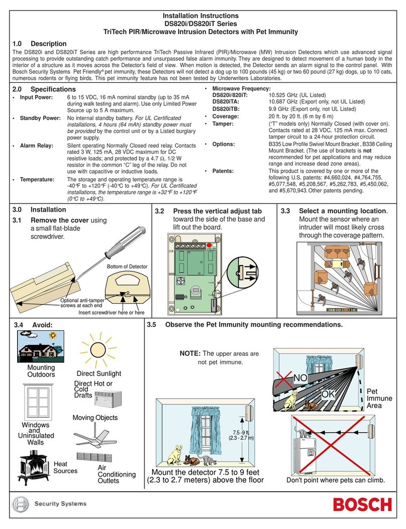
1 Wiringknockouts
2 Cabletie/strainrelief
3 Circuitboardsretainertabs
4 Bracketmountinghole
5 Mirrortracks
6 Cornermountingholes
7 Surfacemountingholes
8 Securingscrew
9 Tamperswitch
10 LED
11 Terminalblock
12 Circuitboard
Installation
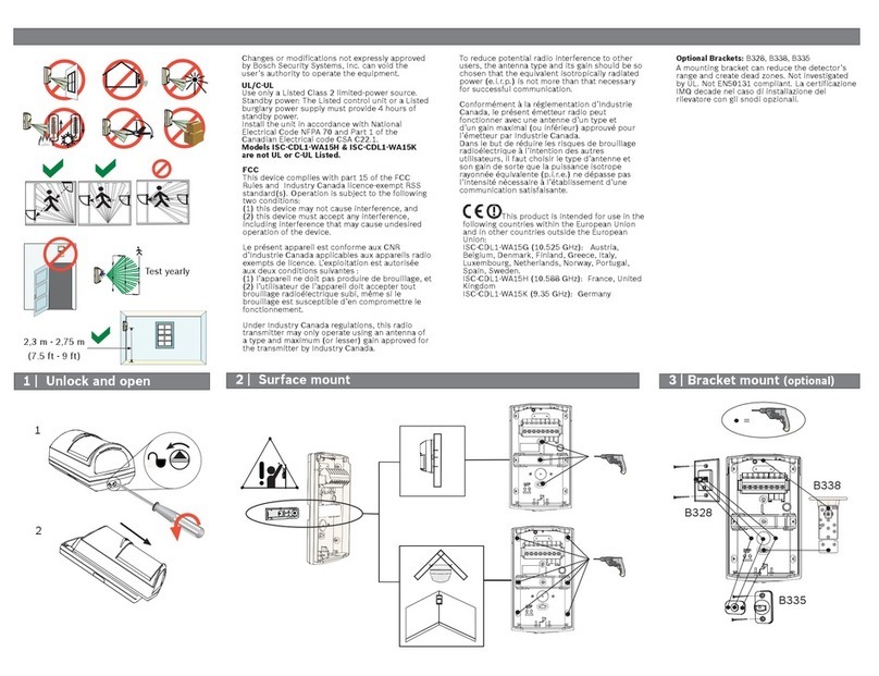
– Avoidthefollowinginsidethemonitoring
area:
– directhotorcolddraftsandaircondi-
tioningoutlets
– heatsources(aminimumdistanceof
1.5mtoaradiatorisnecessary)
– windows
– smallanimals
– directsunlight
– Thedetectorcannotdetectthroughglass.
– Whenusingtwoormoredetectors,thebest
coverageisachievedbyoverlappingthe
monitoringareas.Thedetectorsdonotaf-
fecteachother.
Installationpreparations
1. Selectasurfacethatissolidandfreeof
vibrations.Inordertoensuretheintru-
sionsecurityofdroppedceilings,detect-
orsshouldmonitoreachother.
Mounting
Notice!Removingmaskingfromthemirrorele-
mentsleavesadhesiveresiduethatpollutesthe
mirrorandleadstomalfunctionofthedetector.
VdSrequirementsprohibitmirrormasking.
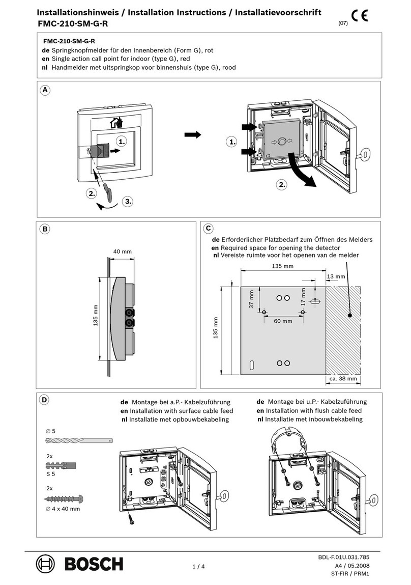
1. Toremovethecover,insertathinblade
screwdriverintothenotchatthebottomand
pryitopen.
2. Toremovethecircuitboard,pressoneof
thecircuitboardretainertabstowardsthe
sideoftheenclosureandliftthecircuit
boardoutoftheenclosurebase.
3. Slidethemirroroutofitstracks.
Notice!Toexchangethemirror,removethe
currentmirrorandslidetheothermirrorinto
thetracks.
4. Openanappropriatewiringknockoutbytap-
pingitwithascrewdriverthenroutethewir-
ingthroughtheopening.
5. Forstrainrelief,attachthecabletothe
cabletiewiththesuppliedplastictie-down.
Surfaceorcornermounting
1. Openeithertwoofthefoursurfacemount-
ingholesorthetwocornermountingholes.
2. Usetheenclosureasatemplateandmark
thelocationforthemountingscrews.
3. Firmlymountthedetectorwithappropriate
hardwaredependingonthemountingsur-
face(e.g.,anchors).
4. Insertthemirrorandcircuitboard.
Bracketmounting
Notice!Whenusingabracket,misalignmentof
thedetectormightreducethemonitoringrange.
1. Mountthebrackettothemountingsurface.
2. Knockoutthebracketmountingholeinthe
enclosurebaseandattachtheenclosureto
thebracket.
3. Insertthemirrorandcircuitboard.
Formoreinformationonthebracketmounting,
refertotheinstallationmanualofthebracket.
Selectingtheverticalangleofthemirror
1+2 aLSN1,bLSN1:comingfromthepreced-
ingLSNelement
3+4 aLSN2,bLSN:goingtothenextLSNele-
ment
5+6 Spareterminal
7 Connectionforgroundwirefromshiel-
dedcable
Forelement1–4:Useshieldedcableforbus
connections.
Notice!
Donotcoilexcesswireinsidetheen-
closureorsealthewireentrancewith
theplugprovided.
Configuration
1. Setthesensitivitytooneofthefollowing
settingsusingthesoftware:
Standardsensitivity(default)
– Protectionagainstfalsealarms
– Tolerancetoextremeenvironmentalcondi-
tions
– Notrecommendedforcurtainmirrorversion
Highsensitivity
– Recommendedsettingforanylocation
whereanintruderisexpectedtocoveronly
asmallportionofthemonitoringareaor
whenquickcatchperformanceisdesired
– Tolerancetonormalenvironmentalcondi-
tions
– Highresponsesensitivity
1| 2| 3| 4|
5| 6| 7| 8|
