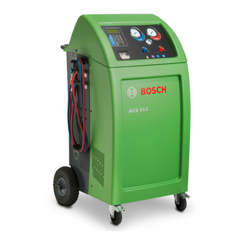
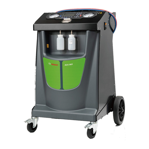
Bosch ACS 652 Setup guide

ACS 652
en
Repair instruction
A/C Service Unit

1 689 975 257 2019-05-15| Robert Bosch GmbH
2 | ACS 652 |en
en – Contents
1. Symbols used 3
1.1 In the documentation 3
1.1.1 Warning notices -
Structure and meaning 3
1.1.2 Symbols in this documentation 3
1.2 On the product 3
2. Important information 4
3. Test equipment and auxiliary materials 4
4. Safety regulations 5
4.1 Handling refrigerant R134a 5
4.2 Handling UV dye 5
4.3 Working on the vehicle 5
4.4 Notes on operation 6
4.5 Maintenance work 6
4.6 Safety devices 6
4.7 PED directive 2014/68/EU 6
5. Product description 7
5.1 Description of unit 7
5.1.1 Front view 7
5.1.2 Rear view 7
5.1.3 Display and control panel 8
5.1.4 Selection and function keys 8
5.1.5 Input keys 8
6. Program structure 9
6.1 Calibration and tare 9
6.2 Settings 9
6.3 Repair 9
6.4 Vehicle and customer data 9
6.5 Menu 9
6.6 Manual mode 9
6.7 Automatic mode 9
6.8 Flush (optional) 9
6.9 Enter 9
7. Hydraulics diagram 10
8. Service phases 11
8.1 Recovery 11
8.2 Draining oil into the used oil bottle 13
8.3 Vacuum phase and recycling
(simultaneous) 14
8.3.1 Vacuum phase 14
8.3.2 Recycle 14
8.4 Leak test 16
8.5 Refrigerant preparation 17
8.6 Fresh oil filling 18
8.7 UV contrast medium filling 19
8.8 Filling refrigerant 20
8.9 Separating and returning compressor oil 21
8.10 Non-condensing gases 22
9. Troubleshooting 23
9.1 Service messages 23
9.2 Fault messages 23
10. Emptying the ACS 652 24
10.1 Automatic emptying 24
10.2 Extraction of internal refrigerant circuit with sec-
ond A/C service unit 24
11. TROUBLESHOOTING AND ANALYSIS 25
11.1 Faults during recovery 25
11.1.1 Compressor starts 25
11.1.2 Compressor does not start 25
11.1.3 Fault messages that can occur during
recovery 26
11.1.4 Other fault messages 26
11.2 Faults during the vacuum phase 26
11.2.1 The vacuum pump starts 26
11.2.2 The vacuum pump does not start 26
11.2.3 Fault message that can occur during the
vacuum phase 27
11.3 Faults during refrigerant preparation 27
11.4 Non-condensing gases are not drained 27
11.5 Faults during filling with refrigerant 27
11.5.1 Vehicle air conditioning system cannot
be filled 27
11.5.2 Other fault messages 27
12. Component test and maintenance 28
12.1 Vacuum pump 28
12.2 Pressure sensor P1 28
12.3 Pressure switch P2 28
12.4 Expansion valve 28
12.5 Combo filter 29
12.5.1 Replacement of combo filter 29
12.5.2 Reset filter 29
12.6 Vacuum pump 30
12.6.1 Changing vacuum pump oil 30
12.6.2 Reset of oil change interval 30
13. Calibration 31
13.1 Internal refrigerant cylinder scales 31
13.2 Fresh oil bottle scales 31
13.4 Tara values 32
13.3 Used oil bottle scales 32
13.5 Pressure sensor 33
13.5.1 Checking the adjustment 33
13.5.2 Adjusting the pressure sensor 33

1 689 975 257 2019-05-15|Robert Bosch GmbH
Symbols used | ACS 652 | 3 en
14. Component test 34
14.1 LCD 34
14.2 Outputs 34
14.3 Control PCB input signal 34
14.4 Printer 34
14.5 Counter 35
14.6 Service printout 35
14.7 Draining oil 35
15. Changing basic settings 36
16. Software 37
16.1 Vehicle database 37
16.2 Data backup 37
16.3 Software update 37
16.4 Loading a data backup 37
17. Circuit diagram 38
17.1 Control PCB 38
17.2 Computer printed circuit board 39
1. Symbols used
1.1 In the documentation
1.1.1 Warning notices -
Structure and meaning
Warning notices warn of dangers to the user or people
in the vicinity. Warning notices also indicate the con-
sequences of the hazard as well as preventive action.
Warning notices have the following structure:
Warning
symbol KEY WORD – Nature and source of hazard!
Consequences of hazard in the event of fail-
ure to observe action and information given.
¶Hazard prevention action and information.
The key word indicates the likelihood of occurrence and
the severity of the hazard in the event of non-obser-
vance:
Key word Probability of
occurrence
Severity of danger if in-
structions not observed
DANGER Immediate impend-
ing danger
Death or severe injury
WARN-
ING
Possible impending
danger
Death or severe injury
CAUTION Possible dangerous
situation
Minor injury
1.1.2 Symbols in this documentation
Symbol Designation Explanation
!Attention Warns about possible property damage.
iInformation Practical hints and other
useful information.
1.
2.
Multi-step
operation
Instruction consisting of several steps.
eOne-step
operation
Instruction consisting of one step.
Intermediate
result
An instruction produces a visible inter-
mediate result.
"Final result There is a visible final result on com-
pletion of the instruction.
1.2 On the product
!Observe all warning notices on products and ensure
they remain legible.
¶Wear safety goggles.
¶Wear protective gloves.
¶Protect against dampness and moisture.

1 689 975 257 2019-05-15| Robert Bosch GmbH
4 | ACS 652 | Important informationen
2. Important information
Installation and/or repairs must only be performed by
trained and instructed Bosch customer service rep-
resentatives or companies authorized by Bosch If the
units are opened or modified by unauthorized persons,
any warranty claims become void.
Electrical systems and devices must only be put into
operation when in proper operating condition (details
can be found in the EDIS-Info 200108_084). This re-
quirement is met if following modification or repair (ini-
tial testing) it is ensured that the requirements of the
electrical engineering directives were adhered to. To
check this, tests should be performed, the nature and
extent of which are based on the measures specified in
the electrical engineering directives (e.g. in Germany
DGUV Vorschrift 3). The type and extent of the tests are
described in VDE 0701/0702 Part 1 within Germany.
The relevant national directives must be complied with.
3. Test equipment and auxil-
iary materials
RGeneral tools for electricians and A/C mechanics
RDigital multimeter (e.g. MMD 003)
RLoctite 542 (for thread seal) and 222 (for thread
lock)
RCleaning agent (e.g. brake cleaner)
RCalibrating weights 250 - 500 g for oil bottle scales
RCalibrating weight 10 - 20 kg for internal refrigerant
scale
RLeak detector (1 689 100 057)
RSimulator (optional)

1 689 975 257 2019-05-15|Robert Bosch GmbH
Safety regulations | ACS 652 | 5 en
4. Safety regulations
!Always carefully read and observe all the safety regu-
lations before using the Bosch product.
¶Wear safety goggles.
¶Wear safety gloves.
4.1 Handling refrigerant R134a
Avoid all skin contact with the refrigerant.
The low boiling point of the refrigerant (ap-
prox. -30 °C) can lead to frostbites. Should
it nevertheless come into contact with the
skin, remove any moistened clothing imme-
diately and rinse the affected skin with copi-
ous amounts of water.
RR134a is colorless, has a weak intrinsic odor and is
heavier than air. It displaces oxygen and may flow
into repair pits. Should refrigerant escape (malfunc-
tion), always ensure adequate ventilation and air
extraction (especially in pits). Exit the workshop.
Never inhale refrigerant and oil vapors. The
vapors can irritate the eyes, nose and respi-
ratory system. If liquid refrigerant comes
into contact with the eyes, rinse them thor-
oughly with water for 15 minutes. Then ob-
tain medical help even if no pain is felt.
RBefore connecting the ACS 652 to a vehicle air con-
ditioning system or an external refrigerant cylinder,
make sure the quick-release couplings are not leak-
ing.
ROnly ever use external refrigerant cylinders provided
with safety valves and certified in line with the ap-
plicable standards.
RBefore switching off the ACS 652, make sure all fill-
ing and drainage operations have been completed.
This prevents refrigerant escaping into the environ-
ment.
Do not use compressed air with R134a.
Some air mixtures with R134a are highly
flammable. Such mixtures are a potential
hazard and may lead to fire or explosions
and thus cause damage or injury.
RRefrigerant extracted from a vehicle air conditioning
system may be contaminated with moisture, lubri-
cant, dirt and traces of other gases.
RR134a is not to be used in areas in which there is a
danger of explosion. Fire, naked flames and smok-
ing are prohibited. Welding and soldering are not
permitted.
RHigh temperatures and UV radiation may chemically
separate the R134a. The resultant products cause
coughing and nausea.
RR134a is not to be mixed with other refrigerants.
The mixing of refrigerants can damage the vehicle air
conditioning system.
4.2 Handling UV dye
Never inhale UV dye. The vapors can irritate the
eyes, nose and respiratory system. If UV dye
comes into contact with the eyes, rinse them
thoroughly with water for 15 minutes. Then
obtain medical help even if no pain is felt.
RAvoid all skin contact with the UV dye. Should it nev-
ertheless come into contact with the skin, remove
any moistened clothing immediately and rinse the
affected skin with copious amounts of water.
RNever swallow UV dye. If swallowed inadvertently,
never attempt to induce vomiting. Drink copious
amounts of water and obtain medical help.
4.3 Working on the vehicle
If high-voltage components or high-voltage
wires are inexpertly handled, there is a risk of
fatal injury from high voltages and the possi-
ble transmission of current through the body.
RDe-energization is only to be performed by a quali-
fied electrician, a qualified electrician for specific
tasks (hybrid), or a power systems engineer.
RWork on vehicles with high-voltage components is
only ever to be performed in a safe, de-energized
condition by persons with the minimum qualification
"Trained to perform electrical work".
REven after deactivating the high-voltage vehicle
electrical system, the high-voltage battery may still
be live.
RThe operating condition cannot be established from
any running noise, as the electric machine is silent
when stationary.
RIn gear positions "P" and "N" the engine or electric
motor may start spontaneously depending on the
charge of the high-voltage battery.
RNever open or damage high-voltage batteries.
ROn accident vehicles, never touch high-voltage com-
ponents or exposed high-voltage wires before deacti-
vating the high-voltage vehicle electrical system

1 689 975 257 2019-05-15| Robert Bosch GmbH
6 | ACS 652 | Important informationen
4.4 Notes on operation
!Observe the pertinent legal regulations or directives
to ensure safe handling of pressurized devices.
RThe ACS 652 must be operated in an environment
corresponding to the directive BGR 157 with respect
to the exchange of air.
RObserve local laws or directives so as to ensure the
safety of the pressurized device. The ACS 652 must
be constantly monitored when in operation. Never
leave the ACS 652 unattended when in operation.
RPosition the ACS 652 on all four wheels on a flat,
vibration-proof surface such that proper operation of
the scales is guaranteed.
RThe ACS 652 can be secured in position by locking
the brake.
RThe ACS 652 must always be transported in its oper-
ating position. Never lay the ACS 652 on its side, as
oil could then escape from the vacuum pump, or the
built-in compressor could be damaged.
RThere are no additional safety systems for protecting
the ACS 652 against damage resulting from natural
catastrophes.
RACS 652 must be connected to a properly grounded
electrical connection.
RThe vehicle A/C service using the ACS 652 must be
prepared and implemented such that the vehicle
air conditioning system circuit does not have to be
opened (for example by removing the radiator or
engine).
RNever remove any components from inside the
ACS 652 except for maintenance or repair purposes.
RIf damage to the ACS 652 is established, terminate
usage immediately and contact customer service.
RThe service hoses and quick-release couplings must
be regularly checked for wear and replaced if dam-
aged.
4.5 Maintenance work
RNever perform any maintenance work which is not
expressly recommended in this manual. Contact
customer service if components have to be replaced
other than in the course of maintenance work.
RWe recommend calibrating the internal refrigerant
scales at least once per year. Please contact cus-
tomer service.
4.6 Safety devices
!For safety reasons it is advisable to use a residual
current operated circuit breaker (rccb) with the fol-
lowing specifications:
Parameters Specification
Rated voltage 230 VAC ± 10 %
Rated frequency 50/60 Hz
Rated current 230 VAC 10 A
Rated tripping current 30 mA
Tripping switch C
Overview of safety devices:
Description Operation
Pressure switch Switches the compressor off if the normal
operating pressure is exceeded.
Safety valve The safety valve opens if the design pres-
sure is exceeded.
Fuse Interrupts the power supply to ACS 652 in
the event of too high current.
Vents The ACS 652 is provided with vents in the
bottom of the housing to ensure the ex-
change of air even when switched off.
WARNING: Warranty is not valid in all
cases of improper use of the machine and
if the machine is not submitted to periodic
ordinary and extraordinary maintenance
(according to PED directive 2014/68/EU)
provided in this original instructions. The
manufacturer therefore declines all respon-
sibilities for any damage resulting from not
observing all the instructions and warnings
provided to the user regarding installation,
use and maintenance.
4.7 PED directive 2014/68/EU
The machine includes parts subject to PED EU directive
2014/68/EU, Pressure Equipment Directive. PED direc-
tive regulates all the pressurized part defining for them
categories based on volume-pressure ratio and based
on fluid refrigerant type. Those parts then have not to
be anyhow modified nor removed. Under the responsi-
bility of the owner, the machine and parts falling in the
scope of PED shall be checked either during commis-
sioning and periodically fulfilling local country regula-
tions and norms.
Parts in the scope of PED are:
RTank.
RPressure relieve valve.
RHigh pressure switch.
RRecovery group.
RPiping.
iCall Bosch service center to get technical specifica-
tions for each part listed.

1 689 975 257 2019-05-15|Robert Bosch GmbH
Product description | ACS 652 | 7 en
5. Product description
5.1 Description of unit
5.1.1 Front view
4
6
5
3
8
7
9
10
1
2
Fig. 1: Front view
1 Printer
2 Display and control panel
3 Gauge low pressure (LP)
4 Gauge high pressure (HP)
5 Pressure gauge of internal refrigerant cylinder
6 Fresh oil bottle (PAG or POE)
7 UV dye bottle
8 Used oil bottle
9 Cover
10 Front wheels with locking brake
iThe high (4) and low pressure (3) gages show the
current pressure during the air conditioning service
on the vehicle. The small gage (5) is used to check the
bottle pressure in the internal refrigerant cylinder.
5.1.2 Rear view
1
5
4
3
2
6
7
Fig. 2: Rear view
1 Service quick-release coupling (low pressure)
2 Service quick-release coupling (high pressure)
3 Service hose
4 Service hose mount
5 Rear wheels
6 Power cord (socket)
7 Master switch

1 689 975 257 2019-05-15| Robert Bosch GmbH
8 | ACS 652 | Product descriptionen
5.1.3 Display and control panel
The display and control panel of the operating unit con-
trol the menus and the service phases.
7
8
9
10
1
4
3
2
5
6
Fig. 3: Display and control panel
1 Flushing
2 Automatic service
3 Filling
4 Vacuum
5 Removal by suction
6 LCD display
7 Key panel
8 Vehicle database
9 PS2 interface 1)
10 Function light
1) For updating firmware/software or database
5.1.4 Selection and function keys
Keys Name Operation
Evacuation Refrigerant is extracted from the
vehicle.
RControl up
RVacuum
RUpward cursor movement.
RA vacuum is generated.
RControl
right
RFilling
RCursor movement to the right.
RVehicle air conditioning system
is filled with refrigerant.
RControl
left
RAutomatic
RCursor movement to the left.
RAutomatic service run: Air condi-
tioning service is carried out ac-
cording to saved parameters.
RControl
down
RFlushing
RDownward cursor movement.
RFlush components of the vehicle
air conditioning.
Menu
Call up various function for service
and data management.
Database
Call up databases:
RUSER SPECS
RVEHICLE DATAS
Enter (E)Confirm and take over.
Stop Terminate and return.
Various functions are assigned to the <MENU> function
key in the ACS 652 software. The functions of the keys
are defined in the menu line of the ACS 652 software.
5.1.5 Input keys
The input keys can be used to enter letters, numbers
and special characters in the input boxes.

1 689 975 257 2019-05-15|Robert Bosch GmbH
Program structure | ACS 652 | 9 en
6. Program structure
6.1 Calibration and tare
Input Menu
1. + <3>
2. Enter 1111.
3. Confirm with E.
TANK CALIBRATION
IN OIL CALIBRATION
OUT OIL CALIBRATION
PRES. CALIBRATION
TANK TARE
IN OIL TARE
OUT OIL TARE
6.2 Settings
Input Menu
1. + <3>
2. Enter 2222.
3. Confirm with E.
LANGUAGE
DATE/TIME
UNIT OF MEASURE
HOSES LENGTH
CONTRAST
GARAGE ADDRESS
FLUSHING
OIL SCALE
UV DYE
DATABASE UPDATE
SERIAL NUMBER
EXPERT MODE
6.3 Repair
Input Menu
1. + <3>
2. Enter 5555.
3. Confirm with E.
CHANGE FILTER
CHANGE OIL
6.4 Vehicle and customer data
Input Menu 1 Menu 2
<Database>
STANDARD SPECS EUROPEAN DATABASE
USER SPECS SELECT MODEL :
DELETE MODEL :
ADD MODEL :
VEHICLE DATAS
6.5 Menu
Input Menu 1 Menu 2
<Menu>
PERFORMANCE TESTS
DIAGNOSTIC
TANK FILLING
TANK RECYCLING
ZEROING OIL SCALES
REPORT MANAGEMENT PRINT REPORT
EXPORT DATA
DELETE DATA
6.6 Manual mode
Input Menu
<RECOVERY>
RAutomatic emptying
RExtraction
ROil drain
RPressure test
SELECT PORTS
...
Input Menu
<VACUUM>
SET VACUUM TIME
...
Input Menu
<CHARGE>
SELECT PORTS
...
6.7 Automatic mode
Input Menu
<AUTOMATIC>
SELECT PORTS
...
6.8 Flush (optional)
Input Menu
<FLUSH>
SET VACUUM TIME
...
6.9 Enter
Input Menu
<ENTER>
Information on current filling ca-
pacities of fresh and used oil bot-
tles and the internal refrigerant cyl-
inder

1 689 975 257 2019-05-15| Robert Bosch GmbH
10 | ACS 652 | Hydraulics diagramen
7. Hydraulics diagram
M2
P1
T1
T2
1
2
P
EV1
EV5
EV3
EV6
3F1
C
P2
HP
5
VU2
6
F2
9
4
EV7 10
7
V1
8
V3 V2V4
V6V5
M1
M3
13
12
11
EV10
VU3 VU1
EV8EV9
EVLP1 EVLP2
EVHP1 EVHP2
R1
R2
HOSE FLUSH MANIFOLD
SERVICE PORT
Name Description
1Fresh oil tank
2Vacuum pump
3Expansion valve
4Evaporator/oil separator
5Compressor oil separator
6Compressor
7Internal refrigerant cylinder
8Refrigerant cylinder scales
9Used oil bottle
10 Heat exchanger
11 UV dye bottle
12 Fresh oil scales
13 Used oil scales
EV1 Vacuum solenoid valve
EV3 Flow solenoid valve
EV5 Recovery solenoid valve
EV6 Filling solenoid valve
Name Description
EV7 Oil drain solenoid valve
EV8 Oil injection solenoid valve
EV9 Contrast medium injection sole-
noid valve
EV10 Solenoid valve for separating
high and low pressure
EVHP1 High pressure solenoid valve
EVHP2 High pressure solenoid valve
EVLP1 Low pressure solenoid valve
EVLP2 Low pressure solenoid valve
F1 Coarse filter
F2 Combi filter
HP High pressure
LP LOw pressure
M1 Low pressure gage
M2 High pressure gage
M3 Internal refrigerant cylinder pres-
sure gage
Name Description
P1 Pressure sensor
P2 Pressure switch
R1 Low pressure flushing connection
R2 High pressure flushing connection
T1 Low pressure hose
T2 High pressure hose
V1 Tank vapour side hose valve
V2 Tank liquid side hose valve
V3 Tank vapour side valve
V4 Tank liquid side valve
V5 Safety valve
V6 Non condensable drain valve
VU1 Oil non-return valve
VU2 One-way valve
VU3 UV contrast medium non-return
valve

1 689 975 257 2019-05-15|Robert Bosch GmbH
Service phases | ACS 652 | 11 en
8. Service phases
iThis section describes all of the ACS 652 service
phases. In addition, it explains the hydraulic and
electric circuits by presenting the hydraulic diagram
and providing a brief description of the components
involved in each function.
8.1 Recovery
iIn this service phase, the refrigerant is extracted
from the vehicle air conditioning system.
1. The ACS 652 is connected to the vehicle with the
service hoses T1 and T2.
2. Open the service quick-release coupling valves.
The pressure on the high and low pressure side of
the vehicle air conditioning system is indicated on
the pressure gages M1 and M2.
iBy selecting the LOW and HIGH ports (through the
software) EVHP1, EVHP2, EVLP1, EVLP2, EV10 sole-
noid valves are opened and the coolant reaches EV9
EV8, EV1, EV3 (normally closed) solenoid valves and
is in contact with the P1 pressure transducer.
iThe pressure sensor P1 checks the pressure of the
vehicle air conditioning system (whether or not there
is refrigerant in the vehicle air conditioning system).
3. starts extraction of the refrigerant.
The solenoid valves EV10, EV3 and EV5 are
opened and the compressor (6) is started.
RThe refrigerant flows through the solenoid valves
EVLP1, EVLP2, EVHP1, EVHP2, EV10, EV3 and EV5,
the mechanical filter (F1), the expansion valve (3),
and the condenser/separator (4).
RThe expansion valve (3) maintains a constant pres-
sure at the evaporator/oil separator (4).
RIn the evaporator/oil separator (4), the oil extracted
from the vehicle air conditioning system is separated
from the refrigerant and routed into the used oil
bottle (9).
RThe refrigerant then flows on through the combo fil-
ter (F2) and the compressor (6) into the condenser/
separator (5), and finally into the internal refrigerant
cylinder.
iThe combo filter (F2) cleans the extracted refriger-
ant of suspended particles and moisture.
iIn the evaporator/oil separator (5), the oil taken in
from the compressor is separated from the refriger-
ant and fed back to the compressor.
iIf the pressure at sensor P1 falls below the value
saved in the software, the function stops automati-
cally, the program waits 5 minutes for a pressure
increase and, if necessary, restarts with a second
recovery cycle.
At the end of this phase, the solenoid valves EVLP1,
EVLP2, EVHP1, EVHP2, EV10, EV3 and EV5 are closed
and the compressor 6 is turned off.

1 689 975 257 2019-05-15| Robert Bosch GmbH
12 | ACS 652 | Service phasesen
M2
P1
T1
T
2
EV5
EV3
EV6
3F1
C
P2
HP
5
VU2
6
F2
9
4
EV7 10
7
V1
8
V3 V2V4
V6V5
M1
M3
EV10
P
2
EV1
VU3
11
12
1
VU1
13
EV8EV9
EVLP1 EVLP2
EVHP1 EVHP2
R1
R2
HOSE FLUSH MANIFOLD
SERVICE PORT
Name Description
1Fresh oil tank
2Vacuum pump
3Expansion valve
4Evaporator/oil separator
5Compressor oil separator
6Compressor
7Internal refrigerant cylinder
8Refrigerant cylinder scales
9Used oil bottle
10 Heat exchanger
11 UV dye bottle
12 Fresh oil scales
13 Used oil scales
EV1 Vacuum solenoid valve
EV3 Flow solenoid valve
EV5 Recovery solenoid valve
EV6 Filling solenoid valve
Name Description
EV7 Oil drain solenoid valve
EV8 Oil injection solenoid valve
EV9 Contrast medium injection sole-
noid valve
EV10 Solenoid valve for separating
high and low pressure
EVHP1 High pressure solenoid valve
EVHP2 High pressure solenoid valve
EVLP1 Low pressure solenoid valve
EVLP2 Low pressure solenoid valve
F1 Coarse filter
F2 Combi filter
HP High pressure
LP LOw pressure
M1 Low pressure gage
M2 High pressure gage
M3 Internal refrigerant cylinder pres-
sure gage
Name Description
P1 Pressure sensor
P2 Pressure switch
R1 Low pressure flushing connection
R2 High pressure flushing connection
T1 Low pressure hose
T2 High pressure hose
V1 Tank vapour side hose valve
V2 Tank liquid side hose valve
V3 Tank vapour side valve
V4 Tank liquid side valve
V5 Safety valve
V6 Non condensable drain valve
VU1 Oil non-return valve
VU2 One-way valve
VU3 UV contrast medium non-return
valve

1 689 975 257 2019-05-15|Robert Bosch GmbH
Service phases | ACS 652 | 13 en
8.2 Draining oil into the used oil bottle
At the end of recovery, the solenoid valve EV7 opens
and the oil previously separated out in the evaporator/
oil separator (4) drains into the used oil bottle (9).
The used oil bottle scales (13) weigh the drained used
oil and ACS 652 saves the value for fresh oil filling in
automatic mode.
M2
P1
T1
T2
EV5
EV3
EV6
3F1
C
P2
HP
5
VU2
6
F2
9
4
EV7 10
7
V1
8
V3 V2V4
V6V5
M1
M3
EV10
P
2
EV1
13
EV9
11
VU3
EV8
12
VU1
1
EVLP1 EVLP2
EVHP1 EVHP2
R1
R2
HOSE FLUSH MANIFOLD
SERVICE PORT
Name Description
1Fresh oil tank
2Vacuum pump
3Expansion valve
4Evaporator/oil separator
5Compressor oil separator
6Compressor
7Internal refrigerant cylinder
8Refrigerant cylinder scales
9Used oil bottle
10 Heat exchanger
11 UV dye bottle
12 Fresh oil scales
13 Used oil scales
EV1 Vacuum solenoid valve
EV3 Flow solenoid valve
EV5 Recovery solenoid valve
EV6 Filling solenoid valve
Name Description
EV7 Oil drain solenoid valve
EV8 Oil injection solenoid valve
EV9 Contrast medium injection sole-
noid valve
EV10 Solenoid valve for separating
high and low pressure
EVHP1 High pressure solenoid valve
EVHP2 High pressure solenoid valve
EVLP1 Low pressure solenoid valve
EVLP2 Low pressure solenoid valve
F1 Coarse filter
F2 Combi filter
HP High pressure
LP LOw pressure
M1 Low pressure gage
M2 High pressure gage
M3 Internal refrigerant cylinder pres-
sure gage
Name Description
P1 Pressure sensor
P2 Pressure switch
R1 Low pressure flushing connection
R2 High pressure flushing connection
T1 Low pressure hose
T2 High pressure hose
V1 Tank vapour side hose valve
V2 Tank liquid side hose valve
V3 Tank vapour side valve
V4 Tank liquid side valve
V5 Safety valve
V6 Non condensable drain valve
VU1 Oil non-return valve
VU2 One-way valve
VU3 UV contrast medium non-return
valve

1 689 975 257 2019-05-15| Robert Bosch GmbH
14 | ACS 652 | Service phasesen
8.3 Vacuum phase and recycling
(simultaneous)
8.3.1 Vacuum phase
iDuring vacuum generation in the vehicle air condi-
tioning system, the refrigerant is prepared in the
internal refrigerant cylinder to remove the non-con-
densing gases before filling and to filter the refriger-
ant.
1. The ACS 652 is connected to the vehicle with the
service hoses T1 and T2.
2. Open the service quick-release coupling valves.
The pressure on the high and low pressure side of
the vehicle air conditioning system is indicated on
the pressure gages M1 and M2.
iBy selecting the LOW and HIGH ports (through the
software) EVHP1, EVHP2, EVLP1, EVLP2, EV10 so-
lenoid valves are opened and the A/C system starts
communication with P1 pressure transducer. P1
checks the pressure in the vehicle air conditioning
system (refrigerant present in the vehicle air condi-
tioning system or not).
iIf the pressure in the vehicle air conditioning system
is below the set value, the vehicle air conditioning
system is empty and the ACS 652 starts vacuum
generation.
iIf the pressure is above the set value, there is still re-
frigerant in the vehicle air conditioning system, and
it must be extracted before vacuum generation.
3. Press the <Vacuum> key.
EV1 and EV10 are opened and the vacuum pump
(2) starts.
iThe vacuum pump generates a maximum vacuum of
0.05 mbar. This depends on the duration of vacuum
generation.
iThe refrigerant in the internal refrigerant cylinder is
fed through the internal refrigerant circuit and pre-
pared in each vacuum phase.
8.3.2 Recycle
iDuring the vacuum function, the refrigerant recycle
starts automatically to further improve its purity
before the recharge.
iSome seconds after the vacuum stage has started,
the ecu excites the EV5 and EV6 solenoid valves by
opening them and starting compressor 6.
iIn that way, refrigerant is sucked from storage bottle
7 and is conveyed through the filter F1, the expan-
sion valve 3, the still/separator 4 until reaching the
tank again, as it happens in the recovery stage.
iThis function favours the automatic discharge of non
condensable gases inside the storage bottle.

1 689 975 257 2019-05-15|Robert Bosch GmbH
Service phases | ACS 652 | 15 en
M2
P1
T1
T
2
EV5
EV3
EV6
3F1
C
P2
HP
5
VU2
6
F2
9
4
EV7 10
7
V1
8
V3 V2V4
V6V5
M1
M3
EV10
P
2
EV1
13
EV8
12
VU1
1
EV9
11
VU3
EVLP1 EVLP2
EVHP1 EVHP2
R1
R2
HOSE FLUSH MANIFOLD
SERVICE PORT
Name Description
1Fresh oil tank
2Vacuum pump
3Expansion valve
4Evaporator/oil separator
5Compressor oil separator
6Compressor
7Internal refrigerant cylinder
8Refrigerant cylinder scales
9Used oil bottle
10 Heat exchanger
11 UV dye bottle
12 Fresh oil scales
13 Used oil scales
EV1 Vacuum solenoid valve
EV3 Flow solenoid valve
EV5 Recovery solenoid valve
EV6 Filling solenoid valve
Name Description
EV7 Oil drain solenoid valve
EV8 Oil injection solenoid valve
EV9 Contrast medium injection sole-
noid valve
EV10 Solenoid valve for separating
high and low pressure
EVHP1 High pressure solenoid valve
EVHP2 High pressure solenoid valve
EVLP1 Low pressure solenoid valve
EVLP2 Low pressure solenoid valve
F1 Coarse filter
F2 Combi filter
HP High pressure
LP LOw pressure
M1 Low pressure gage
M2 High pressure gage
M3 Internal refrigerant cylinder pres-
sure gage
Name Description
P1 Pressure sensor
P2 Pressure switch
R1 Low pressure flushing connection
R2 High pressure flushing connection
T1 Low pressure hose
T2 High pressure hose
V1 Tank vapour side hose valve
V2 Tank liquid side hose valve
V3 Tank vapour side valve
V4 Tank liquid side valve
V5 Safety valve
V6 Non condensable drain valve
VU1 Oil non-return valve
VU2 One-way valve
VU3 UV contrast medium non-return
valve

1 689 975 257 2019-05-15| Robert Bosch GmbH
16 | ACS 652 | Service phasesen
8.4 Leak test
iThe leak test starts after the vacuum phase.
iDuring this phase the EVHP1, EVHP2, EVLP1, EVLP2
and EV10 solenoid valves are open. After the speci-
fied vacuum time has elapsed, EV1 is closed to per-
form the leak test.
iIf the pressure at P 1 falls below the value saved in
the software during the leak test, an error message
is displayed.
M2
P1
T1
T2
EV5
EV3
EV6
3F1
C
P2
HP
5
VU2
6
F2
9
4
EV7 10
7
V1
8
V3 V2V4
V6V5
M1
M3
EV10
P
2
EV1
13
EV8
VU1
1
EV9
12
VU3
11
EVLP1 EVLP2
EVHP1 EVHP2
R1
R2
HOSE FLUSH MANIFOLD
SERVICE PORT
Name Description
1Fresh oil tank
2Vacuum pump
3Expansion valve
4Evaporator/oil separator
5Compressor oil separator
6Compressor
7Internal refrigerant cylinder
8Refrigerant cylinder scales
9Used oil bottle
10 Heat exchanger
11 UV dye bottle
12 Fresh oil scales
13 Used oil scales
EV1 Vacuum solenoid valve
EV3 Flow solenoid valve
EV5 Recovery solenoid valve
EV6 Filling solenoid valve
Name Description
EV7 Oil drain solenoid valve
EV8 Oil injection solenoid valve
EV9 Contrast medium injection sole-
noid valve
EV10 Solenoid valve for separating
high and low pressure
EVHP1 High pressure solenoid valve
EVHP2 High pressure solenoid valve
EVLP1 Low pressure solenoid valve
EVLP2 Low pressure solenoid valve
F1 Coarse filter
F2 Combi filter
HP High pressure
LP LOw pressure
M1 Low pressure gage
M2 High pressure gage
M3 Internal refrigerant cylinder pres-
sure gage
Name Description
P1 Pressure sensor
P2 Pressure switch
R1 Low pressure flushing connection
R2 High pressure flushing connection
T1 Low pressure hose
T2 High pressure hose
V1 Tank vapour side hose valve
V2 Tank liquid side hose valve
V3 Tank vapour side valve
V4 Tank liquid side valve
V5 Safety valve
V6 Non condensable drain valve
VU1 Oil non-return valve
VU2 One-way valve
VU3 UV contrast medium non-return
valve

1 689 975 257 2019-05-15|Robert Bosch GmbH
Service phases | ACS 652 | 17 en
8.5 Refrigerant preparation
1. Press the <MENU> key.
2. Select <R134a PREPARATION> and confirm with E.
"ACS 652 starts internal preparation of the refriger-
ant.
"EV5 and EV6 are opened and the compressor (6)
starts.
iInternal preparation of the refrigerant is the same
process that the ACS 652 performs in the recovery
phase to clean the refrigerant recovered from the
vehicle air conditioning system.
P1
EV5
EV3
EV6
3F1
C
P2
HP
5
VU2
6
F2
9
4
EV7 10
7
V1
8
V3 V2V4
V6V5
M3
EV10
P
2
EV1
11
VU3 VU1
12
1
EV8EV9
13
M2
T1
T
2
M1
EVLP1 EVLP2
EVHP1 EVHP2
R1
R2
HOSE FLUSH MANIFOLD
SERVICE PORT
Name Description
1Fresh oil tank
2Vacuum pump
3Expansion valve
4Evaporator/oil separator
5Compressor oil separator
6Compressor
7Internal refrigerant cylinder
8Refrigerant cylinder scales
9Used oil bottle
10 Heat exchanger
11 UV dye bottle
12 Fresh oil scales
13 Used oil scales
EV1 Vacuum solenoid valve
EV3 Flow solenoid valve
EV5 Recovery solenoid valve
EV6 Filling solenoid valve
Name Description
EV7 Oil drain solenoid valve
EV8 Oil injection solenoid valve
EV9 Contrast medium injection sole-
noid valve
EV10 Solenoid valve for separating
high and low pressure
EVHP1 High pressure solenoid valve
EVHP2 High pressure solenoid valve
EVLP1 Low pressure solenoid valve
EVLP2 Low pressure solenoid valve
F1 Coarse filter
F2 Combi filter
HP High pressure
LP LOw pressure
M1 Low pressure gage
M2 High pressure gage
M3 Internal refrigerant cylinder pres-
sure gage
Name Description
P1 Pressure sensor
P2 Pressure switch
R1 Low pressure flushing connection
R2 High pressure flushing connection
T1 Low pressure hose
T2 High pressure hose
V1 Tank vapour side hose valve
V2 Tank liquid side hose valve
V3 Tank vapour side valve
V4 Tank liquid side valve
V5 Safety valve
V6 Non condensable drain valve
VU1 Oil non-return valve
VU2 One-way valve
VU3 UV contrast medium non-return
valve

1 689 975 257 2019-05-15| Robert Bosch GmbH
18 | ACS 652 | Service phasesen
8.6 Fresh oil filling
iBy default, individual service phases are linked to
other service phases as they are needed to fully per-
form the individual operation selected.
iOil from the fresh oil bottle is used to top up the
vehicle air conditioning system compressor oil.
iIf "Fresh oil filling" has been selected in the service
process, the quantity of fresh oil entered is fed into
the vehicle air conditioning system along with the
refrigerant.
iThe filling quantity is checked by the scales (12),
which ends the filling process after the quantity pre-
viously entered in the service process.
iEV8 opens and the fresh oil (1) is fed into the vehicle
air conditioning system with the refrigerant.
P1
EV5
EV3
EV6
3F1
C
P2
HP
5
VU2
6
F2
9
4
EV7 10
7
V1
8
V3 V2V4
V6V5
M3
EV10
P
2
EV1
11
VU3 VU1
12
1
EV8EV9
13
M2
T1
T
2
M1
EVLP1 EVLP2
EVHP1 EVHP2
R1
R2
HOSE FLUSH MANIFOLD
SERVICE PORT
Name Description
1Fresh oil tank
2Vacuum pump
3Expansion valve
4Evaporator/oil separator
5Compressor oil separator
6Compressor
7Internal refrigerant cylinder
8Refrigerant cylinder scales
9Used oil bottle
10 Heat exchanger
11 UV dye bottle
12 Fresh oil scales
13 Used oil scales
EV1 Vacuum solenoid valve
EV3 Flow solenoid valve
EV5 Recovery solenoid valve
EV6 Filling solenoid valve
Name Description
EV7 Oil drain solenoid valve
EV8 Oil injection solenoid valve
EV9 Contrast medium injection sole-
noid valve
EV10 Solenoid valve for separating
high and low pressure
EVHP1 High pressure solenoid valve
EVHP2 High pressure solenoid valve
EVLP1 Low pressure solenoid valve
EVLP2 Low pressure solenoid valve
F1 Coarse filter
F2 Combi filter
HP High pressure
LP LOw pressure
M1 Low pressure gage
M2 High pressure gage
M3 Internal refrigerant cylinder pres-
sure gage
Name Description
P1 Pressure sensor
P2 Pressure switch
R1 Low pressure flushing connection
R2 High pressure flushing connection
T1 Low pressure hose
T2 High pressure hose
V1 Tank vapour side hose valve
V2 Tank liquid side hose valve
V3 Tank vapour side valve
V4 Tank liquid side valve
V5 Safety valve
V6 Non condensable drain valve
VU1 Oil non-return valve
VU2 One-way valve
VU3 UV contrast medium non-return
valve

1 689 975 257 2019-05-15|Robert Bosch GmbH
Service phases | ACS 652 | 19 en
8.7 UV contrast medium filling
iBy default, individual service phases are linked to
other service phases as they are needed to fully per-
form the individual operation selected.
iThe vehicle air conditioning system is partly filled
with UV contrast medium to facilitate detection of
leaks in the event of damage to the vehicle air condi-
tioning system.
iIf "UV contrast medium filling" has been selected in
the service process, a defined quantity (time con-
trolled) entered is fed into the vehicle air condition-
ing system along with the refrigerant.
iEVHP1, EVHP2 and EV9 opens and the UV contrast
medium (11) is fed into the vehicle air conditioning
system with the refrigerant.
M2
P1
T1
T
2
EV5
EV3
EV6
3F1
C
P2
HP
5
VU2
6
F2
9
4
EV7 10
7
V1
8
V3 V2V4
V6V5
M1
M3
EV10
P
2
EV1
11
VU3 VU1
12
1
EV8EV9
13
EVLP1 EVLP2
EVHP1 EVHP2
R1
R2
HOSE FLUSH MANIFOLD
SERVICE PORT
Name Description
1Fresh oil tank
2Vacuum pump
3Expansion valve
4Evaporator/oil separator
5Compressor oil separator
6Compressor
7Internal refrigerant cylinder
8Refrigerant cylinder scales
9Used oil bottle
10 Heat exchanger
11 UV dye bottle
12 Fresh oil scales
13 Used oil scales
EV1 Vacuum solenoid valve
EV3 Flow solenoid valve
EV5 Recovery solenoid valve
EV6 Filling solenoid valve
Name Description
EV7 Oil drain solenoid valve
EV8 Oil injection solenoid valve
EV9 Contrast medium injection sole-
noid valve
EV10 Solenoid valve for separating
high and low pressure
EVHP1 High pressure solenoid valve
EVHP2 High pressure solenoid valve
EVLP1 Low pressure solenoid valve
EVLP2 Low pressure solenoid valve
F1 Coarse filter
F2 Combi filter
HP High pressure
LP LOw pressure
M1 Low pressure gage
M2 High pressure gage
M3 Internal refrigerant cylinder pres-
sure gage
Name Description
P1 Pressure sensor
P2 Pressure switch
R1 Low pressure flushing connection
R2 High pressure flushing connection
T1 Low pressure hose
T2 High pressure hose
V1 Tank vapour side hose valve
V2 Tank liquid side hose valve
V3 Tank vapour side valve
V4 Tank liquid side valve
V5 Safety valve
V6 Non condensable drain valve
VU1 Oil non-return valve
VU2 One-way valve
VU3 UV contrast medium non-return
valve

1 689 975 257 2019-05-15| Robert Bosch GmbH
20 | ACS 652 | Service phasesen
8.8 Filling refrigerant
iThe refrigerant in the internal refrigerant cylinder is
used for filling the vehicle air conditioning system.
iRefrigerant can only be added to a vehicle air condi-
tioning system under a vacuum. The vacuum phase
must therefore be performed before filling.
iOpen EVHP1, EVHP2, EV 3 and EV 6.
Refrigerant flows from the internal refrigerant cylin-
der through valves V 4 and V 2, through the solenoid
valves EVHP1, EVHP2, EV3 and EV6
iThe filling quantity is checked by the scales (8),
which end the filling process after the quantity previ-
ously entered in the service process.
P1
EV5
EV3
EV6
3F1
C
P2
HP
5
VU2
6
F2
9
4
EV7 10
7
V1
8
V3 V2V4
V6V5
M3
EV10
P
2
EV1
11
VU3 VU1
12
1
EV8EV9
13
M2
T1
T
2
M1
EVLP1 EVLP2
EVHP1 EVHP2
R1
R2
HOSE FLUSH MANIFOLD
SERVICE PORT
Name Description
1Fresh oil tank
2Vacuum pump
3Expansion valve
4Evaporator/oil separator
5Compressor oil separator
6Compressor
7Internal refrigerant cylinder
8Refrigerant cylinder scales
9Used oil bottle
10 Heat exchanger
11 UV dye bottle
12 Fresh oil scales
13 Used oil scales
EV1 Vacuum solenoid valve
EV3 Flow solenoid valve
EV5 Recovery solenoid valve
EV6 Filling solenoid valve
Name Description
EV7 Oil drain solenoid valve
EV8 Oil injection solenoid valve
EV9 Contrast medium injection sole-
noid valve
EV10 Solenoid valve for separating
high and low pressure
EVHP1 High pressure solenoid valve
EVHP2 High pressure solenoid valve
EVLP1 Low pressure solenoid valve
EVLP2 Low pressure solenoid valve
F1 Coarse filter
F2 Combi filter
HP High pressure
LP LOw pressure
M1 Low pressure gage
M2 High pressure gage
M3 Internal refrigerant cylinder pres-
sure gage
Name Description
P1 Pressure sensor
P2 Pressure switch
R1 Low pressure flushing connection
R2 High pressure flushing connection
T1 Low pressure hose
T2 High pressure hose
V1 Tank vapour side hose valve
V2 Tank liquid side hose valve
V3 Tank vapour side valve
V4 Tank liquid side valve
V5 Safety valve
V6 Non condensable drain valve
VU1 Oil non-return valve
VU2 One-way valve
VU3 UV contrast medium non-return
valve
Table of contents
Other Bosch Service Equipment manuals

Bosch
Bosch ACS 651 User manual

Bosch
Bosch ACS 511 Setup guide

Bosch
Bosch TPA 300 User manual

Bosch
Bosch ACS 663 User manual

Bosch
Bosch T40075A User manual

Bosch
Bosch rexroth ctrlX SAFETY SafeMotion Instructions for use

Bosch
Bosch SCT 141 Series User manual

Bosch
Bosch ACS 600 User manual

Bosch
Bosch T10012 User manual

Bosch
Bosch DAS 3000 User manual

Bosch
Bosch CRR 130 User manual

Bosch
Bosch DAS 3000 Setup guide

Bosch
Bosch 1 687 010 398 User manual

Bosch
Bosch SCT 815 User manual

Bosch
Bosch ACS 810 Setup guide

Bosch
Bosch T10483 User manual

Bosch
Bosch 1 687 010 393 User manual

Bosch
Bosch ACS 251 User manual

Bosch
Bosch WBE 4200 Setup guide

Bosch
Bosch ACS 763 User manual