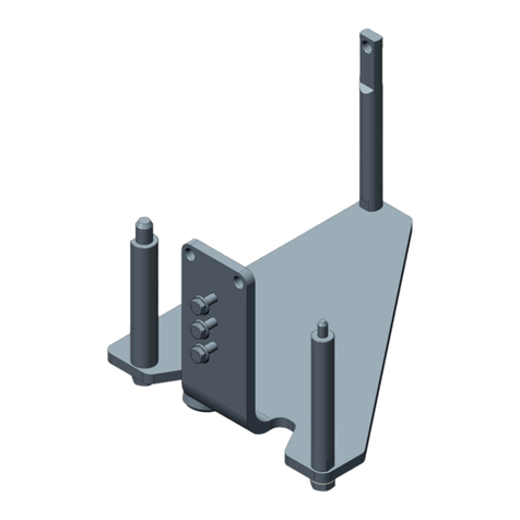
Bosch CRR 130 User manual

CRR 130
de
Originalbetriebsanleitung
Montagevorrichtung
en
Original instructions
Mounting device
fr
Notice orginale
Dispositif de montage
es
Manual original
Dispositivo de montaje
it
Istruzioni originali
Dispositivo di montaggio
sv
Bruksanvisning i original
Montagevorrichtung
nl
Oorspronkelijke gebruiksaanwijzing
Montage-inrichting
pt
Manual original
Dispositivo de montagem
fi
Alkuperäiset ohjeet
Asennuslaite
da
Original brugsanvisning
Monteringsanordningen
no
Original driftsinstruks
Montasjeinnretning
pl
Oryginalna instrukcja eksploatacji
Przyrząd montażowy
cs
Původní návod k používání
Montážní přípravek
tr
Orijinal işletme talimatı
Montagevorrichtung
zh
原始的指南
安装装置


0 986 629 130 2015-07-29|Robert Bosch GmbH
| 0 986 610 430 | 3 de
Inhaltsverzeichnis Deutsch 4
Contents English 9
Sommaire français 14
Índice español 19
Indice italiano 24
Innehållsförteckning svenska 29
Inhoud Nederlands 34
Contéudo português 39
Sisällysluettelo Suomi 44
Indholdsfortegnelse Dansk 49
Innholdsfortegnelse norsk 54
Spis treści po polsku 59
Obsah česky 64
İçindekiler Türkçe 69
目录中文 74

0 986 629 130 2015-07-29| Robert Bosch GmbH
4 | 0 986 610 430 | Verwendete Symbolikde
Inhaltsverzeichnis Deutsch
1. Verwendete Symbolik 4
1.1 In der Dokumentation 4
1.1.1 Warnhinweise – Aufbau und Bedeutung 4
1.1.2 Symbole – Benennung und Bedeutung 4
1.2 Auf dem Produkt 4
2. Produktbeschreibung 5
2.1 Bestimmungsgemäße Verwendung 5
2.2 Voraussetzungen 5
2.3 Schulungen 5
2.4 Lieferumfang 5
2.5 Sonderzubehör 5
2.6 Gerätebeschreibung 5
2.7 Funktionsbeschreibung 5
2.8 Sicherheitseinrichtungen 5
3. Erstinbetriebnahme 6
4. Bedienung 7
4.1 Anschlaghülse montieren und demontieren 7
4.2 Hinweise bei Störungen 7
5. Instandhaltung 8
5.1 Reinigung 8
5.2 Schlauchleitung prüfen 8
5.3 Ersatz- und Verschleißteile 8
6. Außerbetriebnahme 8
6.1 Ortswechsel 8
6.2 Entsorgung und Verschrottung 8
7. Technische Daten 8
7.1 Zulaufdruck und Temperatur 8
7.2 Maße und Gewichte 8
7.3 Geräuschemission 8
1. Verwendete Symbolik
1.1 In der Dokumentation
1.1.1 Warnhinweise – Aufbau und Bedeutung
Warnhinweise warnen vor Gefahren für den Benutzer oder
umstehende Personen. Zusätzlich beschreiben Warnhin-
weise die Folgen der Gefahr und die Maßnahmen zur Ver-
meidung. Warnhinweise haben folgenden Aufbau:
Warn-
symbol SIGNALWORT – Art und Quelle der Gefahr!
Folgen der Gefahr bei Missachtung der aufge-
führten Maßnahmen und Hinweise.
¶Maßnahmen und Hinweise zur Vermeidung
der Gefahr.
Das Signalwort zeigt die Eintrittswahrscheinlichkeit sowie
die Schwere der Gefahr bei Missachtung:
Signalwort Eintrittswahr-
scheinlichkeit
Schwere der Gefahr
bei Missachtung
GEFAHR Unmittelbar drohende
Gefahr
Tod oder schwere
Körperverletzung
WARNUNG Mögliche drohende
Gefahr
Tod oder schwere
Körperverletzung
VORSICHT Mögliche gefährliche
Situation
Leichte
Körperverletzung
1.1.2 Symbole – Benennung und Bedeutung
Symbol Benennung Bedeutung
!Achtung Warnt vor möglichen Sachschäden.
iInformation Anwendungshinweise und andere
nützliche Informationen.
1.
2.
Mehrschrittige
Handlung
Aus mehreren Schritten bestehende
Handlungsaufforderung.
eEinschrittige
Handlung
Aus einem Schritt bestehende
Handlungsaufforderung.
Zwischen-
ergebnis
Innerhalb einer Handlungsaufforderung
wird ein Zwischenergebnis sichtbar.
"Endergebnis Am Ende einer Handlungsaufforderung
wird das Endergebnis sichtbar.
1.2 Auf dem Produkt
!Alle Warnzeichen auf den Produkten beachten und in
lesbarem Zustand halten.

0 986 629 130 2015-07-29|Robert Bosch GmbH
Produktbeschreibung | 0 986 610 430 | 5 de
2. Produktbeschreibung
!Alle Sicherheitshinweise finden sie im Kapitel
Sicherheitshinweise in den Komponentenleitungen
für Bosch Injektoren (CR-Aystem) im Bosch-Informa-
tions-System ESI[tronic]. Diese sind vor Inbetrieb-
nahme, Anschluss und Bedienung von 0 986 610 430
sorgfältig durchzulesen und zwingend zu beachten.
2.1 Bestimmungsgemäße Verwendung
0 986 610 430 dient zur Demontage und Montage von
Anschlaghülsen einer Magnetbaugruppe des Bosch
Common-Rail-Injektors vom Typ CRI, CRIN mit Hilfe von
Stempeln und Aufnahmen.
!Für Fremd-Injektoren ist 0 986 610 430 nicht zugelas-
sen!
2.2 Voraussetzungen
RArbeitsplatz mit Traglast > 50 Kilogramm
RArbeitsplatte fest und verwindungssteif
RZur Befestigung beiliegende Schrauben oder
Schrauben mit mindestens Festigkeitsklasse 8.8
verwenden.
RBosch-Pneumatik-Steuergerät CRR 120
RBosch-Stempel und Aufnahmen (Sonderzubehör)
2.3 Schulungen
0 986 610 430 darf ausschließlich durch eingewiese-
nes, in der Dieselprüfung ausgebildetes Fachpersonal
bedient werden. Wir empfehlen eine Anwenderschulung
über das AA-Schulungszentrum in Prüfung und Instand-
setzung von Common Rail Injektoren (CRI/CRIN).
2.4 Lieferumfang
Benennung Bestellnummmer
Montagevorrichtung 0 986 610 430 0 986 610 430
Betriebsanleitung 0 986 629 130
2 x Innensechskantschraube M 10 x 80, 8.8 –
2 x Selbstsichernde Mutter M 10, 8.8 –
2 x Unterlagscheibe –
2.5 Sonderzubehör
Benennung / Verwendung Bestellnummmer
Stempel:
Einpressen CRI/CRIN- Hülse Magnetbaugruppe
Auspressen CRI- Hülse Magnetbaugruppe
Auspressen CRIN- Hülse Magnetbaugruppe
0 986 610 424
0 986 610 425
0 986 610 665
Aufnahme:
Auspressen CRI- Hülse Magnetbaugruppe
Einpressen CRI/CRIN -Hülse Magnetbaugruppe
Auspressen CRIN- Hülse Magnetbaugruppe
0 986 610 438
0 986 610 439
0 986 610 666
Steuergerät CRR 120 0 986 613 504
2.6 Gerätebeschreibung
Abb. 1: Montagevorrichtung 0 986 610 430
1 0 986 610 430 Montagevorrichtung
2 Taster
3 Pneumatik-Schlauchleitung
4 Wechselteile - Aufnahmen und Stempel (Sonderzubehör)
5 Befestigungsbohrungen
6 Eindrückstempel mit Schutzglocke
2.7 Funktionsbeschreibung
0 986 610 430 enthält einen pneumatischen Zylinder
zur Druckerzeugung auf den Eindrückstempel. Mit den
verschiedenen Aufnahmen und Stempeln (Sonderzube-
hör) wird die Demontage und Montage von Anschlag-
hülsen einer Magnetbaugruppe des Bosch Common-
Rail-Injektors vom Typ CRI oder CRIN vorgenommen.
2.8 Sicherheitseinrichtungen
Sicherheits-
einrichtung
Funktion
Definierter
Zulaufdruck
Die Druckluftversorgung des 0 986 610 430
muss an CRR 120 angeschlossen werden. Han-
delsübliche Pneumatikanschlüsse passen nicht
und dürfen nicht verwendet werden.
2-Hand-Be-
dienung
Freigabe des Tempels erfolgt durch eine 2-Hand-
Bedienung. Dadurch wird ausgeschlossen, dass
Finger gequetscht werden können. Vor Beginn
der Arbeit am 0 986 610 430 davon überzeugen,
dass sich keine weitere Person an der Montage-
vorrichtung befindet.
Schutzglocke
mit Kontroll-
ventil
Die Schutzglocke verhindert, dass Finger ge-
quetscht werden können. Das Kontrollventil
verhindert bei angehobener Schutzglocke die
Bewegung des Eindrückstempels. Die ordnungs-
gemäße Funktion der Schutzglocke und des Kon-
trollventils muss vor jedem Betrieb geprüft wer-
den.
Positionier-
hilfe
Magnetgruppe wird über eine Nut geführt und
muss senkrecht eingeschoben werden.

0 986 629 130 2015-07-29| Robert Bosch GmbH
6 | 0 986 610 430 | Erstinbetriebnahmede
3. Erstinbetriebnahme
!Die Montage des 0 986 610 430 darf nur von dafür
geschultem Personal vorgenommen werden.
!Die Schlauchleitung darf nicht geknickt oder auf Zug
beansprucht werden.
!Eine Verlängerung der Schlauchleitung oder die Be-
nutzung einer anderen Schlauchleitung ist unzulässig.
!Keinesfalls die Pneumatikschlauchleitung direkt an
das Druckluftsystem oder an ein anderes Pneumatik-
Steuergerät anschließen.
!Vor jedem Anschließen der Schlauchleitung an das
Pneumatik-Steuergerät CRR120 prüfen, ob der An-
schluss der Schlauchleitung sauber ist.
iWeitere Hinweise zur Bedienung finden Sie in der
Betriebsanleitung des CRR 120 und in den Kompo-
nentenleitungen für Bosch Injektoren (CR-System)
im Bosch-Informations-System ESI[tronic].
iDen Arbeitsplatz so auswählen, dass die Länge der
Schlauchleitung ausreicht, um das 0 986 610 430 an
das Pneumatik-Steuergerät CRR120 anzuschließen.
1. 0 986 610 430 auf Arbeitsplatte abstellen.
2. 0 986 610 430 mit Vorderansicht zum Benutzer
ausrichten, so dass das Einsetzen der Aufnahmen
(Fig.2,Pos.2) und die Bedienung über Taster von
vorn (Fig.2,Pos.1) möglich ist.
Abb. 2: Vorderansicht 0 986 610 430
1 Taster
2 Aufnahme in Führungsnut
3. 0 986 610 430 am Arbeitsplatz mit beiliegenden
Schrauben, Scheiben und Muttern befestigen.
4. CRR120 so auf Arbeitsplatte abstellen, dass
die Länge der Schlauchleitung ausreicht, um das
0 986 610 430 an das Pneumatik-Steuergerät
CRR120 anzuschließen.
Abb. 3: Pneumatik-Steuergerät CRR 120
1 Pneumatikanschluss A
5. CRR130 an den Pneumatikanschluss A (Fig.3,
Pos.1) des Pneumatik-Steuergerätes CRR120 an-
schließen.

0 986 629 130 2015-07-29|Robert Bosch GmbH
Bedienung | 0 986 610 430 | 7 de
4. Bedienung
WARNUNG - Quetschgefahr bei nicht bestim-
mungsgemäßer Verwendung!
Quetschgefahr bei geöffneter Schutzglocke
während des Pressvorgangs durch den Ein-
drückstempel.
¶Vergewissern Sie sich, dass das Kontroll-
ventil, das den Start bei angehobener
Schutzglocke verhindert, nicht blockiert ist.
¶Versichern Sie sich, dass während des
Pressvorgangs niemand an die Magnetbau-
gruppe mit Aufnahmen greifen kann.
¶Regelmäßige Kontrolle auf Beschädigungen
und Leckagen
4.1 Anschlaghülse montieren und demon-
tieren
iZusätzliche Sicherheitshinweise und Hinweise zur
Bedienung finden Sie in der Betriebsanleitung des
CRR120 und in den Komponentenleitungen für
Bosch-Injektoren (CR-System) im Bosch-Informa-
tions-System ESI[tronic]. Diese sind vor der Monta-
ge/Demontage zu lesen und zwingend zu beachten.
1. Schutzglocke (Fig. 4, Pos. 2) anheben.
Abb. 4: 0 986 610 430
1 Taster
2 Schutzglocke
3 Magnetbaugruppe mit den entsprechenden Stempeln und Auf-
nahmen
4 Aufnahme in Führungsnut
2. Magnetbaugruppe mit den entsprechenden Stem-
peln und Aufnahmen (Fig. 4, Pos. 3) bis zum An-
schlag in die Nut (Fig. 4, Pos. 4) des 0 986 610 430
schieben.
!Die Magnetbaugruppe muss senkrecht stehen!
3. Schutzglocke (Fig. 4, Pos. 2) absenken.
4. Kontrollieren. dass Pneumatikschlauchleitung an den
Anschluss A (Fig. 5, Pos. 5) von CRR120 angeschlos-
sen ist.
5. CRR120 durch Drehen des Hauptschalters
(Fig.5,Pos. 1) auf Stellung "1" einschalten.
Abb. 5: Pneumatik-Steuergerät CRR 120
1 Hauptschalter
2 Wechselschalter
3 Potentiometer
4 Ventil
5 Anschluss A für CRR 130
6. Wechselschalter (Fig. 5, Pos. 2) in Stellung P2 stel-
len.
7. Mit Potentiometer (Fig. 5, Pos. 3) am CRR120 den
benötigten Luftdruck gemäß den Anweisungen in den
Komponentenleitungen für Bosch-Injektoren (CR-Sys-
tem) im Bosch-Informations-System ESI[tronic] einstel-
len.
8. Ventil (Fig. 5, Pos. 4) betätigen.
Die eingestellte Druckluft wird zum CRR 130 ge-
leitet.
9. Beide Taster (Fig. 4, Pos. 1) gleichzeitig betätigen
und für etwa 5…8 Sekunden festhalten.
"Anschlaghülse montiert oder demontiert.
4.2 Hinweise bei Störungen
Bei Leckagen an Zylinder oder Schlauchleitung des
0 986 610 430 die Druckluftversorgung sofort am CRR
120
(Fig. 5, Pos.1) ausschalten.
iWeitere Hinweise finden Sie in der Betriebsanleitung
des CRR 120 und in den Komponentenleitungen für
Bosch-Injektoren (CR-System) im Bosch-Informa-
tions-System ESI[tronic].

0 986 629 130 2015-07-29| Robert Bosch GmbH
8 | 0 986 610 430 | Instandhaltungde
5. Instandhaltung
!Reinigungsarbeiten und Wartungsarbeiten dürfen
nur von geschultem Personal bei ausgesteckter
Schlauchleitung durchgeführt werden. Vor Beginn
der Arbeit am 0 986 610 430 davon überzeugen,
dass sich keine weitere Person an der Montagevor-
richtung befindet.
5.1 Reinigung
Die Führungsnut (Fig. 2, Pos. 2) täglich auf Schmutzp-
artikel kontrollieren. Die Schmutzpartikel mit einer Ab-
saugvorrichtung (0 986 613 111) entfernen.
5.2 Schlauchleitung prüfen
!Beschädigte Schlauchleitung und Kupplungsstecker
dürfen nicht repariert werden.
iDie Schlauchleitung immer sorgsam behandeln und
täglich vor Gebrauch überprüfen.
Die Schlauchleitung ist zu ersetzen, wenn bei der Über-
prüfung folgende Beschädigungen festgestellt werden:
RRisse, Versprödungen, Scheuerstellen am Schlauch-
mantel
RKnickstellen der Schlauchleitung.
RSchwergängige Kupplungsstecker der Schlauchlei-
tung.
RVerformter oder beschädigter Kupplungsstecker der
Schlauchleitung (Dichtkegel, Stecknippel, usw.).
5.3 Ersatz- und Verschleißteile
Benennung Bestellnummmer
Schlauchsatz 0 986 613 488
Anschlusssatz 0 986 613 491
6. Außerbetriebnahme
6.1 Ortswechsel
¶Bei Weitergabe von 0 986 610 430 die im Lieferumfang
vorhandene Dokumentation vollständig mit übergeben.
¶0 986 610 430 nur in Originalverpackung oder gleich-
wertiger Verpackung transportieren.

6.2 Entsorgung und Verschrottung
¶0 986 610 430 zerlegen, nach Material sortieren und
gemäß den geltenden Vorschriften entsorgen.
7. Technische Daten
7.1 Zulaufdruck und Temperatur
Funktion Spezifikation
Druckluft (nur über CRR 120 zulässig) 6…7 bar
Lagertemperatur -25 °C – 60 °C
Betriebstemperatur 0 °C – 40 °C
Umgebungstemperatur 10 °C
Maximal zulässige relative Luftfeuchte
(bei 25 °C und 24 Stunden Dauer)
≤90 %
7.2 Maße und Gewichte
Funktion Spezifikation
0 986 610 430 (H x B x T) 428 x 217 x 182 mm
0 986 610 430 (ohne Verpackung) 14,2 kg
7.3 Geräuschemission
Funktion Spezifikation
Schalldruckspegel bei 6 bar,
in 1 m Entfernung
75 dB(A)

0 986 629 130 2015-07-29|Robert Bosch GmbH
Symbols used | 0 986 610 430 | 9 en
Contents English
1. Symbols used 9
1.1 In the documentation 9
1.1.1 Warning notices - Structure and
meaning 9
1.1.2 Symbols in this documentation 9
1.2 On the product 9
2. Product description 10
2.1 Intended use 10
2.2 Prerequisites 10
2.3 Training 10
2.4 Scope of delivery 10
2.5 Special accessories 10
2.6 Description of unit 10
2.7 Functional description 10
2.8 Safety features 10
3. Initial commissioning 11
4. Operation 12
4.1 Assembly and disassembly of cable end
ferrules 12
4.2 Information in case of errors 12
5. Maintenance 13
5.1 Cleaning 13
5.2 Checking the hose 13
5.3 Replacement and wearing parts 13
6. Decommissioning 13
6.1 Change of location 13
6.2 Disposal and scrapping 13
7. Technical data 13
7.1 Supply pressure and temperature 13
7.2 Dimensions and weights 13
7.3 Noise emissions 13
1. Symbols used
1.1 In the documentation
1.1.1 Warning notices - Structure and meaning
Warning notices warn of dangers to the user or people
in the vicinity. Warning notices also indicate the con-
sequences of the hazard as well as preventive action.
Warning notices have the following structure:
Warning
symbol KEY WORD – Nature and source of hazard!
Consequences of hazard in the event of fail-
ure to observe action and information given.
¶Hazard prevention action and information.
The key word indicates the likelihood of occurrence and
the severity of the hazard in the event of non-obser-
vance:
Key word Probability of
occurrence
Severity of danger if in-
structions not observed
DANGER Immediate impend-
ing danger
Death or severe injury
WARNING Possible impending
danger
Death or severe injury
CAUTION Possible dangerous
situation
Minor injury
1.1.2 Symbols in this documentation
Symbol Designation Explanation
!Attention Warns about possible property damage.
iInformation Practical hints and other
useful information.
1.
2.
Multi-step
operation
Instruction consisting of several steps.
eOne-step
operation
Instruction consisting of one step.
Intermediate
result
An instruction produces a visible inter-
mediate result.
"Final result There is a visible final result on com-
pletion of the instruction.
1.2 On the product
!Observe all warning notices on products and ensure
they remain legible.

0 986 629 130 2015-07-29| Robert Bosch GmbH
10 | 0 986 610 430 | Product descriptionen
2. Product description
!All safety information can be found in the Safety
instructions chapter in the component instructions
for Bosch injectors (CR system) in the Bosch infor-
mation system ESI[tronic]. These instructions must
be carefully studied prior to start-up, connection and
operation of the 0 986 610 430 and must always be
heeded.
2.1 Intended use
The 0 986 610 430 is for disassembly and assembly of
cable end ferrules in a magnet assembly of the Bosch
common rail injector type CRI, CRIN using stamps and
mounts.
!The 0 986 610 430 is not licensed for third party
injectors!
2.2 Prerequisites
RWorkplace with load > 50 kilogram
RWorktop fixed and torsion-resistant
RFor attachment use supplied screws or screws with
minimum grade 8.8.
RBosch pneumatic control unit CRR 120
RBosch stamps and mounts (special accessories)
2.3 Training
The 0 986 610 430 must only be operated by specialist
personnel trained in diesel testing and instructed in its
use. We recommend user training through the AA train-
ing centre in testing and repair of common rail injectors
(CRI/CRIN).
2.4 Scope of delivery
Name Part number
Mounting device 0 986 610 430 0 986 610 430
Operating manual 0 986 629 130
2 x hexagon socket head bolt M 10 x 80, 8.8 –
2 x self-locking nut M 10, 8.8 –
2 x washer –
2.5 Special accessories
Name / use Part number
Stamp:
Pressing in CRI/CRIN ferrule magnet assembly
Pressing out CRI ferrule magnet assembly
Pressing out CRIN ferrule magnet assembly
0 986 610 424
0 986 610 425
0 986 610 665
Mount:
Pressing out CRI ferrule magnet assembly
Pressing in CRI/CRIN ferrule magnet assembly
Pressing out CRIN ferrule magnet assembly
0 986 610 438
0 986 610 439
0 986 610 666
Control unit CRR 120 0 986 613 504
2.6 Description of unit
Fig. 1: Mounting device 0 986 610 430
1 0 986 610 430 mounting device
2 Button
3 Pneumatic hose
4 Interchangeable parts – mounts and stamps
(special accessories)
5 Mounting holes
6 Push in stamp with protective cover
2.7 Functional description
The 0 986 610 430 includes a pneumatic cylinder for
applying pressure onto the push in stamp. With the
different mounts and stamps (special accessories),
cable end ferrules in a magnet assembly of the Bosch
common rail injector type CRI, CRIN are disassembled
or assembled.
2.8 Safety features
Safety fea-
ture
Function
Defined
supply
pressure
The compressed air supply of the 0 986 610 430
must be connected to CRR 120. Standard pneu-
matic connections do not fit and must not be
used.
2-hand
operation
The stamp is released through 2-hand operation.
This ensures that fingers will not be crushed.
Before starting work on the 0 986 610 430,
make sure
that no other person is in the vicinity of the
mounting device.
Protective
cover with
check valve
The protective cover ensures that fingers will
not be crushed. With the protective cover lifted,
the check valve stops the push in stamp from
moving. Proper functioning of the protective
cover and the check valve must be checked pri-
or to each operation.
Positioning
guide
The magnet assembly is guided across a groove
and must be inserted vertically.

0 986 629 130 2015-07-29|Robert Bosch GmbH
Initial commissioning | 0 986 610 430 | 11 en
3. Initial commissioning
!Only appropriately trained personnel is permitted to
assemble the 0 986 610 430.
!The hose must not be bent or overtensioned.
!It is not permitted to extend the hose or use another
one.
!The pneumatic hose must never be directly con-
nected to the compressed air system or to another
pneumatic control unit.
!Every time the hose is connected to the pneumatic
control unit CRR 120, first check whether the
connection of the hose is clean.
iMore information about operation can be found in
the operating manual of the CRR 120 and in the
component instructions for Bosch injectors (CR
system) in the Bosch information system ESI[tronic].
iChoose the workplace so that the length of the hose
is sufficient to connect the 0 986 610 430 with the
pneumatic control unit CRR 120.
1. Position the 0 986 610 430 on the worktop.
2. Position the front view of the 0 986 610 430 towards
the user, so that the mounts can be inserted
(fig. 2, pos. 2) and operation is possible via buttons
from the front (fig. 2, pos. 1).
Fig. 2: Front view of 0 986 610 430
1 Button
2 Mounting into guide groove
3. Attach the 0 986 610 430 to the workplace with sup-
plied screws, washers and nuts.
4. Position the CRR 120 on the worktop in such a way
that the length of the hose is sufficient to connect
the 0 986 610 430 with the pneumatic control unit
CRR 120.
Fig. 3: Pneumatic control unit CRR 120
1 Pneumatic connection A
5. Connect the 0 986 610 430 to the pneumatic con-
nection A (fig. 3, pos. 1) of the pneumatic control
unit CRR 120.

0 986 629 130 2015-07-29| Robert Bosch GmbH
12 | 0 986 610 430 | Operationen
4. Operation
WARNING – Risk of crushing in case of non-
intended use!
Risk of crushing with protective cover open
during the push in process of the push in
stamp.
¶Make sure that the check valve, which
prevents start-up with the protective cover
lifted, is not blocked.
¶Ensure that no-one can touch the magnet
assembly with mounts during the push in
process.
¶Regular checks for damage and leaks
4.1 Assembly and disassembly of cable
end ferrules
iAdditional safety information and notes on operation
can be found in the operating manual of the CRR 120
and in the component instructions for Bosch
injectors (CR system) in the Bosch information
system ESI[tronic]. These are to be read before
assembly/disassembly and are mandatory.
1. Lift the protective cover (fig. 4, pos. 2).
Fig. 4: 0 986 610 430
1 Button
2 Protective cover
3 magnet assembly with the respective stamps and mounts
4 Mounting into guide groove
2. Insert the magnet assembly with the respective
stamps and mounts (fig. 4, pos. 3) up to the stop
into the groove (fig. 4, pos. 4) of the 0 986 610 430.
!The magnet assembly must be in vertical position!
3. Lower the protective cover (fig. 4, pos. 2).
4. Make sure that the pneumatic hose is attached to
connection A (fig. 5, pos. 5) of the CRR 120.
5. Switch on the CRR 120 by turning the main switch
(fig. 5, pos. 1) to position "1".
Fig. 5: Pneumatic control unit CRR 120
1 Master switch
2 Toggle switch
3 Potentiometer
4 Valve
5 Connection A for 0 986 610 430
6. Put the toggle switch (fig. 5, pos. 2) into positionP2.
7. Adjust the required air pressure according to the
information in the component instructions for Bosch
injectors (CR system) in the Bosch information
system ESI[tronic] using the potentiometer
(fig. 5, pos. 3) on the CRR 120.
8. Actuate the valve (fig. 5, pos. 4).
The set compressed air is guided to the
0 986 610 430.
9. Actuate both buttons (fig. 4, pos. 1) at the same
time and hold them down for approx. 5...8 seconds.
"Cable end ferrule assembled or disassembled.
4.2 Information in case of errors
In case of leaks on the cylinder or hose of the
0 986 610 430, immediately switch off the compressed
air supply on the CRR 120 (fig. 5, pos. 1).
iMore information can be found in the operating
manual of the CRR 120 and in the component
instructions for Bosch injectors (CR system) in the
Bosch information system ESI[tronic].

0 986 629 130 2015-07-29|Robert Bosch GmbH
Maintenance | 0 986 610 430 | 13 en
5. Maintenance
!Cleaning and maintenance procedures must
only be performed by trained personnel with the
hose stretched out. Before starting work on the
0 986 610 430, make sure that no other person is in
the vicinity of the mounting device.
5.1 Cleaning
Check the guide groove (fig. 2, pos. 2) daily for dirt par-
ticles. Remove the dirt particles with an extractor
(0 986 613 111).
5.2 Checking the hose
!Damaged hoses and connection plugs must not be
repaired.
iAlways handle the hose with care and check it every
day before use.
The hose is to be replaced if checking reveals the
following signs of damage:
RCracks, brittle areas or abrasions on the hose jacket.
RBreaks in the hose.
RStiff connection plugs of the hose.
RDeformed or damaged connection plug of the hose
(sealing cone, plug-in nipple, etc.)
5.3 Replacement and wearing parts
Name Part number
Hose set 0 986 613 488
Connection set 0 986 613 491
6. Decommissioning
6.1 Change of location
¶If the 0 986 610 430 is passed on, all the documenta-
tion included in the scope of delivery must be handed
over together with the unit.
¶The 0 986 610 430 is only ever to be transported in
the original or equivalent packaging.
6.2 Disposal and scrapping
¶Dismantle the 0 986 610 430 and sort out and
dispose of the different materials in accordance with
the applicable regulations.
7. Technical data
7.1 Supply pressure and temperature
Function Specification
Compressed air (only permitted via CRR
120)
6…7 bar
Storage temperature -25 °C – 60 °C
Operating temperature 0 °C – 40 °C
Ambient temperature 10 °C
Maximum permitted relative humidity
(at 25 °C and 24 hours duration)
≤90 %
7.2 Dimensions and weights
Function Specification
0 986 610 430 (H x W x D) 428 x 217 x 182 mm
0 986 610 430 (without packaging) 14,2 kg
7.3 Noise emissions
Function Specification
Sound pressure level at 6 bar,
at 1 m distance
75 dB(A)

0 986 629 130 2015-07-29| Robert Bosch GmbH
14 | 0 986 610 430 | Symboles utilisésfr
Sommaire français
1. Symboles utilisés 14
1.1 Dans la documentation 14
1.1.1 Avertissements – Conception
etsignification 14
1.1.2 Symboles – désignation
etsignificationxxx 14
1.2 Sur le produit 14
2. Description du produit 15
2.1 Utilisation conforme 15
2.2 Conditions nécessaires 15
2.3 Formations 15
2.4 Scope of delivery 15
2.5 Accessoires spéciaux 15
2.6 Description de l'appareil 15
2.7 Description du fonctionnement 15
2.8 Dispositifs de sécurité 15
3. Première mise en service 16
4. Utilisation 17
4.1 Monter et démonter la douille de butée 17
4.2 Remarques en cas de défauts 17
5. Maintenance 18
5.1 Nettoyage 18
5.2 Contrôler le flexible 18
5.3 Pièces de rechange et d’usure 18
6. Mise hors service 18
6.1 Déplacement 18
6.2 Elimination et mise au rebut 18
7. Caractéristiques techniques 18
7.1 Pression d'alimentation et température 18
7.2 Dimensions et poids 18
7.3 Emissions sonores 18
1. Symboles utilisés
1.1 Dans la documentation
1.1.1 Avertissements – Conception etsignification
Les avertissements mettent en garde contre les dangers
pour l’utilisateur et les personnes présentes à proximité.
En outre, les avertissements décrivent les conséquences
du danger et les mesures préventives. La structure des
avertissements est la suivante :
Symbole
d’avertisse-
ment
MOT CLÉ - Nature et source du danger!
Conséquences du danger en cas de
non-observation des mesures et indica-
tions.
¶Mesures et indications pour la pré-
vention du danger.
Le mot clé indique la probabilité de survenue ainsi que
la gravité du danger en cas de non-observation :
Mot clé Probabilité
de survenue
Gravité du danger en
cas de non-observation
DANGER Danger direct Mort ou blessure
corporelle grave
AVERTISSEMENT Danger potentiel Mort ou blessure
corporelle grave
PRUDENCE Situation potentiel-
lement dangereuse
Blessure corporelle
légère
1.1.2 Symboles – désignation etsignificationxxx
Symbole Désignation Signification
!Attention Signale des dommages matériels
potentiels.
iInformation Consignes d'utilisation et autres
informations utiles.
1.
2.
Procédure à plu-
sieurs étapes
Instruction d'exécution d’une opé-
ration comportant plusieurs étapes.
eProcédure à une
étape
Instruction d'exécution d’une opé-
ration comportant une seule étape.
Résultat inter-
médiaire
Un résultat intermédiaire est vi-
sible au cours d’une procédure.
"Résultat final Le résultat final est présenté à la
fin de la procédure.
1.2 Sur le produit
!Observer tous les avertissements qui figurent sur les
produits et les maintenir lisibles.

0 986 629 130 2015-07-29|Robert Bosch GmbH
Description du produit | 0 986 610 430 | 15 fr
2. Description du produit
!Vous trouverez toutes les consignes de sécurité dans
le chapitre Consignes de sécurité du mode d'emploi
des composants pour injecteurs Bosch (système CR)
du système d'informations Bosch ESI[tronic]. Avant
la mise en service, le raccordement et l'utilisation du
0 986 610 430, lire et appliquer ces consignes avec
attention.
2.1 Utilisation conforme
Le 0 986 610 430 permet de démonter et de monter les
douilles de butée sur le groupe magnétique d'un injec-
teur Common Rail Bosch de type CRI, CRIN à l'aide de
poinçons et de porte-poinçons.
!Ne pas utiliser le 0 986 610 430 pour des injecteurs
d'une autre marque que Bosch !
2.2 Conditions nécessaires
RPoste de travail d'une capacité de charge > 50 kg
RPlan de travail robuste et résistant à la torsion
RPour la fixation, utiliser les vis fournies ou des vis
ayant une classe de résistance minimum de 8.8.
RUnité de contrôle pneumatique Bosch CRR 120
RPoinçons et porte-poinçons Bosch (accessoires
spéciaux)
2.3 Formations
Le 0 986 610 430 doit être utilisé exclusivement par
des personnes qualifiées ayant suivi une formation au
contrôle diesel. Nous recommandons le stage utilisa-
teur du centre de formation AA relatif au contrôle et à la
réparation des injecteurs Common Rail (CRI/CRIN).
2.4 Scope of delivery
Désignation Numéro
de commande
Dispositif de montage 0 986 610 430 0 986 610 430
Manuel d'utilisation 0 986 629 130
2 vis à six pans creux M 10 x 80, 8.8 –
2 écrous autofreinés M 10, 8.8 –
2 rondelles –
2.5 Accessoires spéciaux
Dénomination / utilisation Numéro
de commande
Poinçon :
Insertion douille CRI/CRIN groupe magnétique
Extraction douille CRI groupe magnétique
Extraction douille CRIN groupe magnétique
0 986 610 424
0 986 610 425
0 986 610 665
Porte-poinçon:
Extraction douille CRI groupe magnétique
Insertion douille CRI/CRIN groupe magnétique
Extraction douille CRIN groupe magnétique
0 986 610 438
0 986 610 439
0 986 610 666
Unité de contrôle CRR 120 0 986 613 504
2.6 Description de l'appareil
Fig. 1: Dispositif de montage 0 986 610 430
1 Dispositif de montage 0 986 610 430
2 Boutons
3 Flexible pneumatique
4 Pièces de rechange – poinçon et porte-poinçons Bosch
(accessoires spéciaux)
5 Perçages de fixation
6 Poinçon d'insertion avec cloche de protection
2.7 Description du fonctionnement
Le 0 986 610 430 comporte un vérin pneumatique pour
exercer une pression sur le poinçon d'insertion. Le dé-
montage et le montage des douilles de butée du groupe
magnétique de l'injecteur Common Rail Bosch de type
CRI ou CRIN s'effectuent à l'aide des différents porte-
poinçons et poinçons (accessoires spéciaux).
2.8 Dispositifs de sécurité
Dispositif de
sécurité
Fonction
Pression d'ali-
mentation dé-
finie
L'alimentation en air comprimé du
0 986 610 430 doit être raccordée au CRR 120.
Les connexions pneumatiques du commerce ne
sont pas adaptées et ne doivent pas être utili-
sées.
Commande à
2 mains
Le poinçon est libéré à l'aide d'une commande
à 2 mains. Cela évite tout risque d'écrasement
des doigts et des mains. Avant d'utiliser le
0 986 610 430,
s'assurer qu'aucune autre personne ne se
trouve à proximité du dispositif de montage.
Cloche de
protection
avec soupape
de contrôle
La cloche de protection sert à empêcher tout
risque d'écrasement des doigts de l'opérateur.
La soupape de contrôle empêche tout mouve-
ment du poinçon d'insertion lorsque la cloche
de protection est levée. S'assurer du bon fonc-
tionnement de la cloche de protection et de
la soupape de contrôle avant chaque utilisation.
Aide au posi-
tionnement
Le groupe magnétique est guidé au-dessus
d'une rainure et doit être introduit verticale-
ment.

0 986 629 130 2015-07-29| Robert Bosch GmbH
16 | 0 986 610 430 | Première mise en servicefr
3. Première mise en service
!Le montage du 0 986 610 430 doit être effectué uni-
quement par un personnel formé à cet effet.
!Ne pas plier ni soumettre le flexible à des contraintes
de traction.
!Ne pas rallonger le flexible et ne pas utiliser d'autre
flexible que celui qui a été fourni.
!Ne raccorder en aucun cas le flexible pneumatique
directement au système d'air comprimé ni à une
autre unité de contrôle pneumatique.
!Avant de raccorder le flexible à l'unité de contrôle
pneumatique CRR 120, vérifier si le raccord du
flexible est propre.
iVous trouverez de plus amples informations concer-
nant l'utilisation dans le manuel d'utilisation du CRR
120 et dans le mode d'emploi des composants pour
injecteurs Bosch (système CR) du système d'informa-
tions Bosch ESI[tronic].
iChoisir le poste de travail de sorte que la longueur
du flexible suffise pour raccorder le 0 986 610 430 à
l'unité de contrôle pneumatique CRR 120.
1. 0 986 610 430 sur le plan de travail.
2. Placer le 0 986 610 430 avec la vue avant face à l'uti-
lisateur de sorte qu'il puisse insérer les porte-poin-
çons (fig. 2, pos. 2) et commander l'appareil à l'aide
des boutons situés à l'avant (fig. 2, pos. 1).
Fig. 2: Vue avant du 0 986 610 430
1 Boutons
2 Porte-poinçon dans la rainure de guidage
3. Fixer le 0 986 610 430 sur le poste de travail à l'aide
des vis, des rondelles et des écrous fournis.
4. Placer le CRR 120 sur le plan de travail de sorte
que la longueur du flexible suffise pour raccorder
le 0 986 610 430 à l'unité de contrôle pneumatique
CRR 120.
Fig. 3: Unité de contrôle pneumatique CRR 120
1 Connexion pneumatique A
5. Raccorder le 0 986 610 430 à la connexion pneuma-
tique A (fig. 3, pos. 1) de l'unité de contrôle pneuma-
tique CRR 120.

0 986 629 130 2015-07-29|Robert Bosch GmbH
Utilisation | 0 986 610 430 | 17 fr
4. Utilisation
AVERTISSEMENT – Risque de pincement en
cas d'utilisation non conforme !
Risque de pincement lorsque la cloche de
protection est ouverte pendant le processus
de pression du poinçon d'insertion.
¶S'assurer que la soupape de contrôle, qui
empêche le démarrage lorsque la cloche de
protection est levée, n'est pas bloquée.
¶Pendant le processus de pression, s'assurer
que personne ne peut accéder au groupe
magnétique et aux porte-poinçons.
¶Contrôler régulièrement l'absence de dom-
mages et de fuites
4.1 Monter et démonter la douille de
butée
iVous trouverez des consignes de sécurité complémen-
taires et de plus amples informations concernant l'utili-
sation dans le manuel d'utilisation du CRR 120 et dans
le mode d'emploi des composants pour injecteurs
Bosch (système CR) du système d'informations Bosch
ESI[tronic]. Ces consignes doivent être lues et obser-
vées attentivement avant le montage/démontage.
1. Lever la cloche de protection (fig. 4, pos. 1).
Fig. 4: 0 986 610 430
1 Boutons
2 Cloche de protection
3 Glisser le groupe magnétique avec les poinçons et les porte-poin-
çons
4 Porte-poinçon dans la rainure de guidage
2. Glisser le groupe magnétique avec les poinçons et
les porte-poinçons correspondants (fig. 4, pos. 3)
jusqu'en butée dans la rainure (fig. 4, pos. 4) du
0 986 610 430.
!Le groupe magnétique doit être posé parfaitement à
la verticale !
3. Abaisser la cloche de protection (fig. 4, pos. 2).
4. Vérifier que le flexible pneumatique est bien raccor-
dé à la connexion A (fig. 4, pos. 5) du CRR 120.
5. Mettre le CRR 120 en marche en tournant l'interrup-
teur principal (fig. 5, pos. 5) sur la position "1".
Fig. 5: Unité de contrôle pneumatique CRR 120
1 Interrupteur principal
2 Interrupteur à bascule
3 Potentiomètre
4 Valve
5 Connexion A pour 0 986 610 430
6. Mettre l'interrupteur à bascule (fig. 5, pos. 2) dans
la position P2.
7. Avec le potentiomètre (fig. 5, pos. 3) du CRR 120,
régler la pression d'air requise conformément aux
instructions figurant dans le mode d'emploi des
composants pour injecteurs Bosch (système CR) du
système d'informations Bosch ESI[tronic].
8. Actionner la valve (fig. 5, pos. 4).
La pression d'air réglée est fournie au
0 986 610 430.
9. Appuyer simultanément sur les boutons (fig. 4,
pos. 1) et les maintenir enfoncés pendant environ
5…8 secondes.
"Douille de butée montée ou démontée.
4.2 Remarques en cas de défauts
En cas de fuites au niveau du vérin ou du flexible du
0 986 610 430, couper immédiatement l'alimentation
en air comprimé du CRR 120 (fig. 5, pos.1).
iVous trouverez de plus amples informations à ce su-
jet dans le manuel d'utilisation du CRR 120 et dans
le mode d'emploi des composants pour injecteurs
Bosch (système CR) du système d'informations
Bosch ESI[tronic].

0 986 629 130 2015-07-29| Robert Bosch GmbH
18 | 0 986 610 430 | Maintenancefr
5. Maintenance
!Les travaux de nettoyage et les travaux de mainte-
nance doivent être effectués uniquement par un per-
sonnel formé une fois le flexible débranché. Avant
de commencer les travaux sur le 0 986 610 430,
vérifier que personne d'autre ne travaille sur le dis-
positif de montage.
5.1 Nettoyage
Contrôler la rainure de guidage (fig. 2, pos. 2) tous les
jours pour vérifier l'absence de particules de saleté.
Retirer les particules de saleté avec un aspirateur
(0 986 613 111).
5.2 Contrôler le flexible
!Les raccords mâles et les flexibles détériorés ne
doivent pas être réparés.
iToujours manipuler le flexible avec précaution et le
contrôler chaque jour avant usage.
Le flexible doit être remplacé si les détériorations sui-
vantes sont constatées lors du contrôle :
RFissures, porosités, zones de frottement sur l'enve-
loppe du flexible
RMarques de pliage sur le flexible.
RRaccords mâles du flexible grippés.
RRaccords mâles du flexible déformés ou endomma-
gés (cône d'étanchéité, nipple enfichable, etc.).
5.3 Pièces de rechange et d’usure
Désignation Numéro de commande
Jeu de flexibles 0 986 613 488
Jeu de connexions 0 986 613 491
6. Mise hors service
6.1 Déplacement
¶En cas de cession du 0 986 610 430, joindre l’intégrali-
té de la documentation fournie.
¶Ne transporter le 0 986 610 430 que dans son em-
ballage d'origine ou un emballage équivalent.
6.2 Elimination et mise au rebut
¶Désassembler le 0 986 610 430 , trier les matériaux
et les éliminer en application de la réglementation en
vigueur.
7. Caractéristiques tech-
niques
7.1 Pression d'alimentation et tempéra-
ture
Fonction Spécification
Air comprimé (autorisé uniquement via
le CRR 120)
6…7 bar
Température de stockage -25 °C – 60 °C
Température de service 0 °C – 40 °C
Température ambiante 10 °C
Humidité relative de l'air maximale ad-
missible (à 25 °C et pendant 24 heures)
≤90 %
7.2 Dimensions et poids
Fonction Spécification
0 986 610 430 (H x L x P) 428 x 217 x 182 mm
0 986 610 430 (sans emballage) 14,2 kg
7.3 Emissions sonores
Fonction Spécification
Niveau sonore pour 6 bar, à 1 m de
distance
75 dB(A)

0 986 629 130 2015-07-29|Robert Bosch GmbH
Símbolos empleados | 0 986 610 430 | 19 es
Índice español
1. Símbolos empleados 19
1.1 En la documentación 19
1.1.1 Advertencias: estructura y significado 19
1.1.2 Símbolos en esta documentación 19
1.2 En el producto 19
2. Descripción del producto 20
2.1 Uso conforme al previsto 20
2.2 Requisitos 20
2.3 Cursos de formación 20
2.4 Volumen de suministro 20
2.5 Accesorios especiales 20
2.6 Descripción del equipo 20
2.7 Descripción del funcionamiento 20
2.8 Dispositivos de seguridad 21
3. Primera puesta en servicio 21
4. Manejo 22
4.1 Montar y desmontar el casquillo de tope 22
4.2 Instrucciones en caso de avería 22
5. Mantenimiento 23
5.1 Limpieza 23
5.2 Comprobar el tubo flexible 23
5.3 Piezas de recambio y desgaste 23
6. Puesta fuera de servicio 23
6.1 Cambio de ubicación 23
6.2 Eliminación y desguace 23
7. Datos técnicos 23
7.1 Presión de alimentación y temperatura 23
7.2 Dimensiones y pesos 23
7.3 Emisión de ruidos 23
1. Símbolos empleados
1.1 En la documentación
1.1.1 Advertencias: estructura y significado
Las indicaciones de advertencia advierten de peligros
para el usuario o las personas circundantes. Adicional-
mente, las indicaciones de advertencia describen las
consecuencias del peligro y las medidas para evitarlo. Las
indicaciones de advertencia tienen la siguiente estructura:
Símbolo de
advertencia PALABRA CLAVE – Tipo y fuente del peligro!
Consecuencias del peligro si no se tienen en
cuenta las medidas e indicaciones mostradas.
¶Medidas e indicaciones de prevención
del peligro.
La palabra clave indica la probabilidad de ocurrencia
del peligro, así como la gravedad del mismo en caso de
inobservancia:
Palabra clave Probabilidad de
ocurrencia
Peligro grave en caso de
pasarse por alto
PELIGRO Peligro inmediato Muerte o lesiones físicas
graves
ADVERTENCIA Peligro amena-
zante
Muerte o lesiones físicas
graves
ATENCIÓN Posible situación
peligrosa
Lesiones físicas leves
1.1.2 Símbolos en esta documentación
Sím-
bolo
Denominación Significado
!Atención Advierte de posibles daños materiales.
iInformación Indicaciones de la aplicación y otras
informaciones útiles
1.
2.
Acción de
varios pasos
Solicitud de acción compuesta
de varios pasos
eAcción de un
solo paso
Solicitud de acción compuesta de
un solo paso
Resultado
intermedio
Dentro de una solicitud de acción se
puede ver un resultado intermedio.
"Resultado final Al final de una solicitud de acción se
puede ver el resultado final.
1.2 En el producto
!Tenga en cuenta todas las indicaciones de adverten-
cia en los productos y manténgalas bien legibles.

0 986 629 130 2015-07-29| Robert Bosch GmbH
20 | 0 986 610 430 | Descripción del productoes
2. Descripción del producto
!Todas las indicaciones de seguridad se encuentran
en el capítulo "Indicaciones de seguridad" de las ins-
trucciones de componentes para inyectores Bosch
(sistema CR) en el sistema de información Bosch
ESI[tronic]. Es obligatorio prestarles atención y leer-
las cuidadosamente antes de la puesta en funciona-
miento, la conexión y el manejo del 0 986 610 430.
2.1 Uso conforme al previsto
0 986 610 430 sirve para el desmontaje y montaje de
casquillos de tope de un conjunto magnético del inyec-
tor Common-Rail de Bosch del tipo CRI, CRIN con ayu-
da de punzones y apoyos.
!¡El 0 986 610 430 no está autorizado para inyectores
ajenos!
2.2 Requisitos
RPuesto de trabajo con carga portante > 50 kg
REncimera de trabajo fija y resistente a la torsión
REmplear para la fijación los tornillos adjuntos o torni-
llos de la clase de resistencia 8.8 como mínimo.
RUnidad de control neumático Bosch CRR 120
RPunzones y apoyos Bosch (accesorios especiales)
2.3 Cursos de formación
0 986 610 430 debe ser manejado exclusivamente por
personal especializado con la formación necesaria para
realizar comprobaciones de sistemas diésel. Recomen-
damos que se impartan a los usuarios cursos de forma-
ción a través del centro de formación AA en materia de
comprobación y reparación de inyectores Common Rail
(CRI/CRIN).
2.4 Volumen de suministro
Denominación Número de pedido
Dispositivo de montaje 0 986 610 430 0 986 610 430
Instrucciones de servicio 0 986 629 130
2 x tornillos de hexágono interior
M 10 x 80, 8.8
–
2 x tuercas autoblocantes M 10, 8.8 –
2 x arandelas –
2.5 Accesorios especiales
Denominación/Utilización Número de pedido
Punzón:
Insertar a presión CRI/CRIN – Casquillo con-
junto magnético
Expulsar a presión CRI –
Casquillo conjunto magnético
Expulsar a presión CRIN –
Casquillo conjunto magnético
0 986 610 424
0 986 610 425
0 986 610 665
Apoyo:
Expulsar a presión CRI –
Casquillo conjunto magnético
Insertar a presión CRI/CRIN –
Casquillo conjunto magnético
Expulsar a presión CRIN –
Casquillo conjunto magnético
0 986 610 438
0 986 610 439
0 986 610 666
Unidad de control CRR 120 0 986 613 504
2.6 Descripción del equipo
Fig. 1: Dispositivo de montaje 0 986 610 430
1 Dispositivo de montaje 0 986 610 430
2 Pulsador
3 Tubo flexible neumático
4 Piezas intercambiables – apoyos y punzón (accesorios especiales)
5 Orificios de fijación
6 Punzón de inserción a presión con campana de protección
2.7 Descripción del funcionamiento
0 986 610 430 dispone de un cilindro neumático para
la generación de presión sobre el punzón de inserción a
presión. El desmontaje y montaje de casquillos de tope
de un conjunto magnético del inyector Common-Rail de
Bosch del tipo CRI o CRIN se realiza con ayuda de los
diferentes punzones y apoyos (accesorios especiales).
Table of contents
Languages:
Other Bosch Service Equipment manuals

Bosch
Bosch T10483 User manual

Bosch
Bosch DAS 3000 User manual

Bosch
Bosch ACS 763 User manual

Bosch
Bosch SCT 141 Series User manual

Bosch
Bosch SCT 815 User manual

Bosch
Bosch T40075A User manual

Bosch
Bosch ACS 600 User manual

Bosch
Bosch DAS 3000 Setup guide

Bosch
Bosch ACS 652 Setup guide

Bosch
Bosch ACS 251 User manual

Bosch
Bosch 1 687 010 393 User manual

Bosch
Bosch ACS 553 User manual

Bosch
Bosch rexroth ctrlX SAFETY SafeMotion Instructions for use

Bosch
Bosch WBE 4200 Setup guide

Bosch
Bosch ACS 511 Setup guide

Bosch
Bosch TPA 300 User manual

Bosch
Bosch ACS 810 Setup guide

Bosch
Bosch ACS 663 User manual

Bosch
Bosch ACS 651 User manual

Bosch
Bosch 1 687 010 398 User manual