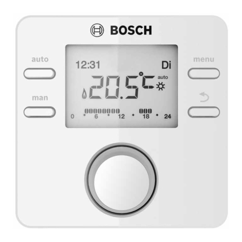
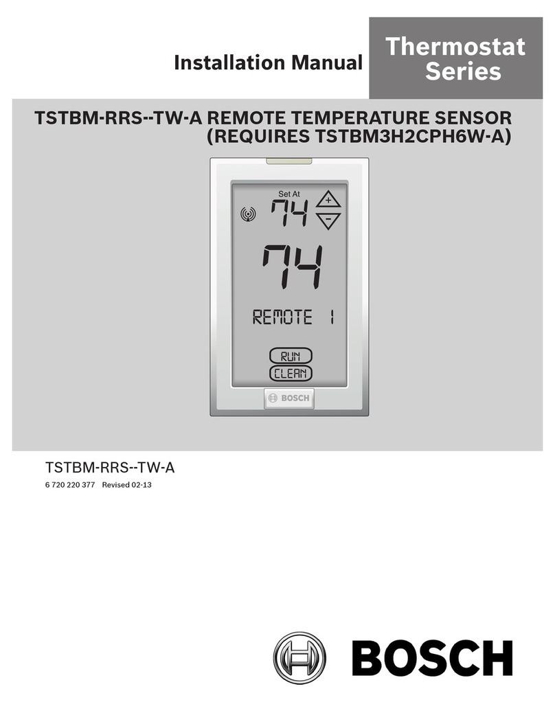
Bosch FR 10 User manual

110 | Contents
6 720 645 356 (2010/09)
Contents
1 Key to symbols and safety instructions . . . . . . . . . . . . 112
1.1 Key to symbols . . . . . . . . . . . . . . . . . . . . . . . . . . . 112
1.2 Safety instructions . . . . . . . . . . . . . . . . . . . . . . . . 114
2 Technical data for the accessory item . . . . . . . . . . . . . 115
2.1 Standard delivery . . . . . . . . . . . . . . . . . . . . . . . . . 115
2.2 Specification . . . . . . . . . . . . . . . . . . . . . . . . . . . . . 116
2.3 Supplementary accessories . . . . . . . . . . . . . . . . . 116
2.4 Cleaning . . . . . . . . . . . . . . . . . . . . . . . . . . . . . . . . 116
2.5 Sample system . . . . . . . . . . . . . . . . . . . . . . . . . . . 117
3 Installation (for contractors only) . . . . . . . . . . . . . . . . . 118
3.1 Installation . . . . . . . . . . . . . . . . . . . . . . . . . . . . . . 118
3.2 Disposal . . . . . . . . . . . . . . . . . . . . . . . . . . . . . . . . 119
3.3 Electrical connections . . . . . . . . . . . . . . . . . . . . . . 119
4 Commissioning (installers only) . . . . . . . . . . . . . . . . . . 121
5 Operation . . . . . . . . . . . . . . . . . . . . . . . . . . . . . . . . . . . . 122
5.1 Changing the operating mode . . . . . . . . . . . . . . . . 123
5.2 Changing the required room temperature . . . . . . 123
5.3 Changing the standard setting of the required
room temperature . . . . . . . . . . . . . . . . . . . . . . . . 124
5.4 Adjusting the contractor level (contractors only) . 126
5.5 Adjusting a heating program . . . . . . . . . . . . . . . . . 130
5.6 Frost protection . . . . . . . . . . . . . . . . . . . . . . . . . . 130
Appendix 159 | 111
6 720 645 356 (2010/09)
6 Troubleshooting . . . . . . . . . . . . . . . . . . . . . . . . . . . . . . 131
7 Energy saving tips . . . . . . . . . . . . . . . . . . . . . . . . . . . . . 134
8 Environmental protection . . . . . . . . . . . . . . . . . . . . . . . 136
Appendix . . . . . . . . . . . . . . . . . . . . . . . . . . . . . . . . . . . . 159

112 | Key to symbols and safety instructions
6 720 645 356 (2010/09)
1 Key to symbols and safety
instructions
1.1 Key to symbols
Warnings
Keywords at the start of a warning indicate the type and
seriousness of the ensuing risk if measures to prevent the risk are
not taken.
•NOTE indicates that material losses may occur.
•CAUTION indicates that minor to medium injury may occur.
•WARNING indicates that severe injury may occur.
•DANGER indicates a risk to life.
Warnings in this document are framed and
identified by a warning triangle printed against a
grey background.
If there is a danger due to electricity, the
exclamation mark in the warning triangle is
replaced by a lightning flash.

Key to symbols and safety instructions | 113
6 720 645 356 (2010/09)
Important information
Additional symbols
Important information where there is no risk to
people or property is indicated with the adjacent
symbol. It is bordered by lines above and below the
text.
Symbol Explanation
BAction
ÆCross-reference to other parts of this
document or to other documents
•List/list entry
–List/list entry (second level)
Table 6

114 | Key to symbols and safety instructions
6 720 645 356 (2010/09)
1.2 Safety instructions
BThese instructions must be observed to ensure correct
operation.
BInstall and commission the heating appliance and all
accessories in accordance with the instructions provided.
BAccessories must only be installed by suitably qualified
installers.
BOnly use these accessories in conjunction with the heating
appliances listed. Follow the connection diagram!
BNever connect this accessory to the 220 to 240 V mains.
BBefore installing this accessory:
Disconnect the power supply (220 to 240 V AC) to the heating
appliance and all other BUS subscribers.
BDo not install this accessory in damp areas.
BInstruct customers in the functions and operation of this
accessory.
BWhen there is a risk of frost, leave the heating appliance
switched on and follow the frost protection information.
Risk of damage due to operator error
Operator errors can result in injury and damage to property.
BEnsure that children never operate this appliance unsupervised
or play with it.
BEnsure that only personnel who can operate this appliance
correctly have access to it.

Technical data for the accessory item | 115
6 720 645 356 (2010/09)
2 Technical data for the accessory
item
•The FR 10 enables the room temperature control of a single
heating circuit.
•According to paragraph 12 of the EnEV (Order governing the
energy-saving thermal insulation and energy-saving system
technology in buildings in Germany), the FR 10 must only be
used in conjunction with a suitable time switch.
•In systems with a single heating circuit, you can change
automatically between the currently selected operating mode
/ / or heating operation blocked using the time
program of a time switch.
•The FR 10 can be used in systems with room temperature
controller FR 100/FR 110 to extend the system to up to 10
heating circuits (not permissible in Germany). For further
information, see the documentation of FR 100/FR 110.
•The controller is prepared for wall mounting.
2.1 Standard delivery
ÆFig. 2 on page 159:
1Top section, controller and wall mounting base
2Installation and operating instructions
The FR 10 can only be connected to a heating
appliance with BUS-enabled Heatronic 3.

116 | Technical data for the accessory item
6 720 645 356 (2010/09)
2.2 Specification
2.3 Supplementary accessories
See also the pricelist.
•MT 10: Analogue 1-channel time switch.
•DT 10: Digital 1-channel time switch.
•IPM 1: Module for controlling one mixed or one non-mixed
heating circuit.
2.4 Cleaning
BIf necessary, use a damp cloth to wipe the controller casing.
Never use aggressive or corrosive cleaning agents for this.
Dimensions Fig. 3, Page 160
Rated voltage 10 ... 24 V DC
Rated current ≤3.5 mA
Controller output 2-wire BUS
Control range 5 ... 30 °C in steps of 0.5 K
permiss. ambient temperature 0 ... +50 °C
Protection class III
IP rating IP20
Table 1

Technical data for the accessory item | 117
6 720 645 356 (2010/09)
2.5 Sample system
Sample systems for systems with several heating circuits (not
permissible in Germany) are contained in the documentation of
the room temperature controller FR 100/FR 110.

118 | Installation (for contractors only)
6 720 645 356 (2010/09)
3 Installation (for contractors
only)
3.1 Installation
The quality of control of the FR 10 is influenced by the installation
location.
The installation location (= lead room) must be suitable for
controlling the heating system or heating circuit.
BSelect installation location (ÆFig. 3 on page 161).
BRemove top section from base. (ÆFig. 4 on page 161).
BFit the base (ÆFig. 5 on page 161).
BMake electrical connections (ÆFig. 6 on page 162).
BPush on top section.
DANGER: Risk of electric shock!
BBefore installing this accessory:
Disconnect the power supply (220 to 240 V AC)
to the heating appliance and all other BUS
subscribers.
The mounting surface on the wall should be level.

Installation (for contractors only) | 119
6 720 645 356 (2010/09)
3.2 Disposal
BDispose of packaging in an environmentally responsible
manner.
BWhen replacing components, dispose of the old components in
an environmentally responsible manner.
3.3 Electrical connections
BBUS connection from controller to other BUS subscribers:
Use cables that comply with local regulations and guidelines.
Permissible cable lengths from the BUS-enabled Heatronic 3 to
the controller:
BRoute all LV leads separately from cables carrying 220 to 240 V
or 380 to 415 V to avoid inductive interference (minimum
separation 100 mm).
BIn case of external inductive interference, shield the cables.
This ensures that the cables are shielded from external
interference (e.g. heavy current cables, overhead wires,
transformer stations, radio and television set, amateur radio
stations, microwave ovens etc).
Cable length Cross-section
≤80 m 0.40 mm2
≤100 m 0.50 mm2
≤150 m 0.75 mm2
≤200 m 1.00 mm2
≤300 m 1.50 mm2
Table 2

Commissioning (installers only) | 121
6 720 645 356 (2010/09)
4 Commissioning (installers only)
BSet the DIP switch on IPM 1 in accordance with the details in
the instructions supplied.
BSwitch on the system.
During first commissioning or after a global reset (resetting all
adjustments):
BFor systems with one heating circuit:
Acknowledge flashing code 1 HC by pressing .
-or-
BIf the controller is to regulate a heating circuit HC2...10 (not
permissible in Germany):
Select corresponding code 2 HC to 10 HC by turning and
confirm by pressing .
System configuration starts automatically, and after approx. 60
seconds AC will be displayed.
Only one FR 10 can be assigned per heating circuit
and per code.

122 | Operation
6 720 645 356 (2010/09)
5 Operation
The FR 10 can only regulate the heating system if an operating
mode is enabled. In conjunction with a time switch (accessory),
the time program automatically changes between the currently
selected operating mode / / and heating operation
blocked . Frost protection is ensured (ÆChapter 5.6 page 154).
Controls (ÆFig. 1 on page 159)
1Rotary selector :
- Turn = Adjust value
- Press = Confirm setting/value
2Modekey:
- Change operating mode
- Accessing user level = hold down for approx 3 seconds
- Accessing contractor level = Hold down for approx 6
seconds
- Return to the higher level
Symbols (ÆFig. 1 on page 159)
Current room temperature or required room
temperature(if the rotary selector is turned)
Operating mode High
Operating mode Low
Operating mode Frost
No heating operation available, e.g. heating mode
blocked due to time switch (accessory)
Burner operation
Table 3
Set the flow temperature controller at the boiler to
the maximum required flow temperature.

Operation | 123
6 720 645 356 (2010/09)
5.1 Changing the operating mode
BBriefly press mode until the required operating mode is
displayed.
= constant High
= constant Low
= constant Frost
The set operating mode is only active if heating operation is not
blocked .
5.2 Changing the required room temperature
BWith rotary selector adjust the required room
temperature for the current operating mode / / .
During this period, the required room temperature will flash
instead of the display showing the current room temperature.
The change to the required room temperature will remain in
force until the next operating mode change or until the power
is interrupted. At that point the system reverts to the room
temperature programmed at the user level for that particular
operating mode.
Use this function if you want to change the required
room temperature by way of an exception, e.g. for
the duration of a party.

124 | Operation
6 720 645 356 (2010/09)
5.3 Changing the standard setting of the required
room temperature
BAccessing user level: Hold down mode for approx. 3 seconds
until – – is displayed.
BRelease the mode key and turn until the required
parameter is shown:
–1A p = Required room temperature for High
–1b p = Required room temperature for Low
–1C p = Required room temperature for Frost
BBriefly press : The current temperature for the previously
selected parameter will be displayed.
BBriefly press : The current temperature flashes.
BTurn to adjust the required room temperature:
–High = maximum temperature required (e.g. if people are
spending time in the living areas and require a comfortable
temperature). Setting range is higher than Low up to
30 °C.
–Low = average temperature required (e.g. if a lower room
temperature is sufficient or if everyone is out or asleep and
the building must not cool down too much). Setting range
is higher than Frost and lower than High.
Use this function if you want to permanently change
the required room temperature away from the
standard setting.

Operation | 125
6 720 645 356 (2010/09)
–Frost = minimum required temperature (e.g. if everyone
is away or asleep and the house should not cool down
excessively). Consider any pets and plants. Setting range is
lower than Low down to a minimum of 5 °C.
BBriefly press to save the value.
BPress mode until the current room temperature is displayed.

126 | Operation
6 720 645 356 (2010/09)
5.4 Adjusting the contractor level (contractors
only)
BAccessing contractor level: Hold down mode for approx. 6
seconds until – – – is displayed.
BRelease the mode key and turn until the required
parameter is shown:
–5A p = Code
–5b p = Heating circuit configuration
–6A p = Calibrate the integral room temperature sensor
–6b p = Calibration factor I
–6C p = Amplification factor V
–6d p = Maximum flow temperature
–6E p = Mixer runtime
BBriefly press : The current value for the previously
selected parameter is displayed.
BBriefly press : The current value flashes.
BTurn to select the required value.
BBriefly press to save the value.
BPress mode until the current room temperature is displayed.
The contractor level is the exclusive domain of
contractors.

Operation | 127
6 720 645 356 (2010/09)
5.4.1 Changing the code (parameter: 5A p)
Setting range: 1to 10
Use this parameter if you want to adjust the code after
commissioning:
BFor systems with a single heating circuit: Select code 1.
-or-
BIf the controller is to regulate a heating circuit HK2...10 (not
permissible in Germany):
Set the corresponding code 2to 10.
5.4.2 Changing the heating circuit configuration (parameter:
5b p)
Setting range: 1to 3
Use this parameter if you want to alter the configuration after
commissioning:
BAdjusting the corresponding configuration:
–1= unmixed heating circuit without IPM
–2= unmixed heating circuit with IPM
–3= mixed heating circuit
Only one FR 10 can be assigned per heating circuit
and per code.

128 | Operation
6 720 645 356 (2010/09)
5.4.3 Calibrating the room temperature sensor (parameter: 6A p)
Setting range: – 3.0 °C (K) to +3.0 °C (K)
Use this parameter if you want to correct the displayed room
temperature.
BPosition a precision instrument near FR 10. The precision
instrument must not transfer any heat to the FR 10.
BKeep away heat sources such as sunlight, body heat, etc. for 1
hour.
BCalibrate the displayed room temperature correction value.
5.4.4 Selecting calibration factor I (parameter: 6b p)
Setting range: 0 % to 100 %
Calibration factor I represents the speed with which the constant
control deviation of the room temperature is compensated.
BSelecting calibration factor I:
–≤40 %: Set a lower factor to achieve minimal room
temperature overshoot by more gradual correction.
–≥40 %: Set a higher factor to achieve faster correction by
a greater room temperature overshoot.
Other manuals for FR 10
2
Table of contents
Other Bosch Thermostat manuals

Bosch
Bosch CT 100 User manual

Bosch
Bosch TRZ 12-2 User manual

Bosch
Bosch MT 10 User manual

Bosch
Bosch Smart Home Thermostat AA User manual

Bosch
Bosch BMS-WT1 Series User manual

Bosch
Bosch BCC50 User manual

Bosch
Bosch EasyControl User manual

Bosch
Bosch FR 10 User manual

Bosch
Bosch Climate 5000 Series User manual

Bosch
Bosch FR 10 Assembly Instructions

Bosch
Bosch TR 200 User manual

Bosch
Bosch TRZ 12-2 User manual

Bosch
Bosch BCC50 Assembly instructions

Bosch
Bosch CR 50 User manual

Bosch
Bosch Worcester Easy control User manual

Bosch
Bosch TSTBM-RRS--TW-A User manual

Bosch
Bosch 8-733-944-325 Guide

Bosch
Bosch DT1 User manual

Bosch
Bosch 3H/2C Guide

Bosch
Bosch CR 11 User manual