10 | English
– It is advisable to wear a P2 filter class breathing mask.
The regulations on the material being machined that apply in
the country of use must be observed.
uAvoid dust accumulation at the workplace. Dust can
easily ignite.
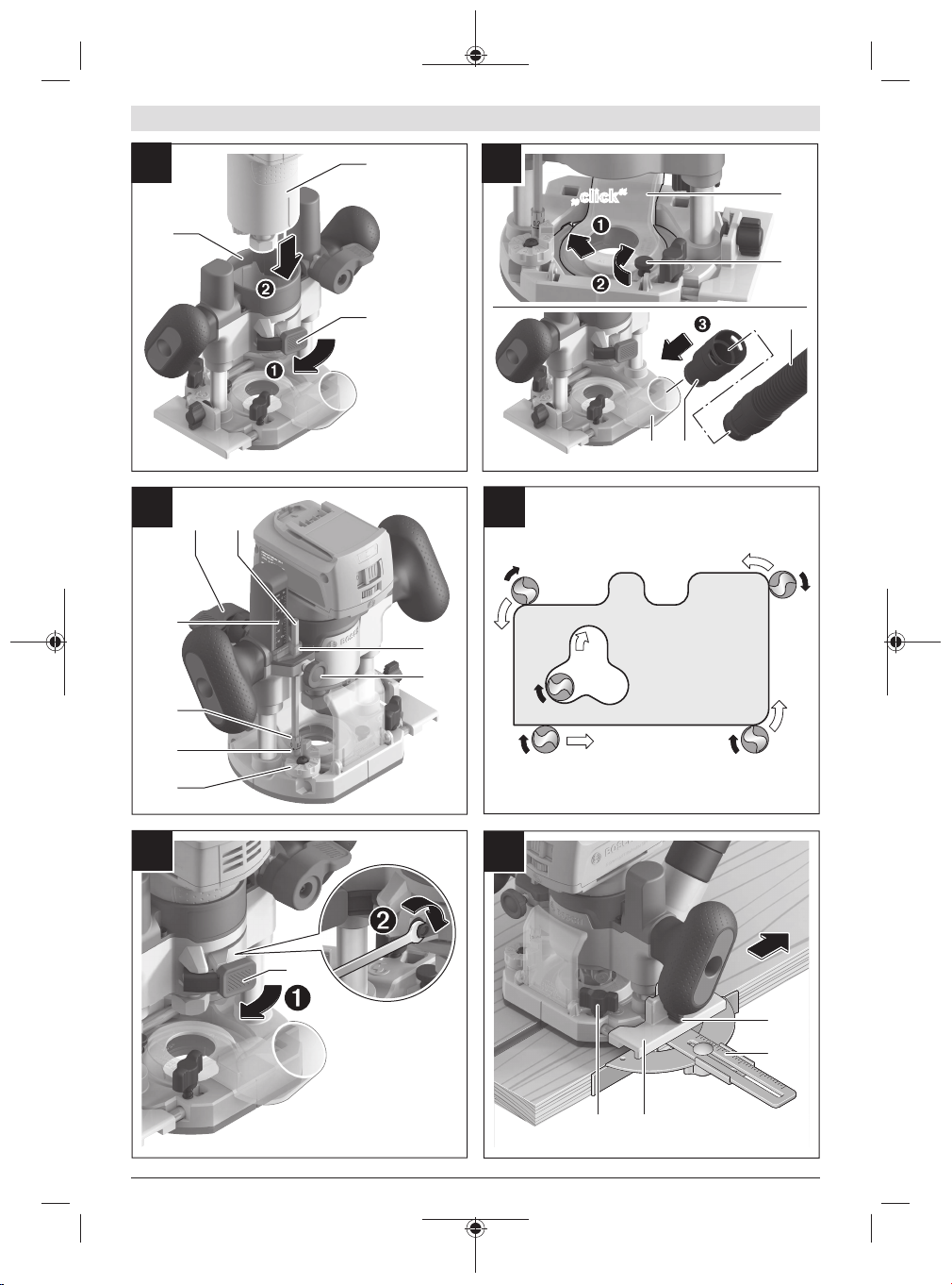
Connecting the Dust Extraction System (seefigureB)
Insert the dust extraction adapter(17) into the router
plunge base(2). Push the part of the adapter(17) that is op-
posite the screw(18) into the router plunge base(2). Fix
the adapter in place using the screw(18).
Put an extraction hose(26) (dia.35mm) (accessory) on the
installed dust extraction adapter(25). Connect the dust ex-
traction hose(26) to a dust extractor (accessory).
The dust extractor must be suitable for the material being
worked.
When extracting dust that is dry, especially detrimental to
health or carcinogenic, use a special dust extractor.
Operation
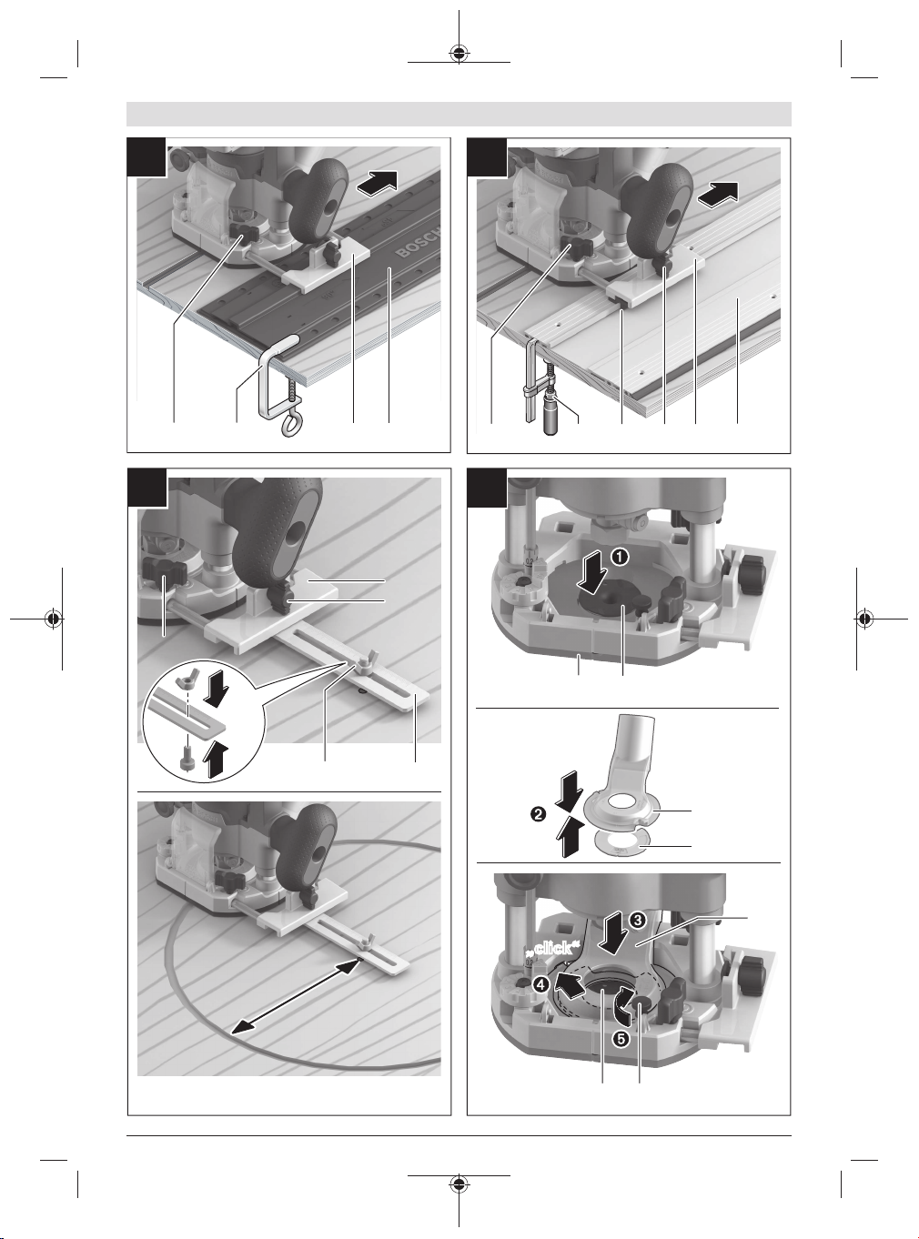
Setting the Routing Depth (seefigureC)
uThe routing depth must only be set while the power
tool is switched off.
Rough Adjustment of the Routing Depth using the
Infinitely Variable Depth Stop and Scale
– Place the power tool with a fitted router bit onto the work-
piece you want to machine.
– Set the scale for fine adjustment(10) to "0".
– Set the turret stop(8) to the lowest setting; you will feel
the turret stop engage.
– Loosen the handle screw for the depth stop(5) so that
the depth stop(3) moves freely.
– Slowly guide the router(1) by pressing the handle(14)
down slowly until the router bit is touching the workpiece
surface. Push the locking lever(12) to lock the plunge
depth.
– Push the depth stop(3) down until it is resting on the tur-
ret stop(8). Set the slide with the index mark(4) to posi-
tion "0" on the routing depth scale(11).
– Set the depth stop(3) to the required routing depth and
tighten the handle screw for the depth stop(5). Take care
not to accidentally move the index mark(4).
– Release the locking lever for the plunge action(12) and
guide the router to the uppermost position.
The set routing depth is only reached when the depth
stop(3) touches the turret stop(8) while plunging.
For larger routing depths, you should perform the cut in sev-
eral phases, so that only a small amount of material is re-
moved after each cut. By using the turret stop(8), the rout-
ing process can be divided into several steps.
Rough Adjustment of the Routing Depth using the Turret
Stop Settings
– Place the power tool with a fitted router bit onto the work-
piece you want to machine.
– Set the scale for fine adjustment(10) to "0".
– Set the turret stop(8) to the lowest setting you require;
you will feel the turret stop engage.
– Loosen the handle screw for the depth stop(5) so that
the depth stop(3) moves freely.
– Slowly guide the router(1) by pressing the handle(14)
down slowly until the router bit is touching the workpiece
surface. Push the locking lever(12) to lock the plunge
depth.
– Tighten the handle screw(5).
– By turning the turret stop(8), you can now set the depth
using the predefined settings.
Example:
Required routing depth: 8mm
First routing operation from setting "10" to setting
"5"5mm
Second routing operation from setting "5" to setting
"2"3mm
Note: For precision routing results, it is advisable to stay
within the maximum routing depth of 5mm per routing oper-
ation.
Fine Adjustment of the Routing Depth
After making a test cut, you can set the routing depth to the
exact level you require by turning the bushing(9). Turning it
clockwise increases the routing depth; turning it anticlock-
wise decreases the routing depth. The scale(10) can be
used for guidance. One turn corresponds to an adjustment
range of approx. 0.8mm; the maximum adjustment range is
approx. 4mm (i.e. five turns correspond to 4mm).
When the router plunge base(2) is lowered to the maximal
plunge depth, it is not possible to use the fine adjustment to
make deeper cuts, as the maximum adjustment range has
been utilised.
Fine adjustment is also not possible when the depth stop(3)
sits against the turret stop(8).
Working Advice
Routing Direction and Routing Process (seefigureD)
uRouting must always be carried out with the work-
piece being moved against the direction in which the
router bit is turning (up cut). If the workpiece is moved
in the same direction as the router bit is turning (down
cut), the power tool may be pulled out of your hands.
To rout with the router plunge base(2), proceed as follows:
– Set the required routing depth, (see "Setting the Routing
Depth (seefigureC) ", page10).
– Place the power tool with a fitted router bit onto the work-
piece you want to machine and switch on the power tool.
– Slowly guide the router(1) down until the set routing
depth is reached. Push the locking lever(12) to lock the
plunge depth.
– Carry out the routing process with a uniform feed.
– When routing is complete, move the router back to the
uppermost position.
– Switch the power tool off.
1 609 92A 8WV | (14.06.2023) Bosch Power Tools