9e1063 Page 2
CONTENTS
1. PREFACE
1.1 MANUFACTURER’S ADDRESS........................................................................................................................................................... 4
1.2 CUSTOMER SERVICE ........................................................................................................................................................................... 4
1.3 GUIDELINES, LAWS, STANDARDS.................................................................................................................................................... 4
1.3.1 DECLARATION OF CONFORMITY ................................................................................................................................................... 5
1.4 SUCCESSFUL MILKING.................................................................................................................................................................... 6
2. SAFETY
2.1 OWNER’S DUTY OF CARE ............................................................................................................................................................. 7
2.2 BASIC SAFETY INSTRUCTIONS.................................................................................................................................................... 8
2.3 PERSONNEL QUALIFICATION....................................................................................................................................................... 9
2.4 PROTECTIVE EQUIPMENT............................................................................................................................................................10
2.5 SAFETY SIGNS, STICKERS AND LABELS .................................................................................................................................10
2.6 PACKAGING MATERIALS ..............................................................................................................................................................10
2.7 CORRECT APPLICATION...............................................................................................................................................................10
2.8 DELIVERY............................................................................................................................................................................................12
2.9 STORAGE ...........................................................................................................................................................................................12
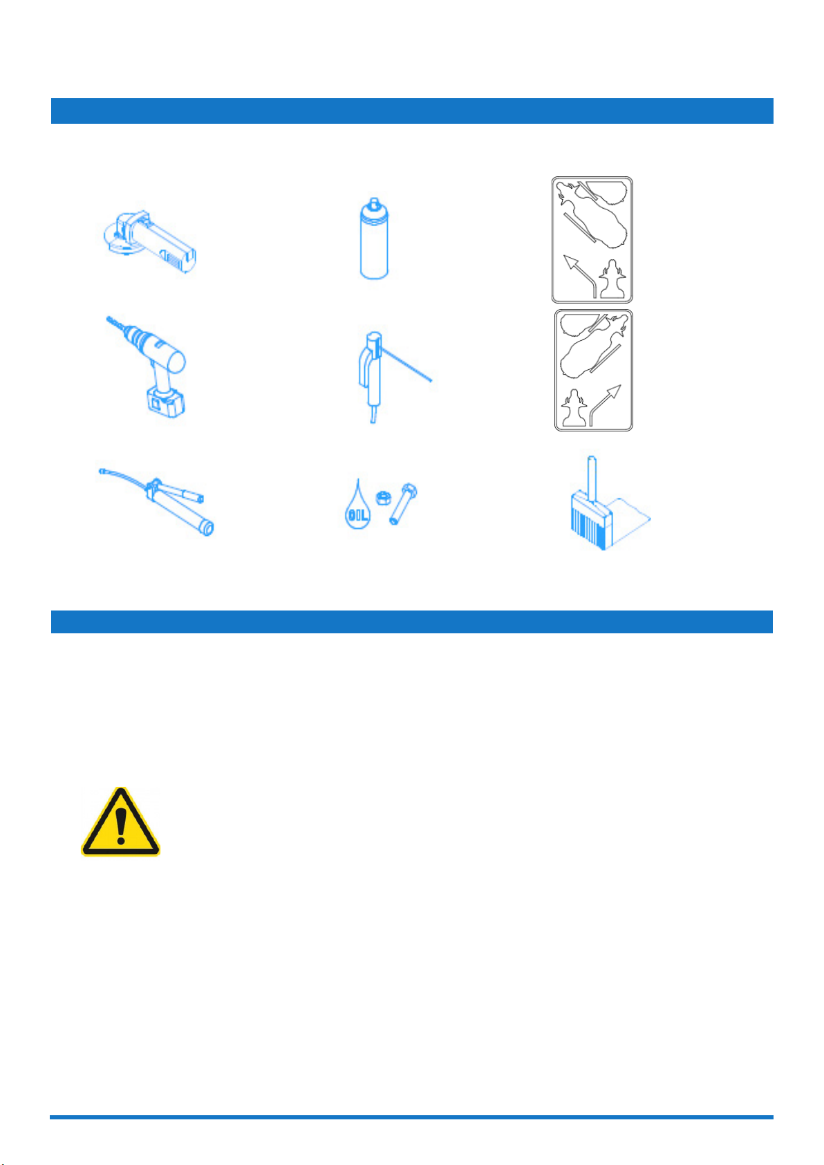
3. ASSEMBLY INSTRUCTIONS AND EXPLANATION OF SYMBOLS
3.1 ASSEMBLY INSTRUCTIONS ........................................................................................................................................................13
3.2 SYMBOLS ..........................................................................................................................................................................................14
3.3 RECOMMENDATIONS ...................................................................................................................................................................14
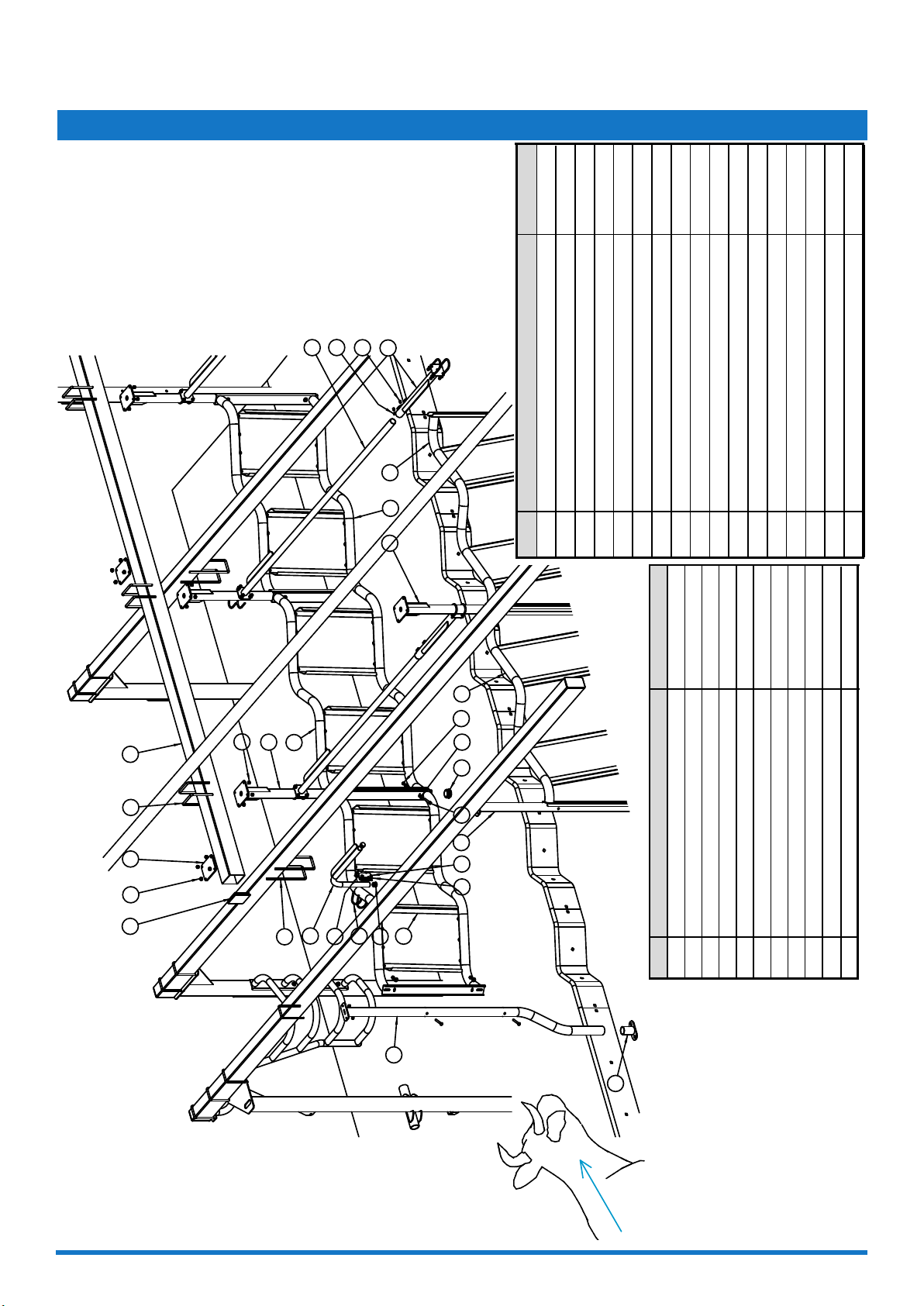
4. INSTALLATION
4.1 INDEXABLE MILKING PARLOR GT2 2X7 WITH INDEXING AND RAPID EXIT.............................................................15
4.2 INSTALLATION OF THE STRUCTURAL PARTS.........................................................................................................................................................................16
4.3 INSTALLATION OF THE GATE POST AND THE ENTRANCE BARRIER ...........................................................................17
4.4 BITUMEN PROTECTIVE COATING ............................................................................................................................................18
4.5 INSTALLATION OF THE RUMP RAIL .........................................................................................................................................19
4.6 INSTALLATION OF THE KNIFE GATE .......................................................................................................................................20
4.7 INSTALLATION OF THE END BARRIER.....................................................................................................................................21
4.8 INSTALLATION OF THE PNEUMATIC EXIT REEL .................................................................................................................22
4.9 INSTALLATION OF THE PNEUMATIC EXIT REEL DRIVE ....................................................................................................23
4.10 INSTALLATION OF THE PNEUMATICALLY ACTUATED LOCK..........................................................................................24
4.11 INSTALLATION OF THE INDEXING CYLINDER ....................................................................................................................25
4.12 OPTION: INSTALLATION OF THE SINUS CURBING ..........................................................................................................26
4.13 OPTION: INSTALLATION OF THE DETACHER CYLINDER BRACKET..............................................................................28
5. AUTOMATISATION, CONTROLLING, STARTUP AND FINAL TEST
5.1 USER CONTROLS.............................................................................................................................................................................29
5.2 INSTALLATION..................................................................................................................................................................................29
5.3 ELECTRIC WIRING RECOMMENDATION.................................................................................................................................30
5.4 END OFF STROKE ADJUSTMENT..............................................................................................................................................30
5.5 BUTTON BOX CONTROL ..............................................................................................................................................................30
5.6 CONTOL AND ADJUSTMENT OFF THE PHOTOCELL OPTION.....................................................................................30
5.7 TESTS ...................................................................................................................................................................................................31
5.8 ADJUSTING DURATION OF REEL IN HORIZONTAL REST POSITION ...........................................................................31
5.9 ADJUSTING INDEXING DELAY AFTER GATE CLOSURE 0 TO 10 SECONDS............................................................32
5.10 MAINTENANCE................................................................................................................................................................................32