Bray 71 Series User manual

SERIES
ELECTRIC ACTUATOR
Installation Operation and Maintenance Manual
THE HIGH PERFORMANCE COMPANYBRAYCOMMERCIALDIVISION.COM

This Page Intentionally Left Blank

1
Series 71 – Electric Actuator
Installation, Operation and Maintenance Manual
FOR MORE INFORMATION ON THIS PRODUCT AND OTHER BRAY PRODUCTS
PLEASE VISIT OUR WEBSITE – www.braycommercialdivision.com
Table of Contents
2. DEFINITION OF TERMS . . . . . . . . . . . . . . . . . . . . . . . . . . . . . . . . . . . . 2
3. SAFETY . . . . . . . . . . . . . . . . . . . . . . . . . . . . . . . . . . . . . . . . . . . . . 2
3.1. HAZARD-FREE USE. . . . . . . . . . . . . . . . . . . . . . . . . . . . . . . . . . .2
3.2. QUALIFIED PERSONNEL . . . . . . . . . . . . . . . . . . . . . . . . . . . . . . . .3
4. INTRODUCTION . . . . . . . . . . . . . . . . . . . . . . . . . . . . . . . . . . . . . . . . .3
5. PART NUMBERING SYSTEM . . . . . . . . . . . . . . . . . . . . . . . . . . . . . . . . . . 4
6. PRINCIPLE OF OPERATION . . . . . . . . . . . . . . . . . . . . . . . . . . . . . . . . . . 4
6.1. ELECTRICAL OPERATION . . . . . . . . . . . . . . . . . . . . . . . . . . . . . . . 5
6.2. MECHANICAL OPERATION . . . . . . . . . . . . . . . . . . . . . . . . . . . . . . 5
7. ACTUATION . . . . . . . . . . . . . . . . . . . . . . . . . . . . . . . . . . . . . . . . . . . 5
7.1. MANUAL OPERATION . . . . . . . . . . . . . . . . . . . . . . . . . . . . . . . . . 5
7.2. REMOTE OPERATION. . . . . . . . . . . . . . . . . . . . . . . . . . . . . . . . . .5
7.2.1. S71 120VAC ON/OFF ACTUATOR WITH INTERPOSING RELAY BOARD . . . . . 6
7.2.2. S71 24V ON/OFF ACTUATOR WITH ON/OFF CONTROLLER . . . . . . . . . . . 8
7.2.3. S71 120VAC MODULATING ACTUATOR WITH S71 SERVO CONTROLLER . . . 10
7.2.4
S71 24V MODULATING ACTUATOR S71 SERVO CONTROLLER. . . . . . . 11
8. STORAGE . . . . . . . . . . . . . . . . . . . . . . . . . . . . . . . . . . . . . . . . . . . 13
9. COMMISSIONING . . . . . . . . . . . . . . . . . . . . . . . . . . . . . . . . . . . . . . . 13
9.1. MOUNTING THE ACTUATOR. . . . . . . . . . . . . . . . . . . . . . . . . . . . . 13
9.2. WIRING THE ACTUATOR . . . . . . . . . . . . . . . . . . . . . . . . . . . . . . . 14
9.3. SETTING TRAVEL LIMIT SWITCHES. . . . . . . . . . . . . . . . . . . . . . . . . 14
10. MAINTENANCE . . . . . . . . . . . . . . . . . . . . . . . . . . . . . . . . . . . . . . . . 15
11. INSTALLABLE OPTIONS . . . . . . . . . . . . . . . . . . . . . . . . . . . . . . . . . . . 15
11.1. HEATER . . . . . . . . . . . . . . . . . . . . . . . . . . . . . . . . . . . . . . . . 15
11.2. SPINNER . . . . . . . . . . . . . . . . . . . . . . . . . . . . . . . . . . . . . . . . 16
11.3. RECEPTACLES. . . . . . . . . . . . . . . . . . . . . . . . . . . . . . . . . . . . . 16
12. 12.0. APPENDIX A: BASIC TOOLS . . . . . . . . . . . . . . . . . . . . . . . . . . . . . 17
11. 13.0. APPENDIX B: ACTUATOR TROUBLESHOOTING CHART . . . . . . . . . . . . . 18
12. 14.0. APPENDIX C: ACTUATOR EXPLODED VIEW. . . . . . . . . . . . . . . . . . . . 19
13. 15.0. APPENDIX D: COVER EXPLODED VIEW . . . . . . . . . . . . . . . . . . . . . . 20
14. 16.0. APPENDIX E: BASE EXPLODED VIEW . . . . . . . . . . . . . . . . . . . . . . . 21
15. 17.0. APPENDIX F: INDICATOR SHAFT EXPLODED VIEW . . . . . . . . . . . . . . . 22
16. 18.0. APPENDIX G: MOTOR EXPLODED VIEW . . . . . . . . . . . . . . . . . . . . . . 23

2
Series 71 – Electric Actuator
Installation, Operation and Maintenance Manual
READ AND FOLLOW THESE INSTRUCTIONS
SAVE THESE INSTRUCTIONS
2.0 DEFINITION OF TERMS
WARNING
Indicates a potentially hazardous situation which if not avoided could result in death
or serious injury
CAUTION
Indicates a potentially hazardous situation which if not avoided may result in minor
or moderate injury
NOTICE
Indicates a potential situation which if not avoided may result in an undesirable result
or state including property damage
3.0 SAFETY
HAZARD FREE USE
This device left the factory in proper condition to be safely installed and
operated in a hazard-free manner. The notes and warnings in this document
must be observed by the user to ensure hazard-free operation of this device.
All necessary precautions need to be taken to prevent damage due to rough
handling, impact, or improper storage. Do not use abrasive compounds to
clean the device, or scrape its surfaces with any objects.
Configuration and setup procedures for this device are described in this
manual. Proper configuration and setup are required for the safe operation of
this device.
The control system in which this device is installed must have proper
safeguards to prevent injury to personnel, or damage to equipment, should a
failure of system components occur.
WARNING
The device generates large mechanical force during normal operation

3
Series 71 – Electric Actuator
Installation, Operation and Maintenance Manual
3.2 QUALIFIED PERSONNEL
WARNING
The actuator must only be installed commissioned operated and repaired by qualified
personnel
Installation commissioning operation and maintenance must be performed under
strict observation of all applicable codes standards and safety regulations
As per this document, a qualified person is one who is trained in:
The operation and maintenance of electric equipment and systems in
accordance with established safety practices.
Procedures to energize, de-energize, ground, tag and lock electrical circuits
and equipment in accordance with established safety practices.
The proper use and care of personal protective equipment (PPE) in
accordance with established safety practices.
First aid.
4.0 INTRODUCTION
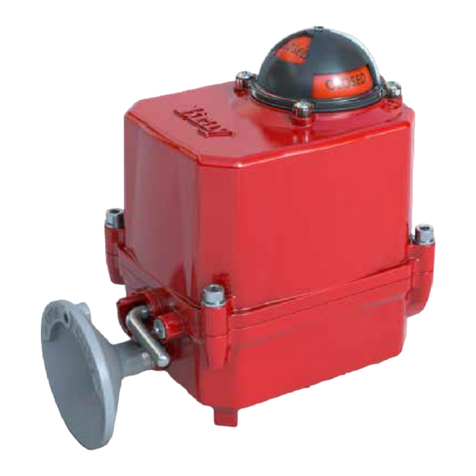
The Bray Series 71 is a quarter turn electric actuator with manual
declutchable override for use on any quarter turn valve or device requiring up
to 531 lbs-in (60 Nm) of torque. Standard operating speed is 30 seconds for
single phase line powered units. Operational speed of 24VAC/DC units are
dependent on torque and supply voltage. All units are rated for 50% duty, 5
minutes max on time.
25
30
35
40
45
50
55
60
21 22 23 24 25 26 27
Quarter Turn Speed [s]
Supply Voltage [V]
24V Speed versus Supply at 531 lb-in [60Nm]
24VAC
24VDC

4
Series 71 – Electric Actuator
Installation, Operation and Maintenance Manual
5.0 PART NUMBERING SYSTEM - REFERENCE CHART
6.0 PRINCIPLE OF OPERATION
The Series actuator is divided into two internal sections the drive train
below the switch plate and the motor and control center above the switch
plate Below the switch plate the motor drives a system of spur gears
The manual declutch override for manual operation is housed here as well
Above the switch plate is where user required readily accessible components
are placed The indicator shaft assembly limit switches terminals heater
and electronic controllers are all placed here for easy access
External to the unit is a large and easy to read indicator manual declutch
override and dual conduit entry ports The external coating is a high-quality
polyester powder coat which has exceptional UV protection and chemical
resistance
Series – Torque Options – Actuator Control Voltage – Trim
– – D –
Series
Series - QTR Turn
Torque
lbf-in Nm
Options
Standard - Aux Switches
Aux Switches Heater
Mounting and Conduit Control Type Notes
D Imperial ONOFF IRB or Controller
G Imperial Modulating S Servo
N Metric ONOFF IRB or Controller
R Metric Modulating S Servo
Voltage
VAC
VACVDC
VAC
Coating
Red Polyester

5
Series 71 – Electric Actuator
Installation, Operation and Maintenance Manual
ELECTRICAL OPERATION
The motors used in the Bray Series are of either permanent split capacitor
(PSC) design for single phase line applications or permanent magnet (PM)
design for ACDC power Travel limit switches are mechanical form
(SPDT) with contact rated at A VAC
The PSC motor is designed for impedance protection such that the current
and self-heating will be limited in cases where the torque capacity of
the unit is exceeded to the point where the motor stalls The PM motor
controllers implement self-resetting over-current protection which will also
limit the current and torque capacity of the motor
MECHANICAL OPERATION
Mechanically the ratio of the gearing determines the output speed of
the unit The actuator utilizes high efficiency spur gears Positioning is
determined by an indicatorcam shaft which is linked to the output shaft In
the declutched position the manual override drives the output
7.0 ACTUATION
MANUAL OPERATION
The Bray Series actuators are provided with a declutchable manual
override system To manually operate the actuator push in the manual
override button and rotate the declutchable lever counter-clockwise until it
reaches the o’clock position Once the declutchable lever is in position
turn the handwheel until the valve reaches the required position The motor
does not shutoff during manual operation and will continue to rotate the
upper gearing if being commanded by the process Push in the manual
override button and rotate the declutchable lever clockwise until it reaches
the o’clock position to re-engage the upper gearing and motor drive
Manual Override Button
Manual Override Lever
REMOTE OPERATION
CAUTION
Verify that the main electric power supplied to the actuator is in compliance with
the specifications on the actuator label
Engaging the handwheel before or during the application of a supply voltage will
prevent the actuator motor from driving the valve to the position commanded by
the process

6
Series 71 – Electric Actuator
Installation, Operation and Maintenance Manual
S VAC ONOFF ACTUATOR WITH INTERPOSING RELAY BOARD
The back feeding of one actuator by another one wired in parallel is
eliminated by using the S IRB If the actuator is running Open and the
customer switches “instantaneously” to run Closed the Open relay will take
time to “drop-out” and the Close relay will take time to “pull-in” This time
lapse is ~ms The time delay provided by the S IRB will protect the
switches and gears from the controller’s instantaneous command signal
reversal Current draw and field wiring are not affected by the IRB
NOTE The host controller should use a one second time delay for command
signal reversal
CAUTION
Apply voltage to only one direction terminal at a time
WD-000545
NOTES:
1. HEATER IS OPTIONAL.
2. HEATER LIVE CONNECTION IS REQUIRED WHEN A HEATER IS INSTALLED.
3. AUXILIARY SWITCHES ARE VOLTAGE FREE, RATED FOR 3A, 125/250VAC.
4. AUXILIARY SIGNAL OUT IS SAME VOLTAGE AS AUXILIARY SIGNAL IN.
5. LIVE, NEUTRAL, & GROUND ARE A SINGLE PHASE POWER SUPPLY.
6. ALL SWITCHES SHOWN IN DEACTIVATED STATE.
FIELD TERMINALS
·14-24 AWG MAX RANGE, 18 AWG RECOMMENDED
·PUSH BUTTON CLAMP
·105 °C, 300V MIN RATED WIRE
·STRIP WIRE: .39"-.43" [10-11mm]
·GROUND WIRE GAUGE TO BE EQUAL TO LARGEST SUPPLY CONDUCTOR.

7
Series 71 – Electric Actuator
Installation, Operation and Maintenance Manual
S VAC ONOFF ACTUATOR WITH INTERPOSING RELAY BOARD
S VAC ONOFF ACTUATOR WITH INTERPOSING RELAY ASSEMBLY

8
Series 71 – Electric Actuator
Installation, Operation and Maintenance Manual
S V ONOFF ACTUATOR WITH ONOFF CONTROLLER
Whether supplying AC or DC power the V OnOff Controller provides
a reference direction signal and DC power to an H-bridge to power and
control motor direction The controller will handle instantaneous switching
of the command signal and enforce a short timing delay In the case of a
control fault where both directions are commanded at once the controller
will stop actuator movement In the case of an over torque fault the
H-bridge is also configured to limit max current which will effectively lock
the rotor
CAUTION
Apply voltage to only one direction terminal at a time
WD-000544
NOTES: FIELD TERMINALS
·14-24 AWG MAX RANGE, 18 AWG RECOMMENDED
·PUSH BUTTON CLAMP
·105 °C, 300V MIN RATED WIRE
·STRIP WIRE: .39"-.43" [10-11mm]
·
GROUND WIRE GAUGE TO BE EQUAL TO LARGEST SUPPLY CONDUCTOR.
1. HEATER IS OPTIONAL.
2. AUXILIARY SWITCHES ARE VOLTAGE FREE, RATED FOR 3A, 125/250VAC.
3. AUXILIARY SIGNAL OUT IS SAME VOLTAGE AS AUXILIARY SIGNAL IN.
4. LIVE, NEUTRAL, & GROUND ARE A SINGLE PHASE POWER SUPPLY.
5. IF USING VAC POWER SUPPLY, SUPPLY TO BE RATED 100VA, CLASS 2
6. ALL SWITCHES SHOWN IN DEACTIVATED STATE.
SERIES 71

9
Series 71 – Electric Actuator
Installation, Operation and Maintenance Manual
S VAC ONOFF ACTUATOR WITH ONOFF CONTROLLER BOARD
S VAC ONOFF ACTUATOR WITH ONOFF CONTROLLER ASSEMBLY

10
Series 71 – Electric Actuator
Installation, Operation and Maintenance Manual
S VAC MODULATING ACTUATOR S SERVO CONTROLLER
Power connection that energizes the S Servo and powers the actuator
under control The voltage supplied should be based on the actuator
nameplate voltage and the voltage listed on the S Servo label
The S Servo has an onboard protective fuse that is in line with the input
power connection This protective fuse is rated for A
See S Servo Manual at braycommercialcom for more details
To control the actuator remotely from a process controller in a modulating
application the user must apply the proper supply voltage and the
configured control signal to the S Servo electronics package The control
signal may be applied locally from a hand-held signal generator or remotely
from a process controller
In the case of an over torque fault the electronics are configured to limit
max current which will effectively lock the rotor
For more information please refer to the S S Servo Manual This manual
is available on the company website (wwwbraycommercialdivisioncom)
Xref C:\BII_Vault\Global\Templates\ACAD\LogoBrayControls1.dwg Xref C:\BII_Vault\Global\Templates\ACAD\LogoBrayControls1.dwg
WD-000579
------
BUSA
S71
120/230V S71 SERVO
AND HEATER (OPTIONAL)
1
NOT RELEASED - DO NOT MANUFACTURE
WD-000579
------
BUSA
S71
120/230V S71 SERVO
AND HEATER (OPTIONAL)
1
NOT RELEASED - DO NOT MANUFACTURE
120/230V
S71 SERVO
(SEE NOTES 7-9)
(SEE NOTES 8-11)
INPUT (+)
INPUT (-)
OUTPUT(+)
OUTPUT(-)
SIGNAL
LIVE
NEUTRAL
POWER
120/230V S71
SERVO
(SEE NOTES 7-9)
(SEE NOTES 8-11)
INPUT (+)
INPUT (-)
OUTPUT(+)
OUTPUT(-)
SIGNAL
LIVE
NEUTRAL
POWER
LIMIT
OPEN
LIMIT
CLOSE
LIMIT CLOSE
POT WIPER
POT COM
LIMIT
OPEN
POT V+
LIVE
NEUTRAL
MOTOR
MOTOR CL
NEUTRAL
CAP
CLOSE
MOTOR OP
CAPACITOR
CAP
OPEN
HEATER
NOTES:
1. HEATER IS OPTIONAL.
2. LIVE, NEUTRAL, & GROUND ARE A SINGLE PHASE POWER SUPPLY.
3. ALL SWITCHES SHOWN IN DEACTIVATED STATE.
4. WHEN USING 0-10VDC MODE,THE COMMON OF THE COMMAND SIGNAL
SHOULD NOT BE GROUND/EARTH REFERENCED.
5. COMMAND SIGNAL AND FEEDBACK SIGNAL MUST BE ISOLATED FROM EACH
OTHER AND ANY OTHER CIRCUITS.
6. COMMAND SIGNAL & FEEDBACK SIGNAL WIRES SHOULD BE SHIELDED
PROPERLY & SHIELD SHOULD BE GROUNDED/EARTHED ON ONE END ONLY,
PREFERABLYTHE CONTROLLER END.
7. FEEDBACK LOOP IS POWERED BY THE SERVO, DO NOT SUPPLY
EXTERNAL POWER.
8. POSITION FEEDBACK DEVICE LOAD IS NOT TO EXCEED 400 OHMS IN
THE 4-20mA CONFIGURATION.
HEATER
(OPTIONAL)
CAM
#4
N.O.
COM N.C.
CAM
#3
N.O.
COM N.C.
CAM
#2
N.O.
COM N.C.
CLOSE
CAM
#1
N.O.
COM N.C.
OPEN
AUX
CLOSE
AUX
OPEN
SWITCH PCB
ACTUATOR
FIELD WIRING
GROUND
NEUTRAL
LIVE
-
+
-
+
POSITION
FEEDBACK
DEVICE
OUTGOING FEEDBACK
SIGNAL (SHIELDED)
COMMAND
SIGNAL
DEVICE
INCOMING COMMAND
SIGNAL (SHIELDED)
CALIBRATION SEQUENCE:
1. CONNECT POWER SUPPLY.
2. SET INPUT AND OUTPUT SIGNAL MODES.
3. CALIBRATETHE INPUT SIGNAL.
·DISCONNECT ALL SIGNAL WIRES FROM INPUT(+)/(-).
·FOR 0-10V, 0-5V, AND 2-10V MODES, SHORT INPUT
(+) TO INPUT (-).
·PRESS THE "CALIBRATE" BUTTON FOR 2 SECONDS.
·IMMEDIATELY PRESS THE INPUT SIGNAL BUTTON.
4. RE-ATTACH THE INPUT SIGNAL WIRES.
5. PRESS THE "CALIBRATE" BUTTON FOR TWO SECONDS.
6. ACTUATOR WILL SELF-CALIBRATE.
TERMINALS - ELECTRONICS
·14-24 AWG MAX RANGE, 18 AWG RECOMMENDED
·PUSH BUTTON CLAMP
·105 °C, 300V MIN RATEDWIRE
·STRIP WIRE: .39"-.43" [10-11mm]
·GROUND WIRE GAUGETO BE EQUALTO LARGEST
SUPPLY CONDUCTOR.
FEEDBACK
POTENTIOMETER
POT PCB
GROUND
NEUTRAL
LIVE
-
+
-
+
POSITION
FEEDBACK
DEVICE
COMMAND
SIGNAL
DEVICE
ACTUATOR
WD-000579 REV 1
FIELD
WIRING
CALIBRATION SEQUENCE:
1. CONNECT POWER SUPPLY.
2. SET INPUT AND OUTPUT SIGNAL MODES.
3. CALIBRATETHE INPUT SIGNAL.
·DISCONNECT ALL SIGNAL WIRES FROM INPUT(+)/(-).
·FOR 0-10V, 0-5V, AND 2-10V MODES, SHORT INPUT
(+) TO INPUT (-).
·PRESS THE "CALIBRATE" BUTTON FOR 2 SECONDS.
·IMMEDIATELY PRESS THE INPUT SIGNAL BUTTON.
4. RE-ATTACH THE INPUT SIGNAL WIRES.
5. PRESS THE "CALIBRATE" BUTTON FOR TWO SECONDS.
6. ACTUATOR WILL AUTOMATICALLY COMPLETE
SELF-CALIBRATION.
FIELD CONNECTIONS:
14-24 AWG, 18 AWG
RECOMMENDED
105 °C, 300V MIN
RATED WIRE.
STRIP WIRE: .39"-
.43" [10-11mm]
GROUND WIRE GAUGE
TO BE EQUALTO
LARGEST SUPPLY
CONDUCTOR.
O C
BLACK
BLACK
BLACK
RED
GREY
BLUE
RED
WHITE
BLACK
NOTES:
1. HEATER IS OPTIONAL.
2. LIVE, NEUTRAL, & GROUND ARE A SINGLE PHASE POWER SUPPLY.
3. ALL SWITCHES SHOWN IN DEACTIVATED STATE.
4. WHEN USING 0-10VDC MODE,THE COMMON OF THE COMMAND SIGNAL
SHOULD NOT BE GROUND/EARTH REFERENCED.
5. COMMAND SIGNAL AND FEEDBACK SIGNAL MUST BE ISOLATED FROM EACH
OTHER AND ANY OTHER CIRCUITS.
6. COMMAND SIGNAL & FEEDBACK SIGNAL WIRES SHOULD BE SHIELDED
PROPERLY & SHIELD SHOULD BE GROUNDED/EARTHED ON ONE END ONLY,
PREFERABLYTHE CONTROLLER END.
7. FEEDBACK LOOP IS POWERED BY THE SERVO, DO NOT SUPPLY
EXTERNAL POWER.
8. POSITION FEEDBACK DEVICE LOAD IS NOT TO EXCEED 400 OHMS IN
THE 4-20mA CONFIGURATION.
N
OC
GREY
BLACK
WHITE
MOTOR
6W
2
3
1
4
TERMINALS - AUX
·12-22 AWG MAX RANGE, 18
AWG RECOMMENDED
·SCREW CLAMP WITH WIRE
PROTECTOR
·105 °C, 300V MIN RATEDWIRE
·TORQUE SCREW TO 5.5 IN-LBS
·STRIP WIRE: .177"-.217"
[4.5-5.5mm]
TERMINALS - ELECTRONICS
·14-24 AWG MAX RANGE, 18 AWG RECOMMENDED
·PUSH BUTTON CLAMP
·105 °C, 300V MIN RATEDWIRE
·STRIP WIRE: .39"-.43" [10-11mm]
·GROUND WIRE GAUGETO BE EQUALTO LARGEST
SUPPLY CONDUCTOR.
TERMINALS - AUX
·12-22 AWG MAX RANGE, 18
AWG RECOMMENDED
·SCREW CLAMP WITH WIRE
PROTECTOR
·105 °C, 300V MIN RATEDWIRE
·TORQUE SCREW TO 5.5 IN-LBS
·STRIP WIRE: .177"-.217"
[4.5-5.5mm]
AUX OPEN
AUX CLOSE
AUX COM

11
Series 71 – Electric Actuator
Installation, Operation and Maintenance Manual
WD-000543
NOTES:
1. HEATER IS OPTIONAL.
2. AUXILIARY SWITCHES ARE VOLTAGE FREE, RATED FOR 3A, 125/250VAC.
3. AUXILIARY SIGNAL OUT IS SAME VOLTAGE AS AUXILIARY SIGNAL IN.
4. LIVE, NEUTRAL, & GROUND ARE A SINGLE PHASE POWER SUPPLY.
5. ALL SWITCHES SHOWN IN DEACTIVATED STATE.
6. IF USING VAC POWER SUPPLY, TO BE RATED 100VA, CLASS 2.
7. WHEN USING 0-10VDC MODE, THE COMMON OF THE COMMAND SIGNAL
SHOULD NOT BE GROUND/EARTH REFERENCED.
8. COMMAND SIGNAL AND FEEDBACK SIGNAL MUST BE ISOLATED FROM EACH
OTHER AND ANY OTHER CIRCUITS.
9. COMMAND SIGNAL & FEEDBACK SIGNAL WIRES SHOULD BE SHIELDED
PROPERLY & SHIELD SHOULD BE GROUNDED/EARTHED ON ONE END ONLY,
PREFERABLY THE CONTROLLER END.
10. FEEDBACK LOOP IS POWERED BY THE SERVO, DO NOT SUPPLY
EXTERNAL POWER.
11. POSITION FEEDBACK DEVICE LOAD IS NOT TO EXCEED 400 OHMS IN
THE 4-20mA CONFIGURATION.
CALIBRATION SEQUENCE:
1. CONNECT POWER SUPPLY.
2. SET INPUT AND OUTPUT SIGNAL MODES.
3. CALIBRATE THE INPUT SIGNAL.
·DISCONNECT ALL SIGNAL WIRES FROM INPUT(+)/(-).
·FOR 0-10V, 0-5V, AND 2-10V MODES, SHORT INPUT
(+) TO INPUT (-).
·PRESS THE "CALIBRATE" BUTTON FOR 2 SECONDS.
·IMMEDIATELY PRESS THE INPUT SIGNAL BUTTON.
4. RE-ATTACH THE INPUT SIGNAL WIRES.
5. PRESS THE "CALIBRATE" BUTTON FOR TWO SECONDS.
6. ACTUATOR WILL SELF-CALIBRATE.
FIELD TERMINALS
·
14-24 AWG MAX RANGE, 18 AWG RECOMMENDED
·
PUSH BUTTON CLAMP
·
105 °C, 300V MIN RATED WIRE
·
STRIP WIRE: .39"-.43" [10-11mm]
·
GROUND WIRE GAUGE TO BE EQUAL TO LARGEST
SUPPLY CONDUCTOR.
SERVO 71
S V MODULATING ACTUATOR S SERVO CONTROLLER
Power connection that energizes the S Servo and powers the actuator
under control The voltage supplied should be based on the actuator
nameplate voltage and the voltage listed on the S Servo label
The S Servo has an onboard protective fuse that is in line with the input
power connection This protective fuse is rated for A
See S Servo Manual at braycommercialcom for more details
To control the actuator remotely from a process controller in a modulating
application the user must apply the proper supply voltage and the
configured control signal to the S Servo electronics package The control
signal may be applied locally from a hand-held signal generator or remotely
from a process controller
The V S Servo may be powered from either VDC or a VAC VA
Class power supply In the case of an over torque fault the electronics are
configured to limit max current which will effectively lock the rotor
For more information please refer to the S Servo Manual This manual is
available on the company website (wwwbraycommercialdivisioncom)

12
Series 71 – Electric Actuator
Installation, Operation and Maintenance Manual
S VAC MODULATING ACTUATOR WITH SEVRO S BOARD
S VAC MODULATING ACTUATOR WITH S SERVO ASSEMBLY

13
Series 71 – Electric Actuator
Installation, Operation and Maintenance Manual
8.0 STORAGE
WARNING
Actuators are not weatherproof unless they are properly installed on the valve or
prepared for storage Bray cannot accept responsibility for deterioration caused
on-site
Store units on a shelf or wooden pallet in order to protect against floor
dampness
Cover the units to protect against dust and dirt
To prevent condensation from forming inside these units maintain a near
constant external temperature and store in a well-ventilated clean dry room
away from vibration
For units with an internal heater power should be supplied to the heater via
conduit entry with an appropriate sealing gland
9.0 COMMISSIONING
MOUNTING THE ACTUATOR
All Bray Series electric actuators are suitable for direct mounting on Bray
valves With proper mounting hardware the S actuator can be installed
onto other quarter-turn valves or devices
NOTICE
• The standard mounting position for the actuator orients the unit with its handwheel
in a vertical plane and parallel to the pipeline
• If the actuator is mounted on a vertical pipe it is recommended that the unit be
positioned with the conduit entries on the bottom to prevent condensation from
entering the actuator through its conduits
• In all cases the conduit should be positioned to prevent drainage into the actuator
X
X X
Follow the steps below to mount the actuator onto the valve.
•
Manually operate the actuator until the output shaft of the actuator is in line with the
valve stem. If possible, select an intermediate position for both the valve and actuator.
• If required, place the proper adapter onto the valve stem. It is recommended that a
small amount of ‘anti-seize’ lubricant be applied to the adapter to ease assembly.
• Mount the actuator onto the valve stem.
• Install the furnished mounting studs by threading studs all the way into the actuator
base. It may be necessary to manually operate the actuator to align the valve and
actuator bolt patterns.
• Fasten the mounting studs in place with furnished hex nuts and lock washers.

14
Series 71 – Electric Actuator
Installation, Operation and Maintenance Manual
WIRING THE ACTUATOR
WARNING
Turn off all power and lockouttag out service panel before installing or modifying any
electrical wiring
SETTING TRAVEL LIMIT SWITCHES
WARNING
• Ensure a ground wire is attached to one of the two ground wire locations and
follow proper grounding techniques as required by applicable codes standards and
safety regulations
Standard factory setting of the travel limit switches allows 90° travel between open and
close positions. Cams for each switch are adjustable for applications where less than
90-degree travel is desired between the open and closed positions.
.
•
Manually operate the actuator to the closed position.
• Using a hex key, loosen the set screw on the Close limit switch cam.
• Adjust the cam until it activates the limit switch. The limit switch will “click” when
activated.
• Tighten the set screw.
• Adjust the Closed auxiliary switch such that it advances slightly past the closed limit
switch.
• Repeat in the open position with the open cams.
• Take the actuator cover o. The cover should be kept on hand for reference.
•
Wire the actuator as per the wiring diagram attached to the inside of the actuator cover.
NOTICE
• Power and control wiring should use separate conduit entries
• A minimum of AWG wire is recommended for all field wiring
• Field wiring terminals are push button type with wire clamps and can accept wire
gauge from to AWG
• Wires to be stripped - [-mm]
• The conduit connections must be properly sealed to maintain the weather proof
integrity of the actuator enclosure
• Only one wire is allowed per terminal entry
NOTICE
If the unit came assembled to a valve the switches have been factory-set and
DO NOT need adjustment

15
Series 71 – Electric Actuator
Installation, Operation and Maintenance Manual
11.0 INSTALLABLE OPTIONS
HEATER
Bray offers an optional heater as a factory installable option for the Series
actuator to prevent condensation from forming inside the actuator
Units with OnOff actuation use a positive temperature coefficient (PTC)
style heater which has a unique temperature – resistance characteristic The
heater self-regulates by increasing its electrical resistance relative to the
internal temperature The heater does not require external thermostats or
switches to control its heat output VACVAC OnOff units require
dedicated live to power the heater
Modulating units use a resistive element controlled by an on-board
thermostat
NOTICE
The heater must have a constant power supply to be effective
WARNING
The heater surface can reach temperatures in excess of F (C)
10.0 MAINTENANCE
While the S has been designed for minimal maintenance requirements it
is suggested that an operator dustclean the unitreview operation every
months cycles or as required by the required site maintenance plan
WARNING
In the case of disassembly ensure that all mechanical forces that could affect
the position of the quarter turn device are removed prior to loosening of the S
mounting bolts
CAUTION
Before re-installing the cover
• Ensure that there is no dirt or debris on the cover seal and mating surfaces
• Ensure that the cover seal is in place and not damaged

16
Series 71 – Electric Actuator
Installation, Operation and Maintenance Manual
SPINNER
A spinner is field installable attachment to the actuator handwheel to ease
and speed the manual operation of the Series actuator Spinners are
provided with each actuator
RECEPTACLES
Bray offers plug-in receptacles as a field or factory option for quick and easy
field wiring of Series actuators Cord sets to fit these connectors can also
be ordered in several lengths Unless otherwise specified power receptacles
will be -pin mini style standard duty with a black anodized aluminum
finish They conform to ANSI BM except in wire color Euro receptacles
will be used for low power instrument and signal cable since they can be
supplied shielded Wiring diagrams for plug-in receptacles will be provided
as a separate diagram Units ordered with pin connector receptacles factory
installed are wired and tested
Receptacle Kit:
• Receptacle(s), male pin and male thread.
• NPT (M20), in the quantity, style, and number of pins ordered.
Tools Required:
• Wrench, 1" (25mm)
Installation Procedure:
• Screw the receptacle into the activator conduit entry using Teflon tape or similar.
• Wire to the terminal strip according to the wiring diagram or the field wiring requirements.
NOTES:
• Euro receptacles use 22 AWG wire rated at 250V, 4 Amp. Pin configuration interfaces
with European standards.
• Mini Receptacles use 18 AWG wire rated at 300V, 9 Amp. Pin configuration conforms
to ANSI B93.55M.
• Factory will need the model of the existing unit if it is to be retrofit with receptacles.

17
Series 71 – Electric Actuator
Installation, Operation and Maintenance Manual
12.0 APPENDIX A: BASIC TOOLS
COMPONENT SIZE QTY REFERENCE TOOL TORQUE
Cover Bolt M Appendix D
Item Hex Key mm - in-lbs
[- Nm]
Indicator Dome Screws M Appendix D
Item Hex Socket mm in-lbs
[Nm]
Motor Screws M Appendix G
Item Hex Key mm - in-lbs
[- Nm]
Ground Screw Internal M Appendix E
Item Hex Key mm - in-lbs
[- Nm]
Ground Screw External M Appendix E
Item Hex Key mm - in-lbs
[- Nm]
Switch PCB Mounting
Screws M Appendix F
Item Phillips - in-lbs
[- Nm]
PCB Guard Mounting
Screw M Appendix F
Item Hex Key mm - in-lbs
[- Nm
Capacitor Mounting
Screw M Appendix E
Item Hex Key mm - in-lbs
[- Nm
Cam Set Screws M Appendix E
Item Hex Key mm - in-lbs
[- Nm
Indicator Shaft Gear Set
Screw M Appendix E
Item Hex Key mm - in-lbs
[- Nm
Potentiometer Set Screw M Appendix F
Item Hex Key mm - in-lbs
[- Nm

18
Series 71 – Electric Actuator
Installation, Operation and Maintenance Manual
13.0 APPENDIX B: ACTUATOR TROUBLESHOOTING CHART
Actuator does not operate Wiring is incorrect Check wiring and power
supply
Actuator operates in
reverse directions Field wiring is reversed Rewire field wiring
Actuator does not fully
close valve (or open valve)
Limit switches are
depressed
Readjust travel limit
switches
Valve torque requirement
is higher than actuator
output
Readjust travel limit
switches
Voltage power supply is
low Check power source
Motor runs but output
gear does not rotate Override is engaged Rotate lever CCW to the
oclock position
Corrosion inside unit
Condensation forming Test heater wiring should
have constant power
Water leaking in
Check all seals and
possible water entry
through conduit
No power available to
actuator Tripped circuit breaker Reset circuit breaker after
remove the cause of trip
Manual Override hard to
turn Jammed valve Refer to valve maintenance
Manual Override will not
operate valve
Stripped gearing Replace as necessary
Broken hand wheel shaft Replace as necessary
Broken valve stem Repair or replace as
necessary
Motor runs but will not
operate valve Stripped gearing Replace as necessary
Table of contents
Other Bray Controllers manuals
Bray
Bray 98 Series User manual
Bray
Bray Series 70 User manual

Bray
Bray Series 70 User manual

Bray
Bray GAS Series User manual

Bray
Bray PA(M)24-27 Series User manual

Bray
Bray Series 70 User manual

Bray
Bray Series 70 User manual
Bray
Bray Series 70 User manual
Bray
Bray 73 Series User manual
Bray
Bray Series 70 User manual
