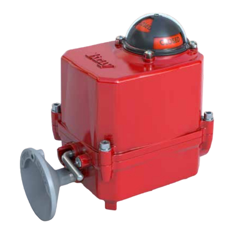
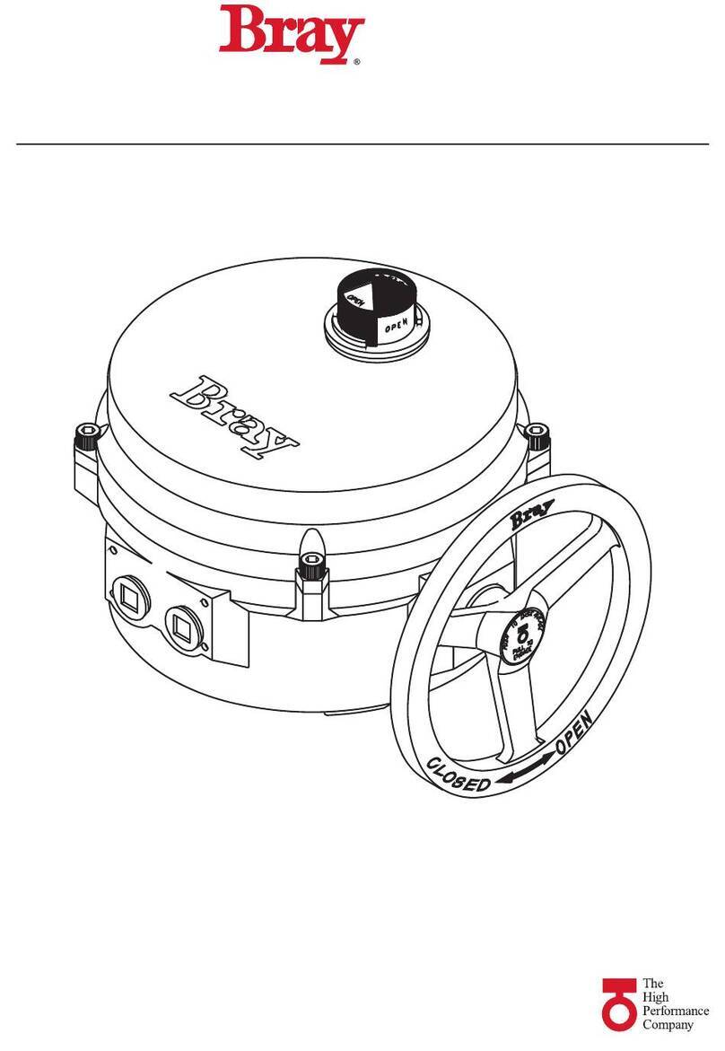
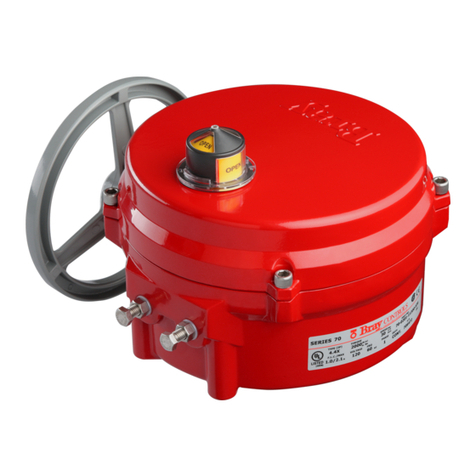
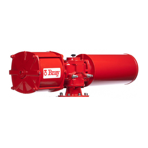
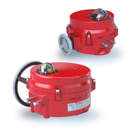
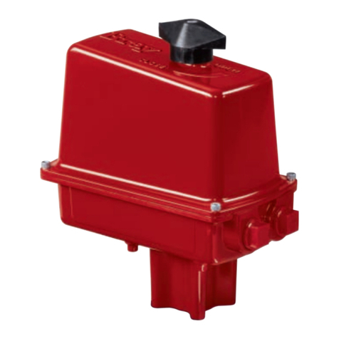
Bray Series 70 User manual

Series 70
2nd Generation Electric Actuator
Operation and Maintenance Manual
Your Global Flow Control Partner™


1
Series 70 Electric Actuator
Operation and Maintenance Manual
FOR MORE INFORMATION ON THIS PRODUCT AND OTHER BRAY PRODUCTS
PLEASE VISIT OUR WEBSITE – www.bray.com
Table of Contents
Safety Instructions - Definition of Terms . . . . . . . . . . . . . . . . . . . . . . . . . . . . . . . .2
Hazard-Free Use. . . . . . . . . . . . . . . . . . . . . . . . . . . . . . . . . . . . . . . . . . . .2
Qualified Personnel . . . . . . . . . . . . . . . . . . . . . . . . . . . . . . . . . . . . . . . . . .2
Part Numbering System Reference Chart . . . . . . . . . . . . . . . . . . . . . . . . . . . . . . .3
Introduction. . . . . . . . . . . . . . . . . . . . . . . . . . . . . . . . . . . . . . . . . . . . . .3
Principle of Operation . . . . . . . . . . . . . . . . . . . . . . . . . . . . . . . . . . . . . . .3
Electrical Operation. . . . . . . . . . . . . . . . . . . . . . . . . . . . . . . . . . . . . . . . .3
General Electrical Schematic . . . . . . . . . . . . . . . . . . . . . . . . . . . . . . . . . . . .3
Mechanical Operation . . . . . . . . . . . . . . . . . . . . . . . . . . . . . . . . . . . . . . .3
Manual Override Operation (Declutchable) . . . . . . . . . . . . . . . . . . . . . . . . . . . . .4
Pre-Installation Storage . . . . . . . . . . . . . . . . . . . . . . . . . . . . . . . . . . . . . . .4
Installation . . . . . . . . . . . . . . . . . . . . . . . . . . . . . . . . . . . . . . . . . . . . . .4
Mounting to a Valve . . . . . . . . . . . . . . . . . . . . . . . . . . . . . . . . . . . . . . . .4
Field Wiring . . . . . . . . . . . . . . . . . . . . . . . . . . . . . . . . . . . . . . . . . . . .4
Multiple Actuator (Parallel) Wiring . . . . . . . . . . . . . . . . . . . . . . . . . . . . . . . . .5
Actuator Diagram without I.R.B. . . . . . . . . . . . . . . . . . . . . . . . . . . . . . . . . . .5
Travel Limit Switch and Mechanical Travel Stop Adjustment. . . . . . . . . . . . . . . . . . . . .5
S70 On/Off Actuator with Interposing Relay Board (I.R.B.) . . . . . . . . . . . . . . . . . . . . .5
Close Travel Switch Adjustment . . . . . . . . . . . . . . . . . . . . . . . . . . . . . . . . . .6
Open Travel Switch Adjustment . . . . . . . . . . . . . . . . . . . . . . . . . . . . . . . . . .6
Disassembly and Assembly . . . . . . . . . . . . . . . . . . . . . . . . . . . . . . . . . . . . . .7
Procedure . . . . . . . . . . . . . . . . . . . . . . . . . . . . . . . . . . . . . . . . . . . . .7
Field or Factory Installable Options . . . . . . . . . . . . . . . . . . . . . . . . . . . . . . . . . .8
Torque Switches . . . . . . . . . . . . . . . . . . . . . . . . . . . . . . . . . . . . . . . . . .8
Torque Switch Mechanism . . . . . . . . . . . . . . . . . . . . . . . . . . . . . . . . . . . . .8
Heater . . . . . . . . . . . . . . . . . . . . . . . . . . . . . . . . . . . . . . . . . . . . . . .9
Installation Procedure . . . . . . . . . . . . . . . . . . . . . . . . . . . . . . . . . . . . . .9
Servo-Pro Module . . . . . . . . . . . . . . . . . . . . . . . . . . . . . . . . . . . . . . . . .9
Installation Procedure . . . . . . . . . . . . . . . . . . . . . . . . . . . . . . . . . . . . . 10
Servo Calibration . . . . . . . . . . . . . . . . . . . . . . . . . . . . . . . . . . . . . . . 10
External Signal Feedback Potentiometer . . . . . . . . . . . . . . . . . . . . . . . . . . . . . 11
Installation Procedure . . . . . . . . . . . . . . . . . . . . . . . . . . . . . . . . . . . . . 11
Set the Potentiometer . . . . . . . . . . . . . . . . . . . . . . . . . . . . . . . . . . . . . 11
Auxiliary Switches . . . . . . . . . . . . . . . . . . . . . . . . . . . . . . . . . . . . . . . . 11
Installation Procedure . . . . . . . . . . . . . . . . . . . . . . . . . . . . . . . . . . . . . 11
Auxiliary Switch Configuration Chart . . . . . . . . . . . . . . . . . . . . . . . . . . . . . . .12
Typical Wiring Diagram: On/Off Service . . . . . . . . . . . . . . . . . . . . . . . . . . . . . .13
Typical Wiring Diagram: Modulating Service . . . . . . . . . . . . . . . . . . . . . . . . . . . 14
Adjustments, Calibration and Status LED of Servo Pro . . . . . . . . . . . . . . . . . . . . . . 15
Status LED . . . . . . . . . . . . . . . . . . . . . . . . . . . . . . . . . . . . . . . . . . . . 15
Receptacles (Quick Connectors) . . . . . . . . . . . . . . . . . . . . . . . . . . . . . . . . . 16
Spinner. . . . . . . . . . . . . . . . . . . . . . . . . . . . . . . . . . . . . . . . . . . . . .17
Local Control Station (Single Phase Powered Actuators) . . . . . . . . . . . . . . . . . . . . . 17
Appendix A . . . . . . . . . . . . . . . . . . . . . . . . . . . . . . . . . . . . . . . . . . . . . 18
Basic Tools . . . . . . . . . . . . . . . . . . . . . . . . . . . . . . . . . . . . . . . . . . . . 18
Appendix B . . . . . . . . . . . . . . . . . . . . . . . . . . . . . . . . . . . . . . . . . . . . . 19
Actuator Troubleshooting Chart . . . . . . . . . . . . . . . . . . . . . . . . . . . . . . . . . 19
S70 Servo Pro Troubleshooting Chart . . . . . . . . . . . . . . . . . . . . . . . . . . . . . . 20
Appendix C - Exploded Views . . . . . . . . . . . . . . . . . . . . . . . . . . . . . . . . . . . .21
Series 70 - Housing Size 6 . . . . . . . . . . . . . . . . . . . . . . . . . . . . . . . . . . . . 21
Series 70 - Housing Size 12. . . . . . . . . . . . . . . . . . . . . . . . . . . . . . . . . . . .22
Series 70 - Housing Size 30. . . . . . . . . . . . . . . . . . . . . . . . . . . . . . . . . . . .23
Series 70 - Housing Size 180 for 3:1 Gear Box . . . . . . . . . . . . . . . . . . . . . . . . . . 24
Series 70 - 3:1 Gear Box . . . . . . . . . . . . . . . . . . . . . . . . . . . . . . . . . . . . . 25

2
Series 70 Electric Actuator
Operation and Maintenance Manual
Hazard-Free Use
This device left the factory in proper condition to be
safely installed and operated in a hazard-free manner.
The notes and warnings in this document must be
observed by the user if this safe condition is to be
maintained and hazard-free operation of the device
assured.
Take all necessary precautions to prevent damage to the
actuator due to rough handling, impact, or improper
storage. Do not use abrasive compounds to clean the
actuator, or scrape metal surfaces with any objects.
The control systems in which the actuator is installed
must have proper safeguards to prevent injury to
personnel, or damage to equipment, should failure
of system components occur.
Qualified Personnel
• A qualified person in terms of this document is one
who is familiar with the installation, commissioning
and operation of the device and who has appropriate
qualifications, such as:
• Is trained in the operation and maintenance of
electric equipment and systems in accordance with
established safety practices
• Is trained or authorized to energize, de-energize,
ground, tag and lock electrical circuits and equipment
in accordance with established safety practices
• Is trained in the proper use and care of personal
protective equipment (PPE) in accordance with
established safety practices
• Is trained in first aid
• In cases where the device is installed in a potentially
explosive (hazardous) location – is trained in
the operation, commissioning, operation and
maintenance of equipment in hazardous locations
!
WARNING
The actuator must only be installed, commissioned,
operated and repaired by qualified personnel.
The device generates large mechanical force during
normal operation.
All installation, commissioning, operation and
maintenance must be performed under strict
observation of all applicable codes, standards and
safety regulations.
Reference is specifically made here to observe all
applicable safety regulations for actuators installed in
potentially explosive (hazardous) locations.
Safety Instructions - Definition of Terms
READ AND FOLLOW THESE INSTRUCTIONS
SAVE THESE INSTRUCTIONS
WARNING indicates a potentially hazardous situation which, if not avoided, could
result in death or serious injury.
CAUTION indicates a potentially hazardous situation which, if not avoided, may result
in minor or moderate injury.
!
NOTICE
used without the safety alert symbol indicates a potential situation which, if
not avoided, may result in an undesirable result or state, including property
damage.
!
!

3
Series 70 Electric Actuator
Operation and Maintenance Manual
Introduction
The Bray Series 70 is a quarter turn electric actuator
with manual override for use on any quarter turn valve
requiring up to 18000 in.lb of torque. Operating speeds
vary between 6 to 110 seconds.
Principle of Operation
The Series 70 actuator is divided into two internal
sections; the power center below the switchplate,
and the control center above the switchplate. Below
the switchplate the capacitor and gearmotor with its
spur geartrain drive a non-backdriveable worm gear
output. The override mechanism for manual operation
is also housed here. Above the switchplate is where
user required, readily accessible components are placed.
The camshaft assembly, limit switches, terminal strips,
torque switches, heater, and servo are all placed here
for easy access. External to the unit are adjustable
mechanical travel stops, a large easy to read indicator,
the unique manual override handwheel and dual
conduit entry ports. The external coating is a high
quality polyester powder coat which has exceptional
UV as well as chemical resistance.
Electrical Operation
The motors used in the Bray Series 70 are either
permanent induction split capacitor design (single
phase AC power), SCI (Three Phase AC Power) or PM
(DC Power). Travel limit switches are mechanical form
(SPDT) with contacts rated at 10 amp (0.8 PF), 1/2 HP
125/250 VAC. In cases where the torque capacity of
the unit is exceeded to the point where the motor stalls
and overheats, a thermal protector switch built into the
motor windings will automatically disconnect the motor
power. Once the motor cools sufficiently the thermal
protector switch will reset. Optional torque switches are
available in all units to prevent the possibility of stalling
the motor, thus reducing the necessity for an inoperable
thermal cooldown period. Torque switches installed by
Bray are factory adjusted to the output torque rating
of the unit using electronic torque testing equipment.
!
NOTICE
Torque switches are not field adjustable. Adjustment
of torque switches in the field will void warranty.
General Electrical Schematic
NEUTRAL
LIVE
OPEN
CLOSE
DOUBLE
OVERRIDE
SWITCHES
THERMAL PROTECTOR
OPEN
CLOSE
CAPACITOR
TORQUE
SWITCHES
(OPTIONAL)
TRAVEL
LIMIT
SWITCHES
SINGLE
PHASE
POWER
SUPPLY
FIELD WIRING
COM
N.C.
N.O.
CAMS
MOTOR
COM
N.C.
N.O.
COM
N.C.
N.O.
COM
N.C.
N.O.
COM
N.C.
N.O.
COM
N.C.
N.O.
1
2
3
NOTE: this is only a reference. For the actual wiring diagram refer
to the diagram placed inside the actuator cover.
Mechanical Operation
Mechanically, the ratio of the gearmotor determines the
speed of the unit. The gearmotor utilizes high efficiency
spur gears with various ratios for the different speeds.
Initial gear reduction through the spur gears is then
transferred to the worm shaft. The final gear reduction
and output is through a non-backdriveable worm gear
set. Positioning is determined by an indicator-cam
shaft linked to the output shaft. In the declutchable
condition the manual override drives the worm shaft
when engaged.
Part Numbering System Reference Chart
SerieS Torque Code Speed produCT STyle VolTage Trim
70 AAA X 113 Y Z 536
HouSing
Size parT number Torque
(In.Lbs)
Speed, ¼Turn
(Seconds)
Supply
(Z Voltage)
6 70-003X-113YZ-536 300 30/15 0/2/4
6 70-006X-113YZ-536 600 30 0/3/4
12 70-008X-113YZ-536 800 30/15/6 0/4/8
12 70-012X-113YZ-536 1200 30/15/6 0/4/9
12 70-020X-113YZ-536 2000 30/15 0/2/3/4/5/6/7/8
30 70-030X-113YZ-536 3000 30/18 0/2/4/5/6/7/8
30 70-050X-113YZ-536 5000 30/18 0/2/3/4/5/6/7/8
30 70-065X-113YZ-536 6500 30 0/2/4/5/6/7/8
180 70-13WX-113YZ-536 13000 110 0/4
180 70-18WX-113YZ-536 18000 110 0/4
Use this chart as a guide to interpret the S70 electric actuator part number.
Note: Not all combinations are possible.
W - DESIGNATES THE OUTPUT BORE DIAMETER
02.5 Inches
11.97 Inches
X - DESIGNATES THE SPEED
X: 0 1 2 3 4 5 6
Sec: 60 30 15/18 10 6 8 110
Y - DESIGNATES STYLE
ABasic Unit - Declutchable
C24VAC Unit with 24VAC Servo
DWith Interposing Relay Board*
*Only available for 120VAC or 220VAC On/Off units
Z - DESIGNATES THE VOLTAGE
Z: 0123456789
Voltage:
120VAC
12VDC
24VDC
24VAC
220VAC
380V
3-PH
400V
3-PH
440V
3-PH
480V
3-PH
208V
3-PH

4
Series 70 Electric Actuator
Operation and Maintenance Manual
Manual Override Operation (Declutch-
able)
The manual override operates similar to a watch
adjusting knob. To engage the manual override, simply
pull the handwheel to its outermost position. A yellow
stripe is revealed for visual indication that the unit
cannot run electrically. The two handwheel positions,
engaged and disengaged, are held in place with the use
of spring plungers. The handwheel remains in position
until physically moved. Rotating the handwheel in the
clockwise direction will rotate the output shaft in the
same clockwise (closed) direction and vice-versa.
!
CAUTION
A label on the handwheel hub warns users not to
exceed a specific rim pull force, for each size of
actuator. If the rim pull force is exceeded, the roll pin
securing the handwheel onto the manual override
shaft is designed to shear, thus preventing more
serious internal gearing damage.
Pre-Installation Storage
Actuators are not weatherproof until properly installed
on the valve or prepared for storage. Bray cannot accept
responsibility for deterioration caused on-site once the
cover is removed.
!
NOTICE
Units are shipped with two metal screw-in plugs to
prevent foreign matter from entering the unit. To
prevent condensation from forming inside these
units, maintain a near constant external temperature
and store in a well-ventilated, clean, dry room away
from vibration.
For units with an internal heater, power should
be supplied to the heater via conduit entry and
appropriate sealing gland.
Store units on a shelf or wooden pallet in order to
protect against floor dampness.
Keep units covered to protect against dust and dirt.
Installation
Mounting to a Valve
All Bray Series 70 electric actuators are suitable for
direct mounting on Bray butterfly valves. With proper
mounting hardware, the S70 actuator can be installed
onto other quarter-turn valves or devices.
!
NOTICE
The standard mounting position for the actuator is to
orient the unit with its handwheel in a vertical plane
and parallel to the pipeline. If the actuator is to be
mounted on a vertical pipe, it is recommended that
the unit be positioned with the conduit entries on
the bottom to prevent condensation from entering
the actuator by way of the conduit. In all cases, the
conduit should be positioned to prevent drainage into
the actuator.
The actuator should be mounted to the valve as follows:
1. Manually operate the actuator until the output shaft
of the actuator is in line with the valve stem. If
possible, select an intermediate position (i.e. valve
disc/stem and actuator both half open).
2. Place the proper adapter, if required, onto the valve
stem. It is recommended that a small amount of
grease be applied to the adapter to ease assembly.
3. Mount the actuator onto the valve stem. It may be
necessary to swing or manually override the actuator
to align the bolt patterns.
4. Install the furnished mounting studs by threading
them all the way into the actuator base.
5. Fasten in place with the furnished hex nuts and
lock washers.
Field Wiring
!
WARNING
Turn off all power and lock out service panel before
installing or modifying any electrical wiring.
Each actuator is provided with two (2) conduit entries
(one for power and one for control).
1. The motor full load current is noted on the nameplate
of the actuator. The terminal strip will accept wire
sizes ranging from 14 to 22 AWG (14 to 24 AWG
for the servo).
!
NOTICE
18 AWG minimum wire is recommended for all field
wiring.
Note that the optional heaters use approximately 0.5
amps at 110 volts.
2. All actuators have their applicable wiring
diagram attached to the inside of the cover. Field
wiring should be terminated at the actuator terminal
strip in accordance with this wiring diagram.

5
Series 70 Electric Actuator
Operation and Maintenance Manual
The back feeding of one actuator by another one wired
in parallel is eliminated by using the I.R.B.
If actuator is running Open and customer switches
“instantaneously” to run Closed, the Open relay will
take time to ‘drop-out’ and the Close relay will take
time to ‘pull-in’ this time lapse is ~ 40ms. The time
delay provided by the I.R.B. will protect the switches
and gears from the controller’s instantaneous command
signal reversal.
Current draws and field wirings are not affected by
adding I.R.B.
S70 120VAC I.R.B., auxiliary switch, heater, and torque
switch option are UL certified units.
!
NOTICE
The conduit connections must be properly sealed to
maintain the weatherproof integrity of the actuator
enclosure.
Multiple Actuator (Parallel) Wiring
!
CAUTION
Do not connect more than one S70 actuator which
do not have I.R.B. installed to a single SPDT switch.
A voltage is present on the opposite winding to the
powered one. If this winding is connected to another
as shown in the INCORRECT diagram it will interfere
with the motor performance. Use a multiple pole
switch as shown in the CORRECT diagram.
Actuator Diagram without I.R.B.
!
CAUTION
Do not reverse motor instantaneously when it is still
running. Reversing direction to actuator motor when
it is running can cause damage to motor, switches and
gearing. Directional control switching can be done by
PLC in 20ms or by a small relay in 46ms. Therefore time
delay of 1s has to be incorporated into the control
scheme to avoid damage.
Travel Limit Switch and Mechanical
Travel Stop Adjustment
!
CAUTION
The electrical travel switches must be set to activate
(depress) prior to reaching the mechanical travel
stops. The cams are color coded (green for open, red
for closed).
NOTE: Manual travel stops are designed to prevent
manual overtravel from turning the handwheel, not
to stop the electric motor. The travel stops have an
adjustment range of approximately 10-degrees.
S70 On/Off Actuator with Interposing Relay Board (I.R.B.)

6
Series 70 Electric Actuator
Operation and Maintenance Manual
Close Travel Switch Adjustment
1. Loosen the mechanical stop for the closed position
and back it off so that it does not interfere with
actuator travel (closed stop located on right when
viewed from travel stop side of actuator).
2. Remove the indicator rotor by pulling up it straight
up away from the indicator shaft. This will expose
the machined groove on the end of the cam shaft,
which is the reference to the valve disc position.
NOTE: For Housing Size 180, ignore steps 2 and 6. The
valve position indicator plate on the lower gearbox is
the reference to the valve position.
3. Manually operate the actuator handwheel clockwise
until the valve reaches the desired fully closed
position.
4. Rotate the red adjusting knob by hand or with a flat
head screwdriver until the cam lobe just activates
(depresses) the switch from a clockwise direction.
NOTICE: All continuous duty actuators have a cam
locking screw. Cam locking screw must be slackened
before cam adjustments and re-tightened after cam
adjustments.
NOTE: It is possible that the rotation of one cam will
move the other cam. If this occurs, hold the other
knobs or cams during adjustment.
UPPER GREEN
“OPEN” CAM
LOWER RED
“CLOSE” CAM
POT DRIVE GEAR
“BLACK” NOT SHOWN
FOR CLARITY REASONS
CAM ADJUSTMENT KNOB
(ONLY ADJUST IF LOCKING
SCREW IS SLACKENED)
CAM
LOCKING
SCREW
5. With the travel switch in the closed position, rotate
the handwheel clockwise ½ turn for Housing Size
6, 1 turn for Housing Size 12, ½ turn for Housing
Size 30, and 2 turns for Housing Size180. Adjust the
closed travel stop bolt until it bottoms against the
output gear and lock it in position with the locknut.
6. After all travel switch adjustments have been
completed, replace the indicator rotor and secure
the actuator cover.
Open Travel Switch Adjustment
1. Loosen the mechanical stop for the open position
and back it off, so that it does not interfere with
actuator travel. The open stop is located on the
left, when viewed from travel stop side of actuator.
2. Remove the indicator rotor by pulling it straight
up away from the indicator shaft. This will expose
the machined groove on the end of the cam shaft,
which is the reference to the valve disc position.
NOTE: For Housing Size180, ignore steps 2 and 6. The
valve position indicator plate on the lower gearbox is
the reference to the valve position.
3. Manually operate the actuator handwheel
counterclockwise until the valve reaches the desired
open position.
4. Rotate the green adjusting knob until the cam
lobe just activates (depresses) the switch from a
counterclockwise direction.
NOTICE: All continuous duty actuators have a cam
locking screw. Cam locking screw must be slackened
before cam adjustments and re-rightened after cam
adjustments.
NOTE: It is possible that the rotation of one cam will
move the other cam. If this occurs, hold the other
knobs or cams during adjustment.
5. With the travel switch in the open position, rotate
the handwheel counterclockwise ½ turn for Housing
Size 6, 1 turn for Housing Size 12, ½ turn for Housing
Size 30, and 2 turns for Housing Size 180. Adjust
the open travel stop bolt until it bottoms against the
output gear and lock in position with the locknut.
6. After all travel stop adjustments have been
completed, replace indicator rotor and secure the
actuator cover.

7
Series 70 Electric Actuator
Operation and Maintenance Manual
Disassembly and Assembly
Tools required:
See Appendix A for a complete list of basic tools.
NOTE 1: Assembly is the opposite of removal.
NOTE 2: Pictures shown for Housing Size 6 are typical
for all sizes.
Procedure
!
WARNING
Turn off all power and lock out service panel before
installing or modifying any electrical wiring.
1. Disconnect motor wires from the main terminal strip
(motor neutral, open, and close).
2. Remove the switchplate by unscrewing the seven
Phillips head mounting screws. The switchplate
should lift out as an assembly with the camshaft
attached.
3. The switchplate can be independently disassembled.
4. To remove the Gearmotor, first disconnect the motor
leads which run to the capacitor, and unscrew the
mounting screws for Housing Size 6 (two lower,
one upper) for other Housing Sizes (four lower, one
upper). The motor can now be removed vertically out
of the unit. Note: do not misplace the alignment pin.
5. To remove the worm shaft spur gear, remove the
spring pin using a 3/32” punch, then slide the gear
off the end of the worm shaft for Housing Sizes 6
and 12. Remove bowed E-clip retainer for Housing
Size 30-180.
6. To remove the output drive worm gear, back off
both mechanical travel stops. Remove the retaining
ring and thrust washer, then lift the output drive
worm gear out of its base.
7. The handwheel is held by a spring pin.
!
CAUTION
Further disassembly of the unit requires special tools
and procedures, and thus will not be covered in this
manual.

8
Series 70 Electric Actuator
Operation and Maintenance Manual
Field or Factory Installable Options
Torque Switches
Torque switches are a factory installed and calibrated
option available for all Series 70 units. Installation is
simple, but due to the requirement for special calibration
equipment, it is not recommended for field installation.
In fact, modifying the factory torque setting voids
the actuator warranty. Removal of the switchplate
invalidates factory calibration
The unique mechanism is extremely accurate and has
excellent repeatability. The worm is pinned to the worm
shaft, which is held in position with a stack of disc
springs at both ends. The torque transmitted through
the worm to the output worm gear acts directly against
the disc springs, which compress proportionately. The
worm and worm shaft shift longitudinally as a result.
A specially designed drive lever and pin is incorporated
into the worm, providing the profile for the torque
switching mechanism. A drive lever & pin rides in the
worm gear torque sensor groove, and in turn drives
a cam. The cam then actuates its electrical switch,
which interrupts the power to the motor winding when
the torque exceeds the setting. The motor can still be
powered to run in the opposite direction, the switch
will release automatically.
Switching Mechanism
Torque Switch Mechanism

9
Series 70 Electric Actuator
Operation and Maintenance Manual
Heater
To prevent condensation from forming inside the
actuator, Bray offers an optional heater. The heater is
a PTC (Positive Temperature Coefficient) style which
has a unique temperature - resistance characteristic.
The heater self-regulates by increasing its electrical
resistance relative to its temperature. The heater does
not require external thermostats or switches to control
its heat output. It is constructed of a polycrystalline
ceramic, sandwiched between two conductors, and
wrapped inside a thermally conductive electrical
insulator.
Connect the heater wires to the terminal strip as
indicated on the wiring diagram.
NOTE: The heater must have a constant power supply
to be effective.
!
WARNING
The heater surface can reach temperatures in excess
of 200 degrees Celsius
Heater Kit Consists of:
1. Heater with flying leads
2. Heater Mounting Bracket
3. #10 pan head screw, Phillips drive
Tools required:
• For terminal wiring: Screwdriver, 3/16” tip flat blade
• For heater mounting screw: Screwdriver, No.1 Phillips
Installation Procedure
The heater is mounted through a hole provided in
the switchplate.
Before servicing unit, switch all power off at the service
panel and lock the service disconnecting means to
prevent power from being switched on accidentally.
When the service disconnecting means cannot be
locked, securely fasten a prominent warning device,
such as a tag, to the service panel.
Disconnect all power to the unit.
1. Place the heater snugly into its mounting bracket
until approx. 1/2 to 1” is left above the bracket as
shown in diagram.
2. Slip the heater into its mounting hole.
3. Align the fastening hole in the bracket with the
threaded screw hole in the plate. Fasten the heater
to the switchplate.
4. Connect the heater wires to the terminal strip as
indicated on the wiring diagram.
Servo-Pro Module
Servo kits can be field installed on any continuous
duty actuator (30, 60, or 110 sec. operation speed) to
provide proportional positioning in response to a control
signal. Intermittent duty actuators are not adaptable
for servo control.
Servo Kit Consists of:
1. One servo module
2. Four #6 cross drive pan head screw (two for servo,
two for feedback potentiometer)
3. One potentiometer assembly
4. Two #6 type A internal lockwashers (for pot)
5. One wiring diagram sticker for attaching to inside
of actuator’s cover
6. One wiring diagram sticker for servo units with
torque switches
Tools required:
• For actuator terminals wiring Screwdriver, 3/16”
flatblade
• For servo terminals: Screwdriver, No.1 Phillips
• For servo and pot mounting screws: Screwdriver, No.2
Phillips

10
Series 70 Electric Actuator
Operation and Maintenance Manual
Installation Procedure
• Disconnect all power to the unit.
• Remove the on/off duty, 9 point terminal strip and
its marker.
1. Disconnect all wiring to the terminal strip.
2. All wiring in the actuator is color coded to facilitate
wiring, and does not need to be tagged or marked.
3. Field wiring should be marked if it is not already
color coded.
Mount the servo module
4. Secure the servo card module onto switchplate with
the 2X #6 screws.
Install the potentiometer assembly
5. The potentiometer installs next to the camshaft
where there are two threaded holes provided.
6. The potentiometer assembly must be mounted in
the correct orientation, with the actuator in its fully
open (counter clockwise) position, the indicator shaft
should be in-line with raised green rib on pot gear.
7. Push the assembly towards the cam to mesh the pot
gears. Then tighten the mounting screws.
Note: On Housing Size 180, the raised green rib on
pot gear should be aligned with arrow on lower gear
box’s position indicator plate.
8.
Green Rib
Rotate the actuator handwheel so that the red cam
lobe is facing the body of the potentiometer. Make
sure that the cam is not touching the potentiometer
assembly. Readjust the assembly position if necessary.
Wire the potentiometer to the servo
9. Connect the potentiometer wires into the terminal
strip on the servo module.
10.Wire according to the wiring diagram provided.
Wire the servo to the actuator
11.Wire according to the wiring diagram provided.
12.See the servo calibration instructions.
Servo Calibration
The calibration procedure defines the limits of operation
of the Series 70 Actuator between the fully open valve
position and the fully closed valve position. The cams
on the Series 70 Actuator define the fully open and
closed positions of the valve and may be set at any
degree of opening. The only requirement is that the
open cam limit setting must set at a higher degree of
opening than the closed cam limit setting. In other
words, the “Open” position must be more open than
the “Closed” position.
Calibration is performed as follows:
1. Adjust the Open and Closed limit switch cams on
the Series 70 Actuator to the desired position.
2. Engage the handwheel and move the Series 70
Actuator to its mid position.
NOTE: An analog signal source is not required
for calibration. Press and hold the “Calibrate” Set
pushbutton for a minimum of 2 seconds. When the
servo status LED begins to flag rapidly, release the
button. The servo will now seek both travel limits and
record these values to its nonvolatile memory. Following
a successful calibration, the status LED will begin to
flash a slow single green flash. If the calibration is
unsuccessful, the status LED will alternately flash red
and green. If this occurs, make sure the cams and the
potentiometer are set correctly.
This completes the “Self Calibration” procedure.
After completing the calibration procedure, it is
good practice to apply the fully closed and fully open
Command Signals, and verify that the S70 Actuator
moves to the proper positions.
* Refer to Servo Pro Version 3.0 Operation and
Maintenance Manual for more details
MOTOR
OPEN
1
ON
MOTOR
CLOSE
FUSE
NEUTRAL
NEUTRAL
LINE
Power
OUTPUT (+)
OUTPUT (-)
+5 VDC
INPUT (+)
INPUT (-)
OPEN
LIMIT
CLOSE
LIMIT
COMMON
COMMON
HANDWHEEL
CALIBRATE
STATUS
+5 VDC
COMMON
FB POT
HIGH
VOLTAGE
SERVO
210987
6543
PRO
HEATER
DEAD BAND
CLOSE
SPEED
OPEN
SPEED
CLOSE
OPEN
COMMON
TORQUE LIMIT
CLOSE
OPEN
COMMON
CONTROL BOX
S10
S9
S8
S7
S6
S5
S4
S3
S2
S1

11
Series 70 Electric Actuator
Operation and Maintenance Manual
External Signal Feedback
Potentiometer
Potentiometers for external feedback can be field
installed on all continuous duty actuators. Actuators
which are not continuous duty do not have a pot gear
fitted on their indicator shafts & must be fitted with
a new shaft which has a pot drive gear for feedback
pot (see Options: Auxiliary Switches).
Feedback Potentiometer Kit consists of:
• One potentiometer assembly
• Two #6 cross drive pan head screws
• Two #6 internal lockwashers
• One 4 point terminal strip
• One terminal strip marker for feedback pot
• One small wiring diagram sticker for the additional
potentiometer
Tools Required:
• For terminal wiring Screwdriver, 3/16” tip flat blade
• For pot mounting screws Screwdriver, No.2 Phillips
Installation Procedure
1. The potentiometer
installs next to the
camshaft where there
are two threaded holes
provided for it.
2. The potentiometer
assembly must be
mounted in the correct
orientation, with the
actuator in its fully open
(counter clockwise)
position, the indicator shaft should be in-line with
raised green rib on pot gear.
3. Push the assembly towards the cam to mesh the pot
gears. Then tighten the mounting screws.
4. Rotate the actuator handwheel so that the red cam
lobe is facing the body of the potentiometer. Make
sure that the cam is not touching the potentiometer
assembly. Readjust the assembly position if necessary.
5. Fit the 4 point terminal strip and marker in the kit.
Before laying down the marker, cut it to obtain a
marker as illustrated: opposite
6. Wire the pot to the terminal strip using the small
stick-on wiring diagram provided.
7. Adhere the wiring diagram sticker to the inside of
the cover.
Set the Potentiometer
1. Manually operate the actuator handwheel until the
unit is in the fully closed position.
2. Rotate theblack potentiometerdrive gearadjustment
knob, to engage the potentiometer gear at the
closed position.
3. Manually operate the actuator to the fully open
position.
Auxiliary Switches
Auxiliary switches are available, refer to chart on next
page.
NOTES:
1. All auxiliary switches have voltage-free contacts.
2. Housing Sizes 6, 12, and 30 have double lobe cams.
Housing Size 180 has single lobe cams.
3. Main limit switches are one OPEN and one CLOSE
switch.
4. Auxiliary switches are one OPEN and one CLOSE
switch, which are fixed to activate 3° before the
main switches.
5. Adjustable auxiliary switches are adjustable to any
position.
Installation Procedure
1. Cut terminal strip marker to length needed with
letters facing up.
2. Mount terminal strip and marker to switchplate using
two #4-40 screws.
Green Rib
178 9
2 3 4 5 6
D
C
B
A
Cut marker as needed
(4-way shown as example)
and mount to switchplate as shown.
Aux Terminal Strip

12
Series 70 Electric Actuator
Operation and Maintenance Manual
CONFIGURATION HOUSING
SIZE 6
HOUSING
SIZES 12 & 30
HOUSING
SIZE 180
1. ON/OFF (Intermittent Duty
Motor) with Main Switch-
es (Standard OPEN and
CLOSE switches)
2 Switch
2 Cams
Standard Assembly P/N
2 Switch
2 Cams
Standard Assembly P/N
N/A
2. ON/OFF (Continuous Duty
Motor) with Main Switch-
es (Standard OPEN and
CLOSE Switches
2 Switch
2 Cams
& Pot Gear
Standard Assembly P/N
2 Switch
2 Cams
& Pot Gear
Standard Assembly P/N
N/A
3. ON/OFF (Intermittent Duty
Motor) with Main and 1 set
of Auxiliary Switches
4 Switch
2 Cams
Kit PN/ 70-0006-22980-536
4 Switch
2 Cams
Kit PN/ 70-0012-22960-536
4 Switch
2 Cams
& Pot Gear
Standard
Assembly P/N
4. ON/OFF (Continuous Duty
Motor) with Main and 1 set
of Auxiliary Switches
4 Switch
2 Cams
& Pot Gear
Kit P/N 70-0006-22980-536
4 Switch
2 Cams
& Pot Gear
Kit P/N 70-0012-22960-536
4 Switch
2 Cams
& Pot Gear
Standard
Assembly P/N
5. ON/OFF with Main, 1 set of
Auxiliary, and 1 Adjustable
Auxiliary Switches
5 Switch
3 Cams
Kit P/N 70-0006-22983-536
5 Switch
3 Cams
Kit P/N 70-0012-22963-536
N/A
6. ON/OFF with Main, 1 set of
Auxiliary, and 1 set of Ad-
justable Auxiliary Switches
6 Switch
3 Cams
Kit P/N 70-0006-22984-536
6 Switch
3 Cams
Kit P/N 70-0012-22964-536
N/A
7. ON/OFF with Main, 1 set of
Auxiliary, and 2 adjustable
Auxiliary Switches
For use with control station
only. See Factory
6 Switch
4 Cams
Kit P/N 70-0012-22961-536
6 Switch
4 Cams
& Pot Gear
8. ON/OFF with Main, 1 set
of Auxiliary, and 2 sets
of adjustable Auxiliary
Switches
N/A
8 Switch
4 Cams
Kit P/N 70-0012-22962-536
N/A
9. Servo with Main, 1 set of
Auxiliary, and 1 adjustable
Auxiliary Switches
N/A
5 Switch
3 Cams & 1 Pot Gear
Kit P/N 70-0012-22966-536
5 Switch
3 Cams & 1 Pot
Gear
10. Servo with Main, 1 set of
Auxiliary, and 2 Adjust-
able Auxiliary Switches
N/A N/A
6 Switch
4 Cams
& Pot Gear
11. ON/OFF with Main and
1 Adjustable Auxiliary
Switch
3 Switches
3 Cams
Kit P/N 70-0006-22988-536
3 Switch
3 Cams
Kit P/N 70-0012-22968-536
N/A
12. Servo with Main and
1 Adjustable Auxiliary
Switch
N/A
3 Switch
3 Cams & 1 Pot Gear
Kit P/N 70-0012-22971-536
N/A
Auxiliary Switch Configuration Chart

13
Series 70 Electric Actuator
Operation and Maintenance Manual
Wiring diagram for basic unit with Form-C (SPDT) travel limit switches, I.R.B., and double override switches.
(Drawn for actuator in its fully closed condition.)
Wiring diagram for unit with Form-C (SPDT) travel limit switches, “Voltage Free” Auxiliary open/close
switches, I.R.B., double override switches and torque switches.
(Drawn for actuator in its fully closed condition.)
Actuator Form-C Switches, SPDT
Housing Size: 6
V3-Sw
Housing Size:12, 30 & 180
V3-Sw with Lever
Typical Wiring Diagram: On/Off Service
N.C.
N.O.
COM.
N.C.
N.O.
COM.

14
Series 70 Electric Actuator
Operation and Maintenance Manual
SWITCH COMMAND INPUT
4-20 mA DC 0-5 VDC * 0-10 VDC 2-10 VDC
1Off On On On
2Off Off On On
3Off Off Off On
Output
4-20 mA DC 0-5 VDC 0-10 VDC 2-10 VDC
4Off On On N/A
5 On Off Off N/A
6Off On Off N/A
Forward Acting Reverse Acting
7Off On
Fail in Last Position Fail Enable **
8Off On
Fail Close Fail Open
9Off On
Torque Torque
Switch Enable Switch Disable
10 Off On
*To control servo with a remote potentiometer, set the Command Input to 0-5VDC (see Command Signal
Connector section; page 8 Servo Pro Manual).
**Fail position is the position that the servo will travel to when the control signal is removed. It does not
apply to 0-5VDC or 0-10VDC Command Signals.
Typical Wiring Diagram: Modulating Service
Wiring diagram for unit with Form-C (SPDT) travel limit switches, “Voltage Free” Auxiliary open/close
switches, Servo and double override switches. (Drawn for actuator in its full closed position.)
Warning: Turn ALL Power Off prior to adjusting DIP switches.

15
Series 70 Electric Actuator
Operation and Maintenance Manual
A. Adjust the open and close speed of your
actuator (The fastest closing speed of your
actuator is printed on the label of the unit):
1. Use the Close Speed trim pot to adjust the closing
speed of your actuator (pot in the fully CCW position
equals fastest close speed).
2. Use the Open Speed trim pot to adjust the opening
speed of your actuator (pot in the fully CCW position
equals fastest open speed).
B. Calibrate the Servo:
1. Manually position your actuator somewhere in mid
position; away from the travel limits.
2. Disengage your handwheel (push it back in towards
the actuator), hold down the Calibration push button
for two seconds and release, the servo will begin to
drive the actuator in the close direction and then
in the open direction in order to save these limits
to memory.
3. Following a successful calibration the servo’s Status
LED will begin to flash the normal operation code, an
unsuccessful calibration will yield a Red-Green-Red-
Green flash immediately following the attempted
calibration (for more information on the Status LED
flash codes see the Status LED Flash Code Table).
Table 2: Status LED Flash Codes
Green Status LED warning and information Flash Codes:
# Indication Reason Solution
1 Steady Green Flash Normal Operation Servo Functioning Ok
2 2 Green Flashes Calibration Defaults Loaded Adjust travel limits, push autocalibration PB
3 3 Green Flashes Reverse Acting Mode If you would like your servo to not operate in reverse
acting mode, set DIP switch 7 accordingly
4 4 Green Flashes 2-10VDC Input Command
Signal Selected
If you require a different configuration, set DIP
switches 1, 2, and 3 accordingly
5 1 Red Flashes Handwheel engaged Push the Handwheel in towards the actuator
6 2 Red Flashes Command Signal Failure Set DIP switches accordingly, send servo appropriate
signal
7 3 Red Flashes Feedback Pot Fault Position the feedback Pot correctly, see Feedback Pot
calibration
8 4 Red Flashes Limit Switch Fault Check wiring of limit switches, ensure that both
switches are not tripped simultaneously
9 5 Red Flashes Torque Switch Fault
Ensure that DIP switch 10 is positioned correct,
check wiring of torque switches, reverse direction of
actuator, correct over torque condition
10 6 Red Flashes Feedback Pot Wired In Reverse Correctly wire the Feedback Pot
Note: A flashing green LED provides status and warning information. The servo will operate normally in this state.
Some flash codes indicate a warning, where the servo has recovered automatically such as the detection of an invalid
calibration. In this case, a default calibration is automatically loaded that will allow the Servo to operate, but may not
be a perfect match to the actuator. The servo should be re-calibrated as soon as possible.
Adjustments, Calibration and Status LED of Servo Pro
Status LED
The “Status LED” is a bi-color LED which provides detailed information regarding the operation of the S70 Servo
Pro. Table 2 below illustrates the different combinations of LED flash codes and their corresponding conditions.
Following the table is a more descriptive explanation of the Flash Code. Whenever the LED is flashing green,
regardless of the flash code, the servo will operate, but not necessarily optimally. Whenever the LED flash codes
are RED, the servo will not operate. An example is an engaged handwheel, the Status LED will flash a single
red flash code and will not operate.

16
Series 70 Electric Actuator
Operation and Maintenance Manual
Receptacles (Quick Connectors)
Unless otherwise specified, power receptacles will be
5-pin mini style standard duty with a black anodized
aluminum finish. They conform to ANSI B93.55M except
in wire color. Euro receptacles will be used for low power
instrument and signal cable since they can be supplied
shielded. Wiring diagrams for plug-in receptacles for
either the Bray Series 70 or the local control station will
be provided as a separate diagram. Units ordered with
pin connector receptacles factory installed are wired
and tested. Cordsets which fit these receptacles may
be ordered in several lengths.
Receptacle Kit consists of:
1. Receptacle(s), male pin and male thread 1/2”-NPT,
in the quantity, style, and number of pins ordered
2. Reducing bushing 3/4” to 1/2” NPT for installation
in Housing Sizes 12 - 180 and control stations
3. Wiring diagram (SK-# below)
Tools required:
• For terminal wiring: Screwdriver, 3/16” tip flat blade
• For Mini or Euro receptacle: Wrench, 1”
Installation procedure:
1. Screw the receptacle into the actuator conduit entry
using Teflon tape or similar.
2. Wire to the terminal strip according to the wiring
diagram or the field wiring requirements.
Custom configurations are possible - consult the factory.
1L.C.S.: Local Control Station , WHICH implies mounted
to the actuator
2Travel indication is wired to the supply voltage
3Travel indication wiring is voltage free
4A 6-pinEURO connectoris requiredfor thisapplication,
consult factory for price and availability.
5 The Local Control Station comes standard with 120
Volt lamp bulbs, for other voltages consult factory.
Note: the Control Station lights must be wired to the
same voltage as the remote end of travel indication.
Euro receptacles use 22 AWG wire rated at 250V, 4 Amp.
Pin configuration interfaces with European standards.
Mini receptacles use 18 AWG wire rated at 300 V, 9
Amp. Pin configuration conforms to ANSI B93.55M.
* For requirements beyond these ratings consult
the factory.
Wiring Schematic for Optional Pin Connector Receptacles

17
Series 70 Electric Actuator
Operation and Maintenance Manual
Spinner
A spinner is available to ease and speed the manual
override ofthe BraySeries 70actuator. TheHousing Size6
units mount the spinner on a lever which screws onto the
back of the handwheel. The Housing Size 12-180 units
mount thespinneron therimof thehandwheel.Notethat
care should be exercised in the use of spinner equipped
handwheels. Rapid operation of the handwheel to close
the valve may cause water hammer. Also, rapid travel
into a travel stop may cause damage.
Spinner Kit Consists of:
For Housing Size 6 For Housing Sizes 12-180
Spinner and lever
assembly Spinner handle
Flat head socket cap
screw, #10-32UNF x 3/8
Socket head shoulder bolt,
1/4-20UNC x .75
Tools required:
• For socket head shoulder bolt and flat head capscrew
• Hex key, 1/8” for Housing Size 6
• Hex key, 3/16” for Housing Sizes 12-180
Installation procedure:
For Housing Size 6 units simply position the lever onto
the back of the handwheel then screw the flat head
cap screw in to place from behind.
For Housing Size 12-180 units, put the socket head
shoulder bolt through the spinner handle and screw
it firmly into the handwheel rim.
Local Control Station (Single Phase
Powered Actuators)
Bray’s local control station gives the user the ability to
locally override the actuator electrically. The station
is open / stop / close operation in the local control
mode. Red and green end of travel indication lights
are also provided. Depending on how it is wired the
control station can be used on the on - off units and
the servo controlled modulating units. Optional key
operated locking switches are available.
Note: The control station used with On - Off S70 and
that used with modulating S70 have different contact
blocks internally, the correct part number must be used
to ensure you order the correct unit (see price sheet).
Local Control Station Kit consists of:
1. Local control station assembly
2. Four socket head cap screws, #10-24UNC x 4.50
long, for mounting the station to the actuator
3. A gasket for sealing the station to the actuator
4. Wiring diagram
Tools required:
• For tapping control station mounting holes on
actuator, #10-24UNC Tap.
• For wiring Screwdriver, 3/16” flat blade.
• For mounting and cover screws Hex key, 5/32”
Installation procedure:
1. Tap #10-24UNC holes using the cored holes on the
side of actuator.
2. Adhere the gasket to the control box.
3. Mount the control box
to the actuator using
the 4 long socket head
capscrews.
4. Wire the control
box to the actuator
in accordance to
the wiring diagram
provided. The local
control station contains no terminal strips, and all
wiring is direct to the switches and lights via 2”
x 3/4” NPT holes
in bottom of
housing. Ordering
the control station
with optional
pin connector
receptacles will
eliminate the
necessity of field
wiring. The units
will be completely factory wired and tested.
Note: The inclined cover of the local control station can
be mounted in any of its four symmetrical positions.
If field wiring is required, first mount the base to the
actuator, then remove the cover to gain access for wiring.
*Local Control Station requires a dedicated set of
auxiliary switches for control station use only. Two
additional adjustable auxiliary switches are needed for
remote indication of open/close position in ON/OFF
configurations

18
Series 70 Electric Actuator
Operation and Maintenance Manual
Basic Tools
Common To All Units
Terminal connections, cam adjustment Screwdriver, 1⁄4" tip flat tip blade
All switches, terminal strip, torque switch plate Screwdriver, No.1 Phillips
Switchplate screws, capacitor Screwdriver, No. 2 Phillips
Servo trimmer pots Screwdriver, 1⁄8" flat tip for trim pots
Housing Size 6
Mounting nuts Wrench, 1⁄2"
Cover captivated capscrews Hex key, 1⁄4"
Travel stop adjusting bolts Wrench, 7⁄16"
Travel stop jam nuts Wrench, 7⁄16”
Motor mount socket flat head capscrew Hex key, 3⁄32"
Motor mount socket head capscrew Hex key, 9⁄64"
Conduit Entry Plug Hex key, 3⁄8”
Housing Size 12
Mounting nuts (small pattern) Wrench, 1⁄2”
Mounting nuts (large pattern) Wrench, 3⁄4"
Cover captivated capscrews Hex key, 5⁄16"
Travel stop adjusting bolts Wrench, 9⁄16"
Travel stop nuts Wrench, 9⁄16”
Motor mount socket head capscrew Hex key, 5⁄32"
Conduit Entry Plug Hex key, 9⁄16”
Housing Size 30
Mounting nuts, travel stop jam nuts Wrench, 3⁄4”
Cover captivated capscrews Hex key, 3⁄8"
Travel stop adjusting studs Wrench, 3⁄4”
Motor mount socket head shoulder bolt Hex key, 5⁄32”
Motor mount socket head cap screws Hex key, 3⁄16"
Conduit Entry Plug Hex key, 9⁄16”
Housing Size 180
Mounting nuts, travel stop jam nuts Wrench, 3⁄4”
Cover captivated capscrews Hex key, 3⁄8”
Travel stop adjusting studs Wrench, 5⁄16”
Motor mount socket head shoulder bolt Hex key, 5⁄32”
Motor mount socket head cap screws Hex key, 3⁄16”
Conduit Entry Plug Hex key, 9⁄16”
Appendix A
Other manuals for Series 70
9
Table of contents
Other Bray Controllers manuals
Bray
Bray Series 70 User manual

Bray
Bray Series 70 User manual
Bray
Bray 71 Seires User manual
Bray
Bray Series 70 User manual
Bray
Bray Series 70 User manual
Bray
Bray 92 Series User manual

Bray
Bray GAS Series User manual

Bray
Bray PA(M)24-27 Series User manual

Bray
Bray Series 70 User manual
Bray
Bray 75 Series User manual
