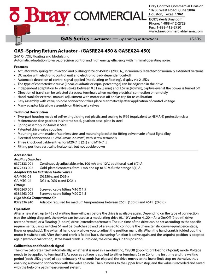
Bray PA(M)24-27 Series User manual

1
06/21/23
© 2022 Bray International, Inc.
Bray Commercial Division
13788 West Road, Suite 200A
Houston, Texas 77041
BCDSales@Bray.com
Phone: 1-888-412-2729
www.braycommercialdivision.com
PA(M)24-27 Series
IOM Manual
Safety Instructions . . . . . . . . . . . . . . . . . . . . . . . . . . . . . . . . . . . . . . . . . . . . . . . . . . . . . . . . . . . . . . . . 1
PA(M)24-27 Series Model Number Chart ............................................ 2
PA(M)24-27 Series Dimensions .................................................... 2
PA(M)24-27 Series Function. . . . . . . . . . . . . . . . . . . . . . . . . . . . . . . . . . . . . . . . . . . . . . . . . . . . . . . 2
PA(M)24-27 Series Mounting/Dial Settings . . . . . . . . . . . . . . . . . . . . . . . . . . . . . . . . . . . . . . . . . . 3
PA(M)24-27 Series Assembly . . . . . . . . . . . . . . . . . . . . . . . . . . . . . . . . . . . . . . . . . . . . . . . . . . . . . . 4
PA(M)24-27 Series Specifications .................................................. 5
PA(M)24-27 Series Wiring/DIP Switches ...........................................6,7
FOR MORE INFORMATION ON THIS PRODUCT AND OTHER BRAY PRODUCTS
PLEASE VISIT OUR WEBSITE – www.braycommercialdivision.com
Table of Contents
PA(M)24-27 Series - Installation, Operation and Maintenance Manual
Safety Instructions - Definition of Terms
Read, Follow and Save these instructions
WARNING
Indicates a potentially hazardous situation which, if not
avoided, could result in death or serious injury.
CAUTION
Indicates a potentially hazardous situation which, if not
avoided, may result in minor or moderate injury.
NOTICE
Used without the safety alert symbol indicates a potential situation
which, if not avoided, may result in an undesirable result or state,
including property damage.

2
PA24-27 Series - Installation, Operation & Maintenance Manual Continued
For Simple Set PIC Valves
Application
The PA(M) Series is a line of linear motor actuators to be used primarily
on Bray PIC Valves utilized in Building Automation Systems. These
actuators are available with a multitude of options for On/O/Floating or
Modulating with or without electronic Failsafe.
These actuators automatically calibrate to the stroke of the valve as soon
as power is applied and are field selectable direct or reverse acting.
A simple, reliable, versatile solution for your Bray Commercial Simple Set
pressure Independent control valves!
PA Series Actuators - Model Number Matrix
PA Series Actuators - Dimensions
PA Series Actuators - Function
PA24-27 24V On/O & Floating - Non-Fail Safe
PA24-27-FS 24V On/O & Floating - Fail Safe
PAM24-27 24V Modulating - Non-Fail Safe
PAM24-27-FS 24V Modulating - Fail Safe
4.09"
3.62"
2.08"
Unlike conventional control valve sizing where valves are sized to a Cv, the Simple Set valves are simply sized for flow and pipe
size. Refer to the ordering table for the wide range of flow values available.
IMPORTANT: Valve diameter should NEVER exceed pipe diameter!
The design of Simple Set combines high performance with small size and compact construction.
The main components of the valve are:
Actuator
Reacts to building controller
call for more or less flow.
Modulating Control Component
1. Rotates laterally to limit max flow
through the valve per the Pre-Setting
Scale
2. Moves vertically in response to the
actuator vcall for more or less flow.
P/T Plugs
Allows for measurement of
water flow and temperature.
Pressure Control Cartridge
Ensures constant flow rate is achieved under
fluctuating system pressures. As the system
dierential pressure increases and decreases,
the Dp controller absorbs and releases pressure
through an internal capillary tube maintaining
a constant Dp across the valve.
Pre-Setting Scale
Sets maximum flow
allowed through the valve.
Pre-Setting Scale (Detail)
3
5
4
1
2
4
3
2
1
0
5
.
5
m
m
3

3
PA24-27 Series - Installation, Operation & Maintenance Manual Continued
The PA24-27 Series Actuator combines an externally
adjustable automatic balancing valve with a full authority
modulating control valve.
The PA24-27 Series Actuator can be mounted in either the
supply or the return line.To avoid temperature extremes, it is
recommended on the return line. Installation of strainers and
isolation ball valves are recommended. The temperature in
and about the actuator should not be below 32˚F (0˚C).
Safety Instructions: The manufacturer is not liable for any damage resulting from use other than in the designated application.
Such risk lies entirely with the user. Observance of the mounting instructions is considered as part of the valve designated use.
180˚
180˚
1. The actuated valve installation should be easily accessible and provide sucient clearance for service and replacement.
2. Horizontal and vertical positions are preferred orientations for the installation of actuated valve. However, this actuator
can be installed at any in between angle.
Caution: Do not install at more than 90º from horizontal
PA Series Actuators - Mounting Instructions
PA Series Actuators - Dial Settings for 1/2" to 1-1/4"
PA Series Actuators - Mounting Orientations
INCORRECT MOUNTINGCORRECT MOUNTING

4
PA24-27 Series - Installation, Operation & Maintenance Manual Continued
1. Mount the valve adaptor to the valve and finger-tighten only.
Finger-tighten only. Do not use a wrench or any other tool.
2. Rotate knob clockwise to open the valve. Do not force knob in either
direction!
3. Manually adjust the knob to test piping network.
4. Once satisfied that the network is working properly, engage the actuator
over the valve adaptor and turn 30º clockwise (CW). You should hear an
audible click. To disengage the actuator, press the release button while
turning the actuator CCW 30˚.
Caution:
Actuator specifically calibrated to its adapter. DO NOT exchange original
adapter with a dierent actuator.
You must connect the actuator to its adaptor and mount it on a
valve before applying power. Failure to do so will result in incorrect
operation of the actuator.
Improper use of mechanical tools or application of excessive force
to tighten the adaptors on the valvescould lead to structural
damage of the adaptor, which could lead to failure over time.
If you plan to add foam insulation, do not add insulation foam be-
yond the chrome ring and around the adaptor. Improper installation
of insulation material could lead to a build-up of condensate water
around the valve and the chrome ring of the adaptor, which could
lead to a build-up of rust and compromise the structure of
the chrome ring that holds the adaptor.
Auto-Stroke Settings for Modulating (Analog) Models
Analog actuators perform an Auto-Stroke sequence upon every power-up. The Auto-Stroke sequence runs from 0 to the end
position and back in order to automatically detect the stroke limits and calibrate the input signal to the detected stroke limits.
The Auto-Stroke sequence can take up to a maximum of
2 minutes to complete.
During the Auto-Stroke sequence, the status LED remains on and the actuator will not perform any other action.
If the actuator and/or adaptor are removed from the valve after initial installation, an Auto-Stroke sequence
must be initiated must be initiated to recalibrate the actuator. To do so, remove and reapply the power.
PA Series Actuators - Assembly

5
PA24-27 Series - Installation, Operation & Maintenance Manual Continued
PA Series Actuators - Specifications
Technical Specifications - Actuators
Actuator Models
For Valves Sizes 1/2" to 1 -1/4"
PA24-27 PA24-27-FS PAM24-27 PAM24-27-FS
On/O & Floating Modulating
Non-Fail Safe Fail Safe Non-Fail Safe Fail Safe
Supply Voltage 22 to 26 AC/DC
Power
Consumption 5VA 10VA 5VA 10VA
Control Signal 2 Position On/O
or 3-Point Floating
Analog, 0-10VDC or 2-10VDC;
4-20mA with external
500Ω resistor
Input Impedance 4.7 K 10.0 K 100.0 K
Feedback Signal No 0-10VDC or 2-10VDC
Failsafe Func-
tion No Yes (60 Sec.
Runtime) No Yes (60 Sec.
Runtime)
Anti-Stick No Optional1
Operation Time 120 Seconds
Enclosure Rating NEMA type 3R (Equivalent to IP54)
Ambient
Temperature 36°F to 122°F (2°C to 50°C)
Humidity Rating 5 to 95% RH Non Condensing
Connection
3 wires 18 AWG
halogen free
cable, 3.2 ft.
4 wires 18 AWG
halogen free cable, 3.2 ft.
Noise Rating >35dBA
Dimensions (L) 4.09" x (W) 2.08" x (H) 3.62"
(L) 4.09" x
(W) 2.08" x
(H) 4.18"
Weight 0.9 lb. (0.4 kg)
Warranty 5 Years limited from time of shipment
Agency Listing cULus, C Є
1Anti-Stick Option
With the anti-stick option activated, the actuator will make one full cycle every 24 hours, if the actuator constantly
has been in fully open or fully closed position during the previous 24 hours. This operation will clear up any
possible impurities accumulated in the valve, and re-calculate the end positions.

6
PA24-27 Series - Installation, Operation & Maintenance Manual Continued
PA Series Actuators - Wiring/DIP Switches
PA24-27 (27 lb force)
ON/OFF, NON-FAILSAFE
PA24-27 (27 lb force)
FLOATING, NON-FAILSAFE
DIP SWITCHES
WIRING - (CABLE)
Not used
Normal:Flash 0.5 sec ON / 10 sec OFF
Error: Flash 0.2 sec ON / 0.2 sec OFF
LED Status
NOTE: For additional operating information consult PA24-27 IOM Manual.The performance specifications are nominal and conform to acceptable industry standards. For application
at conditions beyond these specifications, consult the nearest Bray office. Bray controls shall not be liable for damages resulting from misapplication or misuse of its products.
BLACKCOMMON/GND
WHITECLOSE
REDOPEN
SUPPLY
24 VAC/VDC
BLACK COMMON/GND
WHITE CLOSE
REDOPEN
SUPPLY
24 VAC/VDC
DIP Switches
(default settings shown)
1) Rotation Direction
Switch Off: Default
Red wire = Open (Stem Up)
White wire = Close (Stem Down)
Switch On: Red wire = Close (Stem Down)
White wire = Open (Stem Up)
NOTE: The Enerdrive system is a patented method of storing energy (using super capacitors) that is later used to drive the actuator to it failsafe position during a power failure.
For additional operating information consult PA24-27 IOM Manual.The performance specifications are nominal and conform to acceptable industry standards. For application
at conditions beyond these specifications, consult the nearest Bray office. Bray controls shall not be liable for damages resulting from misapplication or misuse of its products.
BLACK COMMON/GND
WHITE CLOSE
24 VAC/VDC
REDOPEN
GREEN
SUPPLY
24 VAC/VDC
BLACKCOMMON/GND
WHITE CLOSE
24 VAC/VDC
REDOPEN
GREEN
SUPPLY
24 VAC/VDC
LED Status
Normal:Flash 0.5 sec ON / 10 sec OFF
Error: Flash 0.2 sec ON / 0.2 sec OFF
Failsafe Operation: OFF
DIP Switches
(default settings shown)
2) Failsafe Direction
Switch Off:
Switch On:
Switch Off:
Switch On:
Default
Red wire = Open (Stem Up)
White wire = Close (Stem Down)
Red wire = Close (Stem Down)
White wire = Open (Stem Up)
Valve Normally Open
(Stem Up)
Valve Normally Closed
(Stem Down)
OFF
ON
1 2
OFF
ON
1 2
NOTE: For additional operating information consult PAM24-27 IOM Manual.The performance specifications are nominal and conform to acceptable industry standards. For application
at conditions beyond these specifications, consult the nearest Bray office. Bray controls shall not be liable for damages resulting from misapplication or misuse of its products.
BLACK COMMON/GND
RED 24 VAC/VDC
WHITEANALOG SIGNAL
FEEDBACK
GREEN
Normal: Flash 0.5 sec ON/ 10 sec OFF
Error: Flash 0.2 sec ON / 0.2 sec OFF
Auto stroke: Continuous ON
LED Status
DIP Switches
(default settings shown)
Switch Off: 2-10 VDC
Switch On: 0-10 VDC
2) Anti-Stick System
Switch Off: Deactivated
Switch On: Activated
1) Rotation Direction
Switch Off: Default
Valve Open
(Stem Up) - (0 VDC)
Switch On: Valve Closed
(Stem Down) - (0 VDC)
3) Input Analog -
Signal & Feedback
DIP Switches
(default settings shown)
Switch Off: 2-10 VDC
Switch On: 0-10 VDC
2) Anti-Stick System
Switch Off: Deactivated
Switch On: Activated
1) Rotation Direction
Switch Off: Default
Valve Open
(Stem Up) - (0VDC)
Switch On: Valve Closed
(Stem Down) - (0VDC)
3) Input Analog -
Signal & Feedback
4) Failsafe Direction
Switch Off: Valve Normally Open
(Stem Up)
Switch On: Valve Normally Closed
(Stem Down)
Normal: Flash 0.5 sec ON / 10 sec OFF
Error: Flash 0.2 sec ON / 0.2 sec OFF
Auto stroke:Continuous ON
Failsafe charge: Continuous ON
Failsafe operation:OFF
LED Status
BLACK COMMON/GND
RED 24 VAC/VDC
WHITEANALOG SIGNAL
FEEDBACK
GREEN
NOTE:
The Enerdrive system is a patented method of storing energy (using super capacitors) that is later used to drive the actuator to it failsafe position during a power failure.
For additional operating information consult PAM24-27 IOM Manual.The performance specifications are nominal and conform to acceptable industry standards. For application
at conditions beyond these specifications, consult the nearest Bray office. Bray controls shall not be liable for damages resulting from misapplication or misuse of its products.
OFF
ON
1 2 3 4
OFF
ON
1 2 3
PAM24-27 (27 lb force)
MODULATING (ANALOG), NON-FAILSAFE
DIP SWITCHES
WIRING - (CABLE)

7
PA24-27 Series - Installation, Operation & Maintenance Manual Continued
PA Series Actuators - Wiring/DIP Switches
Not used
Normal:Flash 0.5 sec ON / 10 sec OFF
Error: Flash 0.2 sec ON / 0.2 sec OFF
LED Status
NOTE: For additional operating information consult PA24-27 IOM Manual.The performance specifications are nominal and conform to acceptable industry standards. For application
at conditions beyond these specifications, consult the nearest Bray office. Bray controls shall not be liable for damages resulting from misapplication or misuse of its products.
BLACKCOMMON/GND
WHITECLOSE
REDOPEN
SUPPLY
24 VAC/VDC
BLACK COMMON/GND
WHITE CLOSE
REDOPEN
SUPPLY
24 VAC/VDC
DIP Switches
(default settings shown)
1) Rotation Direction
Switch Off: Default
Red wire = Open (Stem Up)
White wire = Close (Stem Down)
Switch On: Red wire = Close (Stem Down)
White wire = Open (Stem Up)
NOTE: The Enerdrive system is a patented method of storing energy (using super capacitors) that is later used to drive the actuator to it failsafe position during a power failure.
For additional operating information consult PA24-27 IOM Manual.The performance specifications are nominal and conform to acceptable industry standards. For application
at conditions beyond these specifications, consult the nearest Bray office. Bray controls shall not be liable for damages resulting from misapplication or misuse of its products.
BLACK COMMON/GND
WHITE CLOSE
24 VAC/VDC
REDOPEN
GREEN
SUPPLY
24 VAC/VDC
BLACKCOMMON/GND
WHITE CLOSE
24 VAC/VDC
REDOPEN
GREEN
SUPPLY
24 VAC/VDC
LED Status
Normal:Flash 0.5 sec ON / 10 sec OFF
Error: Flash 0.2 sec ON / 0.2 sec OFF
Failsafe Operation: OFF
DIP Switches
(default settings shown)
2) Failsafe Direction
Switch Off:
Switch On:
Switch Off:
Switch On:
Default
Red wire = Open (Stem Up)
White wire = Close (Stem Down)
Red wire = Close (Stem Down)
White wire = Open (Stem Up)
Valve Normally Open
(Stem Up)
Valve Normally Closed
(Stem Down)
OFF
ON
1 2
OFF
ON
1 2
DIP SWITCHES
PA24-27-FS (27 lb force)
FLOATING, FAILSAFE
PA24-27-FS (27 lb force)
ON/OFF, FAILSAFE
WIRING - (CABLE)
NOTE:
For additional operating information consult PAM24-27 IOM Manual.The performance specifications are nominal and conform to acceptable industry standards. For application
at conditions beyond these specifications, consult the nearest Bray office. Bray controls shall not be liable for damages resulting from misapplication or misuse of its products.
BLACK COMMON/GND
RED 24 VAC/VDC
WHITEANALOG SIGNAL
FEEDBACK
GREEN
Normal: Flash 0.5 sec ON/ 10 sec OFF
Error: Flash 0.2 sec ON / 0.2 sec OFF
Auto stroke: Continuous ON
LED Status
DIP Switches
(default settings shown)
Switch Off: 2-10 VDC
Switch On: 0-10 VDC
2) Anti-Stick System
Switch Off: Deactivated
Switch On: Activated
1) Rotation Direction
Switch Off: Default
Valve Open
(Stem Up) - (0 VDC)
Switch On: Valve Closed
(Stem Down) - (0 VDC)
3) Input Analog -
Signal & Feedback
DIP Switches
(default settings shown)
Switch Off: 2-10 VDC
Switch On: 0-10 VDC
2) Anti-Stick System
Switch Off: Deactivated
Switch On: Activated
1) Rotation Direction
Switch Off: Default
Valve Open
(Stem Up) - (0VDC)
Switch On: Valve Closed
(Stem Down) - (0VDC)
3) Input Analog -
Signal & Feedback
4) Failsafe Direction
Switch Off: Valve Normally Open
(Stem Up)
Switch On: Valve Normally Closed
(Stem Down)
Normal: Flash 0.5 sec ON / 10 sec OFF
Error: Flash 0.2 sec ON / 0.2 sec OFF
Auto stroke:Continuous ON
Failsafe charge: Continuous ON
Failsafe operation:OFF
LED Status
BLACK COMMON/GND
RED 24 VAC/VDC
WHITEANALOG SIGNAL
FEEDBACK
GREEN
NOTE:
The Enerdrive system is a patented method of storing energy (using super capacitors) that is later used to drive the actuator to it failsafe position during a power failure.
For additional operating information consult PAM24-27 IOM Manual.The performance specifications are nominal and conform to acceptable industry standards. For application
at conditions beyond these specifications, consult the nearest Bray office. Bray controls shall not be liable for damages resulting from misapplication or misuse of its products.
OFF
ON
1 2 3 4
OFF
ON
1 2 3
DIP SWITCHES
PAM24-27-FS (27 lb force)
MODULATING (ANALOG), FAILSAFE
WIRING - (CABLE)
FAILSAFE
CONTROLLED
BY DIP
SWITCHES
This manual suits for next models
4
Table of contents
Other Bray Controllers manuals

Bray
Bray Series 70 User manual

Bray
Bray 71 Series User manual

Bray
Bray Series 70 User manual

Bray
Bray 75 Series User manual

Bray
Bray Series 70 User manual

Bray
Bray 98 Series User manual

Bray
Bray 70-003-113-536 Series User manual

Bray
Bray Series 70 User manual

Bray
Bray Series 70 User manual

Bray
Bray Series 70 User manual
Popular Controllers manuals by other brands

LOVATO ELECTRIC
LOVATO ELECTRIC DCRL8 instruction manual

Halma
Halma ALICAT SCIENTIFIC PCD quick start guide

Emerson
Emerson dixell XR03CX Installing and operating instructions

Bosch
Bosch FW 120 Installation and operating instructions

Autonics
Autonics PMC-HS Series instruction manual

Embedded Systems
Embedded Systems LM5p-GSMC product manual