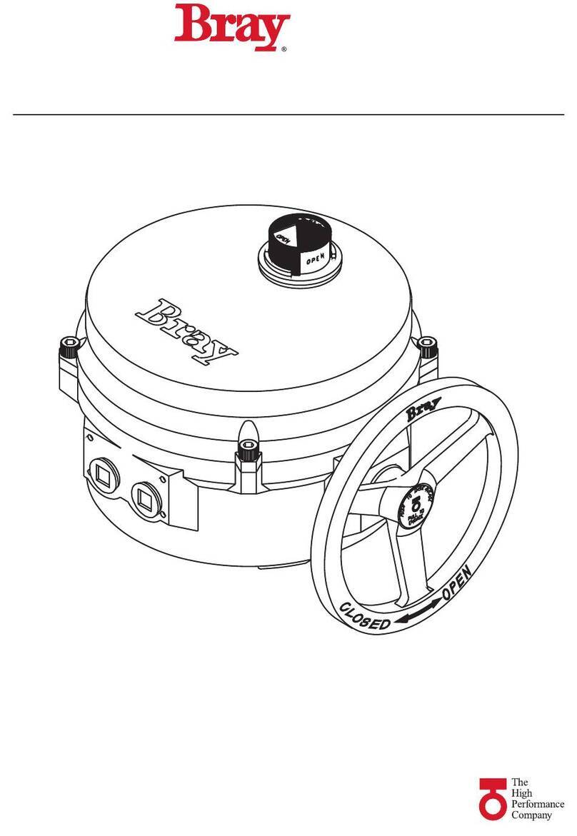
Bray 71 Seires User manual

Series Modulating Controller
ELECTRIC ACTUATOR
Installation Operation and Maintenance Manual
THE HIGH PERFORMANCE COMPANYBRAYCOMMERCIALDIVISION.COM

This Page Intentionally Left Blank

1
Series 71 – Modulating Controller - Electric Actuator
Installation, Operation and Maintenance Manual
FOR MORE INFORMATION ON THIS PRODUCT AND OTHER BRAY PRODUCTS
PLEASE VISIT OUR WEBSITE – wwwbraycommercialdivisioncom
Table of Contents
Definition of Terms . . . . . . . . . . . . . . . . . . . . . . . . . . . . . . . . . . . .
Safety . . . . . . . . . . . . . . . . . . . . . . . . . . . . . . . . . . . . . . . . . . .
Hazard Free Use . . . . . . . . . . . . . . . . . . . . . . . . . . . . . . . . . . .
Qualified Personnel . . . . . . . . . . . . . . . . . . . . . . . . . . . . . . . . .
Quick Start Guide . . . . . . . . . . . . . . . . . . . . . . . . . . . . . . . . . . . . .
Description of Operation. . . . . . . . . . . . . . . . . . . . . . . . . . . . . . . . .
User Interface . . . . . . . . . . . . . . . . . . . . . . . . . . . . . . . . . . . . . . .
Product Settings . . . . . . . . . . . . . . . . . . . . . . . . . . . . . . . . . . .
Configurable Settings . . . . . . . . . . . . . . . . . . . . . . . . . . . .
Description of Settings . . . . . . . . . . . . . . . . . . . . . . . . . . . .
Operating Modes . . . . . . . . . . . . . . . . . . . . . . . . . . . . . . . . . .
Remote Operation . . . . . . . . . . . . . . . . . . . . . . . . . . . . . .
Manual Operation . . . . . . . . . . . . . . . . . . . . . . . . . . . . . . .
Command Signal Calibration . . . . . . . . . . . . . . . . . . . . . . . .
Autocalibration . . . . . . . . . . . . . . . . . . . . . . . . . . . . . . . .
Status Indication. . . . . . . . . . . . . . . . . . . . . . . . . . . . . . . . . . .
Direction Indicators . . . . . . . . . . . . . . . . . . . . . . . . . . . . . .
Fault Status . . . . . . . . . . . . . . . . . . . . . . . . . . . . . . . . . .
Calibration . . . . . . . . . . . . . . . . . . . . . . . . . . . . . . . . . . .
Heartbeat . . . . . . . . . . . . . . . . . . . . . . . . . . . . . . . . . . .
Hardware Description . . . . . . . . . . . . . . . . . . . . . . . . . . . . . . . . . .
Terminal Connections . . . . . . . . . . . . . . . . . . . . . . . . . . . . . . . .
Input Signal - Required Connection. . . . . . . . . . . . . . . . . . . . .
Output Signal . . . . . . . . . . . . . . . . . . . . . . . . . . . . . . . . .
Auxiliary Signals. . . . . . . . . . . . . . . . . . . . . . . . . . . . . . . .
Power - Required Connection . . . . . . . . . . . . . . . . . . . . . . . .
Limit Switch Header - Required Connection . . . . . . . . . . . . . . . .
FB Pot Header - Required Connection . . . . . . . . . . . . . . . . . . .
Heater Header . . . . . . . . . . . . . . . . . . . . . . . . . . . . . . . . .
Motor - Required Connection . . . . . . . . . . . . . . . . . . . . . . . .
Troubleshooting Guide . . . . . . . . . . . . . . . . . . . . . . . . . . . . . . . . . .
Resolving Issues . . . . . . . . . . . . . . . . . . . . . . . . . . . . . . . . . . .
Potentiometer Adjustment . . . . . . . . . . . . . . . . . . . . . . . . . . . . .

2
Series 71 – Modulating Controller - Electric Actuator
Installation, Operation and Maintenance Manual
READ AND FOLLOW THESE INSTRUCTIONS
SAVE THESE INSTRUCTIONS
1.0 DEFINITION OF TERMS
WARNING
Indicates a potentially hazardous situation which if not avoided could result in death
or serious injury
CAUTION
Indicates a potentially hazardous situation which if not avoided may result in minor
or moderate injury
NOTICE
Indicates a potential situation which if not avoided may result in an undesirable result
or state including property damage

3
Series 71 – Modulating Controller - Electric Actuator
Installation, Operation and Maintenance Manual
2.0 SAFETY
Hazard Free Use
This device left the factory in proper condition to be safely installed and
operated in a hazard-free manner. The notes and warnings in this document
must be observed by the user to ensure hazard-free operation of this device.
All necessary precautions need to be taken to prevent damage due to rough
handling, impact, or improper storage. Do not use abrasive compounds to
clean the device, or scrape its surfaces with any objects.
Configuration and setup procedures for this device are described in this
manual. Proper configuration and setup are required for the safe operation of
this device.
The control system in which this device is installed must have proper
safeguards to prevent injury to personnel, or damage to equipment, should a
failure of system components occur.
WARNING
The device generates large mechanical force during normal operation
Qualified Personnel
WARNING
The actuator must only be installed commissioned operated and repaired by qualified
personnel
Installation commissioning operation and maintenance must be performed under
strict observation of all applicable codes standards and safety regulations
As per this document, a qualified person is one who is trained in:
1. The operation and maintenance of electric equipment and systems in
accordance with established safety practices.
2. Procedures to energize, de-energize, ground, tag and lock electrical
circuits and equipment in accordance with established safety practices.
3. The proper use and care of personal protective equipment (PPE) in
accordance with established safety practices.
4. First aid.

4
Series 71 – Modulating Controller - Electric Actuator
Installation, Operation and Maintenance Manual
3.0 QUICK START GUIDE
WARNING
Turn off all power and lockouttag out service panel before installing or modifying any
electrical wiring
Refer to the actuator manual before adjusting or replacing any actuator
components
Terminate the customer connections at the S Servo terminals in
accordance with the actuator wiring diagram
a To reduce the propagation of noise on the customer cables power
lines and signal lines should not be routed together
b Signal lines should be shielded and the shield line should only be
grounded at one end preferably at the controller
Apply power to the S Servo
a Verify that the Heartbeat LED is illuminated and flashing on and off
Set the Input Command signal type
Set the Feedback (Output) signal type
Verify (or adjust) the travel limits in the actuator
a Bray actuators are shipped with the travel switches in the factory
default position – close travel limit set at degrees and the open
travel limit at degrees
b If the travel limit switch settings are moved from the factory default
position the feedback potentiometer may need to be adjusted for
autocalibration to complete
Perform the Input Signal Calibration routine
Perform the Autocalibration routine
a If autocalibration completes then the product is ready for service
b If autocalibration fails then move to step
Using the Input Command signal command the actuator to the fully
opened position
a Observe the S Servo as it operates and correct any faults that
occur Refer to the Troubleshooting guide for more information
Using the Input Command signal command the actuator to the fully
closed position
a Observe the S Servo as it operates and correct any faults that
occur
Return to Step

5
Series 71 – Modulating Controller - Electric Actuator
Installation, Operation and Maintenance Manual
4.0 DESCRIPTION OF OPERATION
The Bray Series Servo provides complete modulating control and
monitoring of the Bray Series Electric Actuator The basic function of the
S Servo is to position the S Actuator in response to a command signal
from a process controller The process controller contains a desired process
set point entered by the user and continually monitors the process variable
(such as flow rate tank level etc) through some type of sensor Varying the
command signal to the S Servo will cause the actuator to change position
which will move the associated control valve to modify the process variable
The process controller continually calculates and transmits the appropriate
command signal to the S Servo to maintain the process at the desired set
point
The command signal to the S Servo can be various DC voltage ranges (-
V -V -V) or a -mA current source The S Servo simultaneously
provides a feedback output signal representing the current actuator
position The retransmission output signal reported by the S Servo can
also be various DC voltage ranges (-V -V) or a -mA current source
These settings along with specific operating modes are enabled by three
simple pushbuttons

6
Series 71 – Modulating Controller - Electric Actuator
Installation, Operation and Maintenance Manual
Product Settings
The product settings determine how the S Servo will respond to
commands from the process controller These must be defined and verified
before operation begins The settings that can be adjusted on the S Servo
are
• “Input” – InputCommand Signal
• “Output” – OutputFeedback Signal
All units’ ship with default settings from the factory
Feature Setting Configurable?
Input Signal -mA Yes
Output Signal -mA Yes
Failure Position Last No
Dead Band Control No
Heater Setpoint C No
Figure S Servo Default Settings
5.0 USER INTERFACE
The S Servo features a rich LED-based menu that displays both
configurable settings and operational status Indicators are grouped
together based on function shown by their respective label(s) Without
any user interaction the S Servo will display the factory default product
settings valve status and fault status
Figure V S Servo

7
Series 71 – Modulating Controller - Electric Actuator
Installation, Operation and Maintenance Manual
Configurable Settings
Settings can be changed locally by utilizing the push-button associated with
each product setting Each push-button is labeled and placed below a set
of LEDs with individual labels corresponding to the setting Settings are
changed using the push-button The next LED in the sequence will illuminate
once the push-button is pressed
4-20mA
0-10V
0-5V
INPUT SIGNAL
4-20mA
0-10V
0-5V
OUTPUT SIGNAL
2-10V
Figure Servo Push Button Menu Flow
Description of Settings
Input Signal Type - Configurable
Input signals position the valve under control based on the magnitude of
the signal The minimum value corresponds to the closed position and the
maximum value to the open position Only one input signal can be active at
a time
Input Setting Description
-mA (default)
Analog Current Range
Minimum mA
Maximum mA
-V
Analog Voltage Range
Minimum V
Maximum V
-V
Analog Voltage Range
Minimum V
Maximum V
-V
Analog Voltage Range
Minimum V
Maximum V
Figure Servo Input Settings

8
Series 71 – Modulating Controller - Electric Actuator
Installation, Operation and Maintenance Manual
Output Signal Type - Configurable
Output signals report the position of the valve under control based on the
magnitude of the signal The minimum value corresponds to the closed
position and the maximum value to the open position Only one output
signal can be active at a time
Output Setting Description
-mA (default) Analog Current Range
Minimum mA
Maximum mA
-V Analog Voltage Range
Minimum V
Maximum V
-V Analog Voltage Range
Minimum V
Maximum V
Figure S Servo Input Settings
Failure Position Last
The Failure Position determines how the S Servo positions the valve
upon loss of input signal Loss of input signal occurs when the input signal
received is outside the valid range of the selected Input Signal Type eg
an input signal of less than mA for the -mA input The S Servo will
position the valve at the last valid commanded position before loss of signal
Dead Band Control
Dead Band Control determines the acceptable offset between the position
command provided by the input command and the current position
of the actuator determined from the feedback signal provided by the
potentiometer This value is a percentage of the full input range and creates
an inactive area centered around the desired set point For example for
a -V input command the Dead Band setting allows the actuator
position to be offset from the desired set point by up to V in either
direction creating a dead band with a span of V
Heater Setpoint
The S Servo maintains surveillance of the internal temperature of the
actuator If the internal temperature rises above F (C) the S Servo
will automatically turn off the W anti-condensation heater
Operating Modes
Remote Operation
By default the operating mode of the S Servo is remote mode where
the valve is positioned based on input signals Exiting another mode of
operation generally results in the S Servo returning to remote mode

9
Series 71 – Modulating Controller - Electric Actuator
Installation, Operation and Maintenance Manual
Manual Operation
Manual operation of the actuator is performed via declutchable handwheel
The S Servo will continue to operate as if in remote mode though it
will not be able to actuate to a new setpoint until the manual mode is
disengaged See the S IOM for additional details
Command Signal Calibration
A command signal calibration routine is provided to increase accuracy by
accounting for small static defaults associated with the input circuitry It is
suggested to perform this once at commissioning prior to performing the
autocalibration routine
First select the desired input signal mode using the input pushbutton until
the appropriate LED is highlighted If -mA mode is selected disconnect
wiring from the command signal terminals If a voltage mode is selected
disconnect wiring from the command signal terminals and attached a wire
jumper between the command () and command (-) terminals
Press and release the calibration (Cal) button once the calibration LED
begins to flash rapidly Within second press and release the Input mode
button Most LEDs will turn off The Heartbeat LED will continue to operate
and the Fault LED may continue to flash
Once the LEDs turn back on the calibration is complete and the calibration
will be stored in the non-volatile memory Reconnect the command signal
wiring to the command signal terminals
WARNING
The input signal calibration routine must be run if the input signal type is changed
from a voltage mode to a current mode or vice versa
Autocalibration
Autocalibration mode is entered by pressing and holding the Autocalibration
(Cal) button for at least second Entering Autocalibration mode starts the
autocalibration sequence a series of commands performed by S Servo on
the actuator to determine the operating points During the autocalibration
sequence the S Servo should be monitored to ensure it operates
correctly The calibration LED will flash slowly to show that autocalibration
has been entered and will continue to flash at the end of travel until
autocalibration completes Upon completion of the autocalibration
sequence calibration LED will turn off
If the fault indication lights illuminate during autocalibration then the
autocalibration sequence could not be successfully completed Refer to the
troubleshooting section for more information
No other operating modes can be entered during autocalibration and
entering autocalibration mode will override any previous mode of operation

10
Series 71 – Modulating Controller - Electric Actuator
Installation, Operation and Maintenance Manual
Status Indication
These are all indicators that report key information on the operation and
functional status of the S Servo and actuator
Figure - S Servo Setting Buttons and Status Indication LEDs
Direction Indicators
The Open (green) and Close (red) indicators located at the top left of the
display show the current direction of travel When the actuator is energized
the corresponding indicator will flash to indicate travel The green indicator
will be lit if the open travel limit is reached The red indicator will remain lit if
the close travel limit is reached
OPEN (Green LED) CLOSE (Red LED) DESCRIPTION OF ACTIVITY
OFF OFF No power or actuator is stopped
mid-travel
ON (solid) OFF Stopped at fully open position
ON (solid) ON (flashing) At fully open position moving in
the closed direction
OFF ON (flashing) Moving in the closed direction
OFF ON (solid) Stopped at full closed position
ON (flashing) ON (solid) At full closed position moving in
the open direction
ON (flashing) OFF Moving in the open direction
ON (flashing) ON (flashing) Fault condition where both limit
switches are activated Fault LED
is also ON (flashing)
ON ON Motor Braking – Both LEDs may
momentarily activate during
motor braking The Fault LED will
not turn on during this operation
Figure – Direction Indication LED Status Description

11
Series 71 – Modulating Controller - Electric Actuator
Installation, Operation and Maintenance Manual
Fault Status
The Fault LED located at the bottom left will turn on during a fault
condition The occurrence of a fault indicates that user intervention is
required to restore operation and these indicators attempt to provide the
diagnostic information needed to accomplish this
Fault LED (flashing) Other LED Fault Condition
-mA Input LED flashing Command Signal Fault Input signal is
-mA mode and the input signal is less
than mA or greater than mA
-V Input LED flashing Command Signal Fault Input signal
is -V mode and the input signal is
greater than V
-V Input LED flashing Command Signal Fault Input signal is
-V mode and the input signal is greater
than V
-V Input LED flashing Command Signal Fault Input signal is
-V mode and the input signal is less
than V or greater than V
Output LED flashing
(selected output mode)
Feedback Potentiometer Fault
potentiometer voltage is outside of the
V-V range when near limits
Calibration LED Calibration Fault Calibration failed due
to Feedback Potentiometer Fault or the
motor was not able to reach end of travel
in expected time
Open LED & Close LED
both flashing
Limit Switch Fault Both limit switches
activated at the same time
Figure – Fault Indication LED Status Description
Refer to the Troubleshooting section for the actions required to clear a fault
Calibration
The calibration (CAL STATUS) LED indicator located at the bottom right
serves as a calibration status indicator for the S Servo
Calibration (CAL STATUS) LED Description
OFF Autocalibration routine previously
completed successfully
ON (slowly flashing) S Servo operating using default factory
calibration settings
ON (quickly flashing) Calibration routine in progress
Figure – Calibration Status LED Status Description

12
Series 71 – Modulating Controller - Electric Actuator
Installation, Operation and Maintenance Manual
CAUTION
If cams or potentiometer are adjusted the previous calibration settings will not apply
to the new setup Re-run the calibration routine to avoid unexpected behavior
Heartbeat
The heartbeat indicator at the top right serves as status indicators for the
S Servo No matter what operation is performed these indicators should
be flashing on and off If they are not flashing refer to the Troubleshooting
section

13
Series 71 – Modulating Controller - Electric Actuator
Installation, Operation and Maintenance Manual
6.0 HARDWARE DESCRIPTION
Terminal Connections
WARNING
Turn off all power and lockouttag out service panel before installing or modifying any
electrical wiring
There are two categories of connections voltage level and connection type
Field terminals are provided on the unit for the landing of stripped wires
connecting the S Servo to the field wiring needed for it successfully
operate All field terminals are positioned on the left side of the controller
easily accessible facing the conduit entries Internal actuator connections
are made at the factory and should not require any customer adjustment
Auxiliary switches are provided voltage free and rated for operation up to
A at VAC
Field Terminals Internal Connections
High voltage ( V) Power (Live Neutral) Motor Terminals
Heater Header
Low voltage ( V) Input Signal
(Input Input-)
Output Signal
(Output Output-)
FB Pot Header
Limit Switch Header
Voltage Free Auxiliary Switch
(Com Close Open)
Auxiliary Switch Header
Figure Terminal Connection Categories
A Division of BRAY INTERNATIONAL, Inc.
A Division of BRAY INTERNATIONAL, Inc.
·
·
·
·
·
·
·
·
·
·
·
·
·
·
Figure S Servo Field Wiring

14
Series 71 – Modulating Controller - Electric Actuator
Installation, Operation and Maintenance Manual
NOTICE
Refer to the actuator wiring diagram for wire gauge voltage and temperature limits
of the terminal blocks
All actuator connections should match the actuator wiring diagram
Figure V S Servo wiring diagram

15
Series 71 – Modulating Controller - Electric Actuator
Installation, Operation and Maintenance Manual
Xref C:\BII_Vault\Global\Templates\ACAD\LogoBrayControls1.dwg Xref C:\BII_Vault\Global\Templates\ACAD\LogoBrayControls1.dwg
WD-000579
------
BUSA
S71
120/230V S71 SERVO
AND HEATER (OPTIONAL)
1
NOT RELEASED - DO NOT MANUFACTURE
WD-000579
------
BUSA
S71
120/230V S71 SERVO
AND HEATER (OPTIONAL)
1
NOT RELEASED - DO NOT MANUFACTURE
120/230V
S71 SERVO
(SEE NOTES 7-9)
(SEE NOTES 8-11)
INPUT (+)
INPUT (-)
OUTPUT(+)
OUTPUT(-)
SIGNAL
LIVE
NEUTRAL
POWER
120/230V S71
SERVO
(SEE NOTES 7-9)
(SEE NOTES 8-11)
INPUT (+)
INPUT (-)
OUTPUT(+)
OUTPUT(-)
SIGNAL
LIVE
NEUTRAL
POWER
LIMIT
OPEN
LIMIT
CLOSE
LIMIT CLOSE
POT WIPER
POT COM
LIMIT
OPEN
POT V+
LIVE
NEUTRAL
MOTOR
MOTOR CL
NEUTRAL
CAP
CLOSE
MOTOR OP
CAPACITOR
CAP
OPEN
HEATER
NOTES:
1. HEATER IS OPTIONAL.
2. LIVE, NEUTRAL, & GROUND ARE A SINGLE PHASE POWER SUPPLY.
3. ALL SWITCHES SHOWN IN DEACTIVATED STATE.
4. WHEN USING 0-10VDC MODE, THE COMMON OF THE COMMAND SIGNAL
SHOULD NOT BE GROUND/EARTH REFERENCED.
5. COMMAND SIGNAL AND FEEDBACK SIGNAL MUST BE ISOLATED FROM EACH
OTHER AND ANY OTHER CIRCUITS.
6. COMMAND SIGNAL & FEEDBACK SIGNAL WIRES SHOULD BE SHIELDED
PROPERLY & SHIELD SHOULD BE GROUNDED/EARTHED ON ONE END ONLY,
PREFERABLYTHE CONTROLLER END.
7. FEEDBACK LOOP IS POWERED BY THE SERVO, DO NOT SUPPLY
EXTERNAL POWER.
8. POSITION FEEDBACK DEVICE LOAD IS NOTTO EXCEED 400 OHMS IN
THE 4-20mA CONFIGURATION.
HEATER
(OPTIONAL)
CAM
#4
N.O.
COM N.C.
CAM
#3
N.O.
COM N.C.
CAM
#2
N.O.
COM N.C.
CLOSE
CAM
#1
N.O.
COM N.C.
OPEN
AUX
CLOSE
AUX
OPEN
SWITCH PCB
ACTUATOR
FIELD WIRING
GROUND
NEUTRAL
LIVE
-
+
-
+
POSITION
FEEDBACK
DEVICE
OUTGOING FEEDBACK
SIGNAL (SHIELDED)
COMMAND
SIGNAL
DEVICE
INCOMING COMMAND
SIGNAL (SHIELDED)
CALIBRATION SEQUENCE:
1. CONNECT POWER SUPPLY.
2. SET INPUT AND OUTPUT SIGNAL MODES.
3. CALIBRATE THE INPUT SIGNAL.
·DISCONNECT ALL SIGNAL WIRES FROM INPUT(+)/(-).
·FOR 0-10V, 0-5V, AND 2-10V MODES, SHORT INPUT
(+) TO INPUT (-).
·PRESS THE "CALIBRATE" BUTTON FOR 2 SECONDS.
·IMMEDIATELY PRESS THE INPUT SIGNAL BUTTON.
4. RE-ATTACHTHE INPUT SIGNAL WIRES.
5. PRESS THE "CALIBRATE" BUTTON FOR TWO SECONDS.
6. ACTUATOR WILL SELF-CALIBRATE.
TERMINALS - ELECTRONICS
·
14-24 AWG MAX RANGE, 18 AWG RECOMMENDED
·
PUSH BUTTON CLAMP
·
105 °C, 300V MIN RATEDWIRE
·
STRIP WIRE: .39"-.43" [10-11mm]
·
GROUND WIRE GAUGETO BE EQUALTO LARGEST
SUPPLY CONDUCTOR.
FEEDBACK
POTENTIOMETER
POT PCB
GROUND
NEUTRAL
LIVE
-
+
-
+
POSITION
FEEDBACK
DEVICE
COMMAND
SIGNAL
DEVICE
ACTUATOR
WD-000579 REV 1
FIELD
WIRING
CALIBRATION SEQUENCE:
1. CONNECT POWER SUPPLY.
2. SET INPUT AND OUTPUT SIGNAL MODES.
3. CALIBRATE THE INPUT SIGNAL.
·DISCONNECT ALL SIGNAL WIRES FROM INPUT(+)/(-).
·FOR 0-10V, 0-5V, AND 2-10V MODES, SHORT INPUT
(+) TO INPUT (-).
·PRESS THE "CALIBRATE" BUTTON FOR 2 SECONDS.
·IMMEDIATELY PRESS THE INPUT SIGNAL BUTTON.
4. RE-ATTACHTHE INPUT SIGNAL WIRES.
5. PRESS THE "CALIBRATE" BUTTON FOR TWO SECONDS.
6. ACTUATOR WILL AUTOMATICALLY COMPLETE
SELF-CALIBRATION.
FIELD CONNECTIONS:
14-24 AWG, 18 AWG
RECOMMENDED
105 °C, 300V MIN
RATED WIRE.
STRIP WIRE: .39"-
.43" [10-11mm]
GROUND WIRE GAUGE
TO BE EQUALTO
LARGEST SUPPLY
CONDUCTOR.
O C
BLACK
BLACK
BLACK
RED
GREY
BLUE
RED
WHITE
BLACK
NOTES:
1. HEATER IS OPTIONAL.
2. LIVE, NEUTRAL, & GROUND ARE A SINGLE PHASE POWER SUPPLY.
3. ALL SWITCHES SHOWN IN DEACTIVATED STATE.
4. WHEN USING 0-10VDC MODE, THE COMMON OF THE COMMAND SIGNAL
SHOULD NOT BE GROUND/EARTH REFERENCED.
5. COMMAND SIGNAL AND FEEDBACK SIGNAL MUST BE ISOLATED FROM EACH
OTHER AND ANY OTHER CIRCUITS.
6. COMMAND SIGNAL & FEEDBACK SIGNAL WIRES SHOULD BE SHIELDED
PROPERLY & SHIELD SHOULD BE GROUNDED/EARTHED ON ONE END ONLY,
PREFERABLYTHE CONTROLLER END.
7. FEEDBACK LOOP IS POWERED BY THE SERVO, DO NOT SUPPLY
EXTERNAL POWER.
8. POSITION FEEDBACK DEVICE LOAD IS NOTTO EXCEED 400 OHMS IN
THE 4-20mA CONFIGURATION.
N
OC
GREY
BLACK
WHITE
MOTOR
6W
2
3
1
4
TERMINALS - AUX
·
12-22 AWG MAX RANGE, 18
AWG RECOMMENDED
·
SCREW CLAMP WITH WIRE
PROTECTOR
·
105 °C, 300V MIN RATEDWIRE
·
TORQUE SCREW TO 5.5 IN-LBS
·
STRIP WIRE: .177"-.217"
[4.5-5.5mm]
TERMINALS - ELECTRONICS
·14-24 AWG MAX RANGE, 18 AWG RECOMMENDED
·PUSH BUTTON CLAMP
·105 °C, 300V MIN RATEDWIRE
·STRIP WIRE: .39"-.43" [10-11mm]
·GROUND WIRE GAUGETO BE EQUALTO LARGEST
SUPPLY CONDUCTOR.
TERMINALS - AUX
·12-22 AWG MAX RANGE, 18
AWG RECOMMENDED
·SCREW CLAMP WITH WIRE
PROTECTOR
·105 °C, 300V MIN RATEDWIRE
·TORQUE SCREW TO 5.5 IN-LBS
·STRIP WIRE: .177"-.217"
[4.5-5.5mm]
AUX OPEN
AUX CLOSE
AUX COM
Figure V S Servo wiring diagram
Input Signal - Required Connection
Connection for the input signal that positions the valve under control based
on the magnitude of the signal The signal that is present at this connection
should be based on the input setting (see Product Settings)
Input signals are polarized so that miswiring may result in unexpected
behavior Ensure that the wiring diagram is followed when making this
connection
Output Signal
Connection for the output signal that reports the position of the valve under
control based on the magnitude of the signal The signal that is present at
this connection is based on the output setting (see Product Settings)
Output signals are polarized so that miswiring may result in unexpected
behavior Ensure that the wiring diagram is followed when making this
connection

16
Series 71 – Modulating Controller - Electric Actuator
Installation, Operation and Maintenance Manual
Auxiliary Signals
Connection for the auxiliary switches which indicate to the customer when
an end of travel set point has been reached Auxiliary switches are voltage-
free contacts and powered by the customer Signal power is applied via the
auxiliary common terminal and the customer reads a switched voltage signal
from the auxiliary closed or auxiliary open terminal There are no interposing
electronics systems and the associated header provides a direct connection
to these switches Signal protection must be provided by the customer
Power - Required Connection
Power connection that energizes the S Servo and powers the actuator
under control The voltage supplied should be based on the actuator
nameplate voltage and the voltage listed on the S Servo label
The S Servo has an onboard protective fuse that is in line with the input
power connection This protective fuse is rated for A
Limit Switch Header - Required Connection
Connections for the travel limit switches which indicate to the S Servo
when an end of travel set point has been reached The S Servo provides
a logic level voltage at the Open and Close terminals of this connection
Once one of the travel limit switches is engaged the switch at the applicable
connection will engage and pull this pin to V signaling the S Servo to
end travel
For proper operation both travel limit switches should not be engaged
at the same time This would prevent the S Servo from operating the
actuator and results in a fault condition
NOTICE
Low voltage actuator connections are powered by the S Servo An external source
should never be connected to these terminals
FB Pot Header - Required Connection
Connections for the feedback potentiometer used by the controller to
determine the position of the valve
The S Servo provides a logic level voltage across the potentiometer and
then monitors the voltage that is returned on the wiper connection The
wiper voltage will change as the potentiometer is turned due to the rotation
of the cam shaft During autocalibration the S Servo can save the wiper
voltage range and use it to position the actuator accurately and precisely
NOTICE
The S Servo has been programmed to monitor within a specific range of feedback
voltage (V-V) Utilizing a potentiometer other than the factory provided
potentiometer may result in unexpected behavior

17
Series 71 – Modulating Controller - Electric Actuator
Installation, Operation and Maintenance Manual
Heater Header
If the actuator has an internal heater then the heater wires are terminated at
this connection The heater will be powered by the input power connection
Only Bray supplied heaters should be connected to the S Servo
Motor - Required Connection
Connections for the motor that operates the actuator Refer to the actuator
manual for more information on the motor
NOTICE
The output signal is powered by the S Servo An external source should never be
connected to the terminals

18
Series 71 – Modulating Controller - Electric Actuator
Installation, Operation and Maintenance Manual
Refer to the actuator manual before adjusting or replacing any actuator
components Before testing or acting on any issues check for any active
faults
Resolving Issues
Issue Possible Causes Possible Solutions
S Servo does not
turn on when power is
applied Heartbeat is
OFF
Fuse is blown Verify and replace fuse
S Servo is incorrectly
wired
Verify wire connections
against the wiring diagram
S Servo is not receiving
power
Evaluate the Input Power
connection with a multimeter
or oscilloscope
Power is not correct Check the provided power
against the voltage listed for
the S Servo and actuator
Heartbeat is ON and not
flashing Heartbeat is
OFF and not flashing
other LEDs ON
Internal timer fault due to
power surge
Remove and reapply power
Contact Factory
Actuator moves back
and forth near setpoint
(hunting)
Excessive noise on the
signal lines
Use an oscilloscope to
evaluate for the presence of
EMI
Utilize EMI reducing
techniques to mitigate the
issue
S Servo not responding
to command signal
S Servo in
autocalibration mode
Check the indicators for
autocalibration mode
S Servo is incorrectly
wired
Verify wire connections
against the wiring diagram
7.0 TROUBLESHOOTING GUIDE
WARNING
Turn off all power and lockouttag out service panel before installing or modifying any
electrical wiring
This manual suits for next models
1
Table of contents
Other Bray Controllers manuals
Bray
Bray Series 70 User manual

Bray
Bray PA(M)24-27 Series User manual

Bray
Bray Series 70 User manual
Bray
Bray 92 Series User manual

Bray
Bray Series 70 User manual
Bray
Bray 71 Series User manual
Bray
Bray 73 Series User manual
Bray
Bray Series 70 User manual
Bray
Bray Series 70 User manual
Bray
Bray 98 Series User manual
