Brighter Smart 280 User manual

1
User manual
Please read the instructions carefully before use
This
product
manual
contains
important
information
about
the
safe
installation
and
use
of
this
projector.
Please
read
and
follow
these
instructio
ns
carefully
and
keep
this
manual
in
a
safe
place
for
future
reference.
Smart 280 Spot-Beam-Wash

2
2
ONTENTS
1. Precautions and installation ............................................................................................ 3
1.1 the statement ......................................................................................................... 1
1.2 Maintenance .......................................................................................................... 1
1.3 Product Precautions............................................................................................... 1
1.4 Product Introduction............................................................................................... 1
1.5 Connecting signal Cables...................................................................................... 2
1.6 Installation of Lamps.............................................................................................. 2
2. Control panel................................................................................................................... 4
2.1 Key Description...................................................................................................... 4
2.2 the main menu ....................................................................................................... 5
2.2.1 set ................................................................................................................ 5
2.2.2 information................................................................................................... 6
2.2.3 factory .......................................................................................................... 7
3. Channel function ............................................................................................................. 8
3.1 The channel table ................................................................................................. 8
4. Common faults ...............................................................................................................11

3
3
1. Precautions and Installation Precautions and installation
1.1 The statement
Thank you for choosing our products!When this product leaves the factory, the performance is
intact, the package is complete.In order to use this product safely and effectively, please read this
instruction manual carefully and completely before using this product.This manual contains
important installation and use information, please install and operate according to the requirements
of the manual, at the same time, please keep this manual properly for use at any time.Our company
does not assume any responsibility for the damage of the lighting or other performance caused by
the failure of the individual to operate according to the instructions during installation, use and
maintenance.
This manual is subject to technical changes without prior notice.
1.2 maintenance
Disconnect the power supply before performing maintenance.
The lamp should be kept dry, avoid working in damp environment.
Intermittent use will effectively prolong the life of the lamps.
For good ventilation and lighting, take care to clean fans and fan nets and lenses frequently.
Do not use alcohol and other organic solvents to wipe the lamp shell, so as not to cause
damage.
1.3 Product Precautions
This lamp is for professional use only.
Before operation, ensure that the power supply voltage is consistent with
equipment requirements.
Do not place the product in places where it is easy to loose or shake.
In the process of use, if the lamp is abnormal, stop using the lamp in time.
To ensure the service life of the product, do not put the product in the damp or
leaking place, and do not work in the environment where the temperature is above
60 degrees.
When the bulb is used, the voltage change of the power supply should not exceed ±10%. If
the voltage is too high, the life of the bulb will be shortened. If the voltage is too low, the light
color of the bulb will be affected.
After power off, it is necessary to use the lamp to cool down fully after 20 minutes before power
on again.
Rotating parts of lamps and lanterns and sticking accessories must be checked regularly,
loose, shaking timely reinforcement, in case of accidents.
To ensure the normal use of this product, please read this instruction carefully.
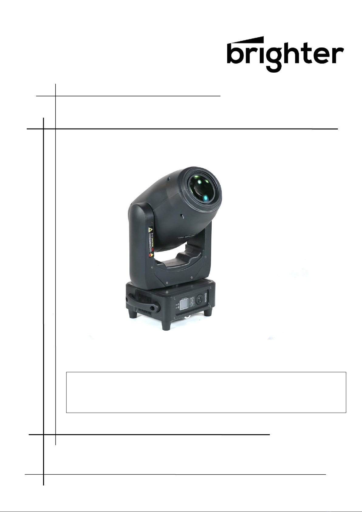
1.4 Product introduction
Input voltage: AC110V-240V / 50-60Hz
Light source:LED White 250w
Life time: 50000 hours
Rated power: 300 W
Channel mode: 17CH
Pan/Tilt movement: 540˚/270˚, adopting a function which resets 16bit accurately and automatically
Dimmer: 0-100%, electronic linear dimming
Frost : 1 independent frost lens, soft and natural light spot
Zoom range: 9-30 degrees
Strobe: 1-25Hz, strobe speed adjustable
Color: 9 colors + white light
Fixed gobo wheel: 9 gobos + white light

4
4
Rotation gobo wheel: 7 glass gobos + white light, each glass gobos can independently rotate
forward and backward
Prism: 3 prisms, independent rotation forward and backward
Working mode: DMX512 control, Auto mode, master/slave mode
RDM Display: LCD
Control signal: international standard DMX512.With the RDM function, you can upgrade software
online and dial address codes
Cooling: Active fan
Material: Aluminum, copper, steel, plastic
Working environment :-20 degrees ~ 40 degrees
Protection level: IP20
Product size: 300*205*542mm
Net weight: 13kg
Color: Static Gobo:
Rotation Gobo
Size:

5
5
1.5 Signal line connection
Lamps feature standard DMX input and output 3-core or 5-core XLR sockets.Please use shielded
twisted-pair signal cable specially for DMX 512;The signal line is generally connected at a
distance of 150 meters. When long-distance signal is transmitted, DMX512 signal amplifier must
be added.
A shielded twisted-pair signal line is used to connect the DMX output port of the controller to the
DMX input port of the first device, and from the DMX output port of the first device to the DMX
input port of the second device, and so on, until all lamps are connected. Then install a terminal
plug on the 3-core jack of the last connecting lamp output in each circuit.(Weld a 4/1W, 120 ω
resistor between the 2 and 3 pins of the 3-core card plug with a needle).
Important: Wires should not touch each other or metal enclosures.
Figure 1 Schematic diagram of DMX signal cable connection
Calculation method of initial address code of lamps:
The start address code of the current lamp is equal to (the start address code of the previous
lamp)+(the number of channels of the lamp)
1: the start address of the first lamp is A001.
2: the basic number of channels of the controller should be greater than or equal to the total
number of channels used by the lamp.
3: Note: when using any controller, each lamp should have its own start address code, if the start
address code of the first lamp is set to A001, the number of lamps is 16CH;The starting address
code of the second lamp is set to A017.The starting address code of the third lamp is set to
A033;And so on,(this setting method also needs to be determined according to different console)
1.6 Installation of lamps and lanterns
Lamps can be placed horizontally, diagonally or upside down.Pay attention to the installation
method when slant and upside down.
As shown Fixed gobo 2, it is necessary to ensure the stability of the installation site before
positioning the lamp. During the installation of the inverted hanging, it is necessary to ensure that
the lamp does not fall off from the support frame, and the safety rope should be used to pass
through the support frame and the handle of the lamp for auxiliary hanging to ensure safety. Prevent
lamp from falling and sliding.FIG. 2 Schematic diagram of upside-down lamps1
During the installation and debugging of the lamps, pedestrians are not allowed to pass under
the lamps. Check regularly whether the safety ropes are worn or the hook screws are loose.
Our company will not assume any responsibility for any consequences caused by falling of the
lamp due to unstable hanging installation.
FIG. 2 Schematic diagram of upside-down lamps1

6
6
2. The control panel
2.1 FUNCTIONS OF BUTTONS
Confirms the displayed value, or activates the displayed function,
or enters the successive menu.
Decreases the value displayed (with auto-repetitions) or passes to
the next item in the menu.
Increases the value displayed (with auto-repetitions) or passes to
the previous item in a menu.
Return to the top level.
Commute from units, tens, hundreds, in the "Address", "Fixture ID"
and "Calibration" menu.
Reversal of the display
To activate this function, press UP and DOWN keys simultaneously while the display is in the rest
mode.This status will be memorised and maintained even for the next time it will be switched on.
To return to the initial state, repeat the operation all over again.
FIG. 3 Schematic diagram of panel keys
USING THE MENU:
1 ) Press “OK” once – “Main Menu” appears on the display.
2) Use the UP and DOWN keys to select the menu to be used:
• Setup (Setup Menu): To set the setting options.
• Option (Option Menu): To set the operating options
• Informations (Informations Menu): To read the counters, software version and other information.
• Manual Control (Manual control Menu): To trigger the test and manual control functions.
• Test (Test Menu): To check the proper functionning of effects
• Advanced (Advanced Menu): Access to the "Advanced menu" is recommended for a trained
technical personnel.
"Advanced" password:988
3) Press “OK” to display the first item in the selected menu.
4) Use the UP and DOWN keys to select the MENU items.

7
7
2.2 Menu Description
FIG. 4 Schematic diagram of main menu
2.2.1 setting
options
instructions
Run Mode
DMX
Slave status: receive DMX signal from controller or master
AUTO
Master status: auto run, send DMX signal to slave
Sound
DMX address
1-512
Press "OK" to enter editing mode.At this time, select hundreds
and press the "up" and "Down" keys to change the address
code.Press OK again to select the ten place edit. Press "OK"
again to select the bits to edit. Press again to exit the edit mode
Device Reset
OFF
ON
Device Reset
Channel mode
17 ch
Standard 17 channel mode
Language
Chinese
Set the language to Chinese
English
Set the language to English
Screen rotation
OFF
Positive display
ON
The screen is displayed inversely
Invert PAN
OFF
Invert PAN off
ON
Invert PAN open
Invert Tilt
OFF
Invert Tilt off
ON
Invert Tilt open
Pan-Tilt Swap
OFF
ON
Exchange pan tilt channel(include fine)
Pan-Tilt encoder
OFF
Use encoder (optocoupler) to determine out of step and
automatically correct position
ON
Correct position without encoder (optocoupler)
DMX signal
keep
Continue running as it is
clear
The motor returns to the position and stops running.
Linear color
OFF
ON
Linear color
Load Default
Press OK to see the confirmation dialog box. Press OK again to
restore the default Settings
2.2.1 manually
Consistent with channel table!
2.2.3 factory
The calibration
Pan
After entering the sub-interface, you can adjust the
reset position of the X axis, Y axis and other motors to
compensate for errors in hardware installation. The
Tilt
Color

8
8
Gobo
adjustment range is -128~+127, +0 means no
adjustment.
Focus
Dimmer
Prism 1 cal
Prism 2 zero
Prism 2 cal
Frost
Clear
2.2.4 information
options
instructions
Hall state
0000000
0 when magnetic is detected, 1 otherwise
Pan wheel step
0000
In the positive direction, the step value should
increase, in the opposite direction, the step value
should decrease.The same value is normal every time
you turn to the same point
Tilt wheel step
0000
In the positive direction, the step value should
increase, in the opposite direction, the step value
should decrease.The same value is normal every time
you turn to the same point
Authority hours
9999
9999 means no encryption and can be used for a long
time.
Other values indicate the remaining use time, with
encryption;
Common error instructions
Common error
messages
instructions
MT board connection
failed. Procedure
Motor board is not responding.The serial communication line
connecting the display board to the motor board is faulty, or the motor
board is faulty.
The Pan reset fails
Pan photoelectric switch, or X-axis motor or motor board problem
The Tilt reset fails
Tilt photoelectric switch, or Y motor or motor board problem
Pan Hall error
Pan axis Hall, or motor plate problem
Tilt Hall error
Tilt Hall, or motor plate problem
The color disk failed
to reset. Procedure
Color plate Hall, or color plate motor problem
Failed to reset the
Gobo disk
Gobo plate Hall, or Gobo plate motor problem
The focus reset failed
There is a problem with the focusing hall or the focusing motor
Bulb control failure
Failed to light or extinguish the bubble. The light lighter or bulb is faulty

9
9
3. Channel function
3.1 The 17 channel
CH
Detail
1
Pan
2
Pan fine
3
Tilt
4
Tilt fine
5
Pan tilt speed
6
Dimmer
7
Shutter/ strobe
8
Color plate
9
Fixed gobo
10
Glass gobo
11
Glass Gobo rotation
12
Focusing
13
Zoom
14
Prism
15
Prism rotating
16
Frost
17
Reset
17 DMX Channel Details
Channel
Function
Value
Detail
1
Pan
000-255.
Pan
2
Pan fine
000-255.
Pan fine
3
Tilt
000-255.
Tilt
4
Tilt fine
000-255.
Tilt fine
5
Pan tilt speed
000-255.
From fast to slow

10
10
6
Dimmer
000-255.
From dark to bright
7
Shutter/
strobe
000-003.
004-250.
251-255.
Brake light off
Strobe from slow to fast
Light switch open → (controlled by dimming
channel)
8
Color plate
000-002
003 -005
006- 008
009 - 011
012- 014
015- 017
018- 020
021- 023
024- 026
027- 029
030- 032
033- 035
036- 038
039- 041
042- 044
045- 047
048- 050
051- 053
054- 056
057- 059
060-159
160 -205
206 - 255
The white light
White light + color 1
Color 1
Color 1 plus color 2
Color 2
Color 2 plus color 3
Color 3
Color 3 plus color 4
Color 4
Color 4 plus color 5
Color 5
Color 5 plus color 6
Color 6
Color 6 plus color 7
Seven colors
Color 7 plus color 8
Color 8
Color 8 plus color 9
Color 9
Color 9 + white light
Color linear
Forward flow (from fast to slow)
Reverse flow (from slow to fast)

11
11
9
Fixed gobo
000 - 009
010 - 019
020 - 029
030 - 039
040 - 049
050 - 059
060 - 069
070 - 079
080 - 089
090 - 099
100 - 104
105 - 109
110 - 114
115 - 119
120 - 124
125 - 129
130 - 134
135 - 139
140 - 144
145-200
201 - 255
White
Fixed gobo 1
Fixed gobo 2
Fixed gobo 3
Fixed gobo 4
Fixed gobo 6
Fixed gobo 7
Fixed gobo 8
Fixed gobo 9
White shake (from slow to fast)
Fixed gobo 1 shake (from slow to fast)
Fixed gobo 2 shake (from slow to fast)
Fixed gobo 3 shake (from slow to fast)
Fixed gobo 4 shake (from slow to fast)
Fixed gobo 5 shake (from slow to fast)
Fixed gobo 6 shake (from slow to fast)
Fixed gobo 7 shake (from slow to fast)
Fixed gobo 8 shake (from slow to fast)
Fixed gobo 9 shake (from slow to fast)
Reverse flow (from fast to slow)
Forward flow (from slow to fast)
10
Glass gobo
000 - 009
010 - 019
020 -029
030 -039
040 - 049
050 - 059
060 - 069
070- 079
080- 089
090- 099
100- 109
110- 119
120 - 129
130- 139
140- 149
150- 200
201- 255
White
Gobo 1
Gobo 2
Gobo 3
Gobo 4
Gobo 5
Gobo 6
Gobo 7
Gobo 1 shake (from slow to fast)
Gobo 2 shake (from slow to fast)
Gobo 3 shake (from slow to fast)
Gobo 4 shake (from slow to fast)
Gobo 5 shake (from slow to fast)
Gobo 6 shake (from slow to fast)
Gobo 7 shake (from slow to fast)
Reverse flow (from fast to slow)
Forward flow (from slow to fast)

12
12
11
Glass Gobo
rotation
000-127.
128-191.
192-255.
Angle adjustment
Reverse from fast to slow
Forward from slow to fast
12
Focusing
000-255.
Gobo clarity from far to near
13
Zoom
000-255.
From big to small
14
Prism
000-127.
128-255.
None
Prism
15
Prism
rotating
000-127.
128-191.
192-255.
Prism Angle adjustment
Reverse rotation (from fast to slow)
Forward rotation (from slow to fast)
16
Frost
000-127.
128-255.
None
Insert frost
17
Reset
000-249.
250-255.
None
Reset
4. Common faults
In view of some common faults, the corresponding solutions are put forward.Any problems that
can't be solved should be dealt with by professionals.Disconnect the power supply before servicing
the lamp.
1. The light bulb not bright
Check whether the voltage matching the lamps and lanterns is installed;
Check whether the lamp power supply connection or control switch is in bad contact;
Check whether electricity supply is insufficient;
Check whether the DMX512 controller is sending instructions.
2. The lamp does not accept the control of the console after normal reset
Check the luminaire digital start address value and function options are correct;
Check whether the connection of communication control line is correct, communication line is
too long or has been interrupted;
Check whether the control equipment fails, check whether the serial access signal amplifier
fails;
Check whether the communication line is too long or other devices interfere with each other;
Optimize wiring, shorten the length of control signal lines, separate high voltage and low
voltage lines;
Add signal amplifier;
High quality shielded twisted-pair cable is used for signal cable;
Connect the signal terminal resistor (120 ohms) at the end of the lamp.
3. Luminaire does not start
Check whether the power supply parameters are consistent with the lamps;
Check the lamps in the long-distance transportation process due to extrusion deformation,
internal parts vibration, moisture and other reasons, resulting in poor contact
Or fall off.
Please check whether the inner conductor connector of the lamp falls off or loosens.
Check the electronic components of the lamp (such as electronic transformer, PCB board,
motor control board, etc.) for loosening, short circuit and burning.

13
13
4. When working, the action of X or Y axis of the lamp is abnormal
Check one by one according to the previous step;
Check whether the transmission belt corresponding to X and Y axis direction in the lamp falls
off and breaks;
Check whether the data feedback receiver (photocoupler) corresponding to X and Y directions
in the lamp is damaged;
Reboot and reset once.
Table of contents
Other Brighter Lighting Equipment manuals

Brighter
Brighter MINI EYE P40 User manual

Brighter
Brighter PRO BAR 18IP User manual

Brighter
Brighter FW200C User manual

Brighter
Brighter FW200CTO User manual

Brighter
Brighter 6X40W User manual

Brighter
Brighter Eye 900 Pro User manual

Brighter
Brighter SMART 150 Beam Plus User manual

Brighter
Brighter X-Dot User manual

Brighter
Brighter Pixel Strobe User manual

Brighter
Brighter Mini Eye User manual