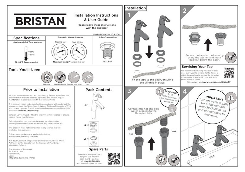
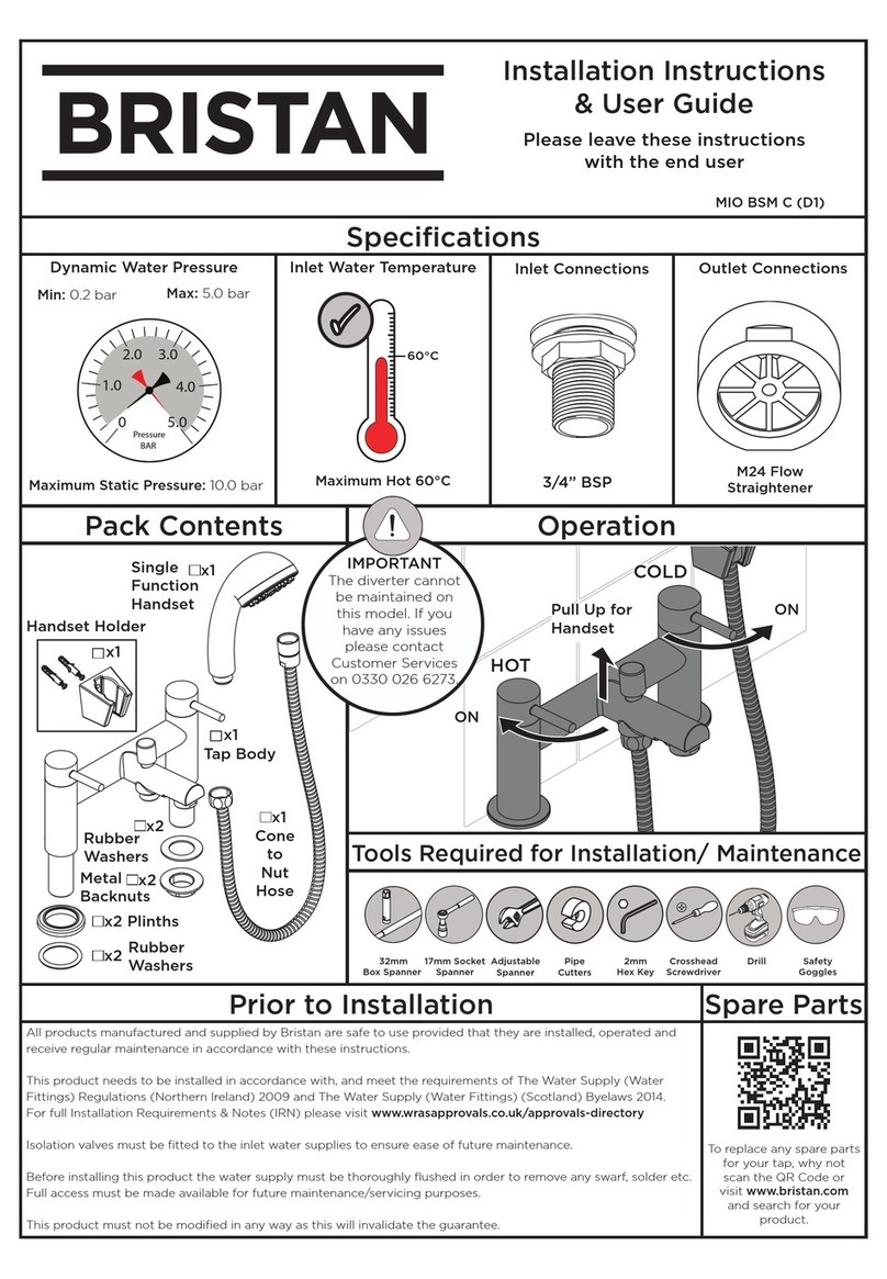
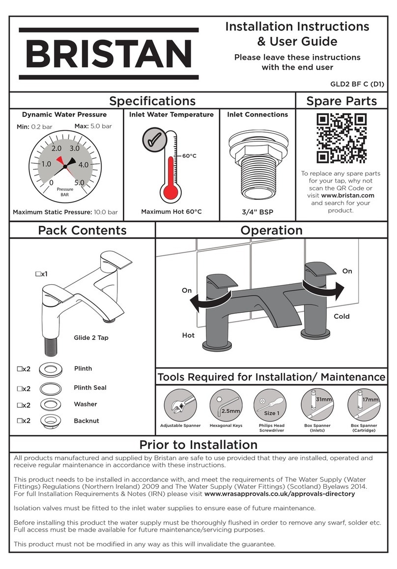
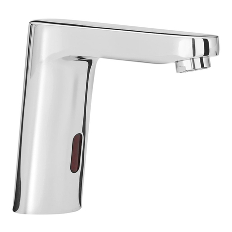
Bristan Blade BL BAS C User manual
Other Bristan Plumbing Product manuals
Bristan
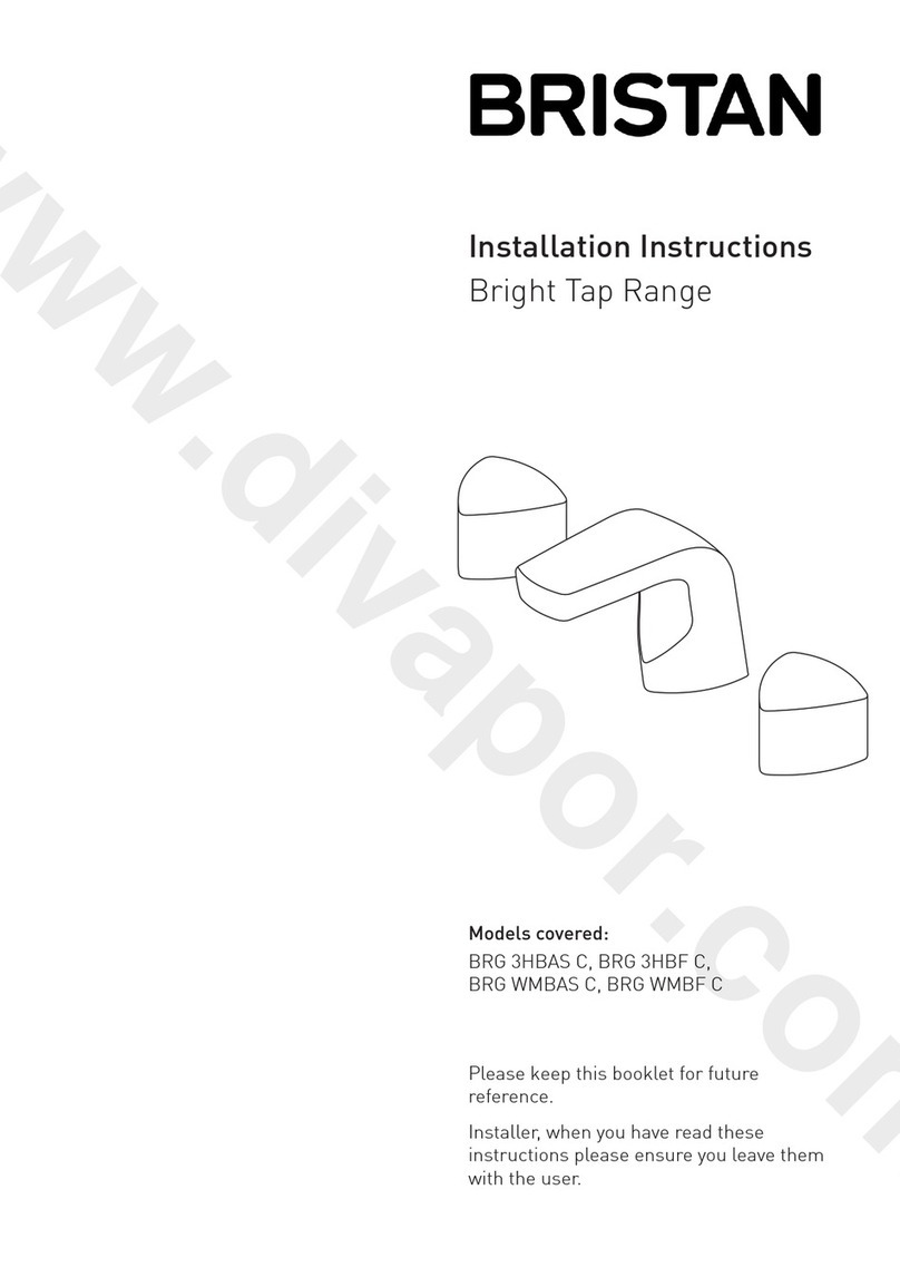
Bristan BRG 3HBAS C User manual
Bristan
Bristan W BTH12 C User manual
Bristan
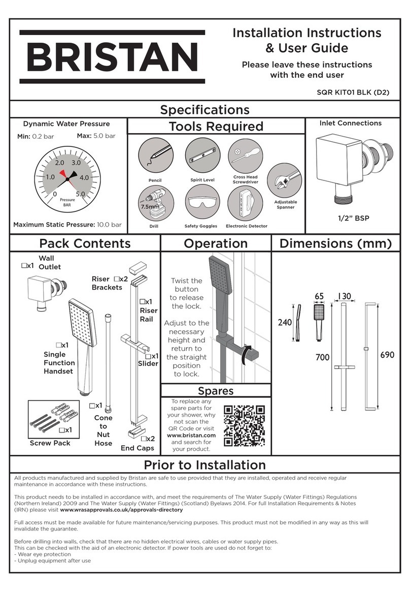
Bristan SQR KIT01 BLK D2 Wiring diagram
Bristan
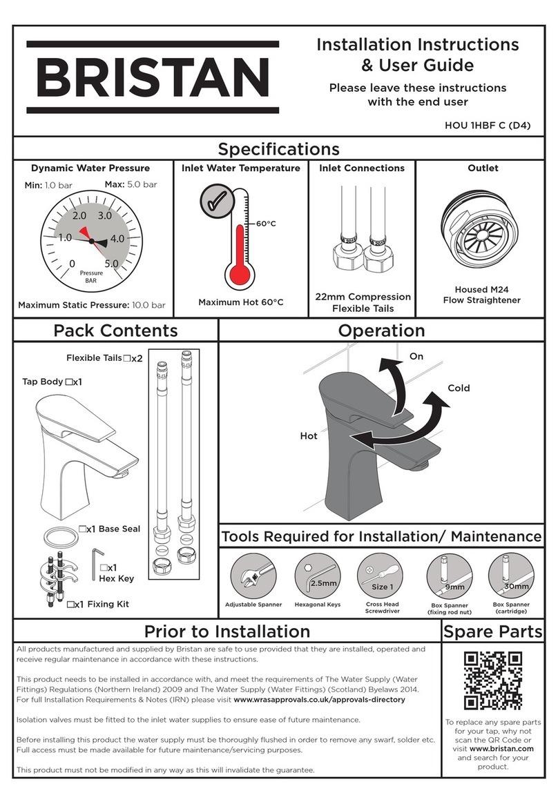
Bristan HOU 1HBF C Wiring diagram
Bristan
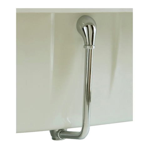
Bristan W BATH07 C Wiring diagram
Bristan
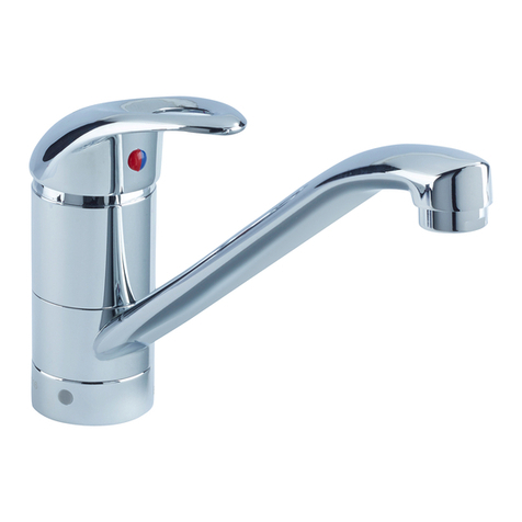
Bristan Java J SFSNK EF C User manual

Bristan
Bristan W BASIN06 C User manual

Bristan
Bristan EXD BAS C User manual
Bristan
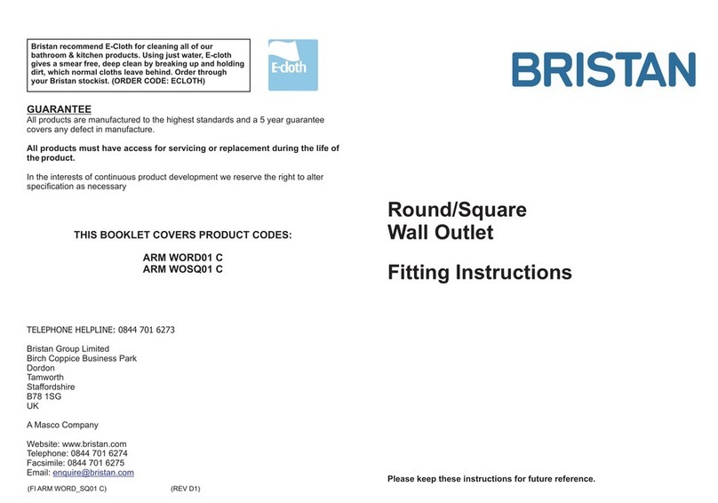
Bristan ARM WORD01 C User manual

Bristan
Bristan JAVA J THBSMVO C Wiring diagram

Bristan
Bristan smile Mounting instructions

Bristan
Bristan Opac Series Mounting instructions

Bristan
Bristan Target TG SNK C User manual
Bristan
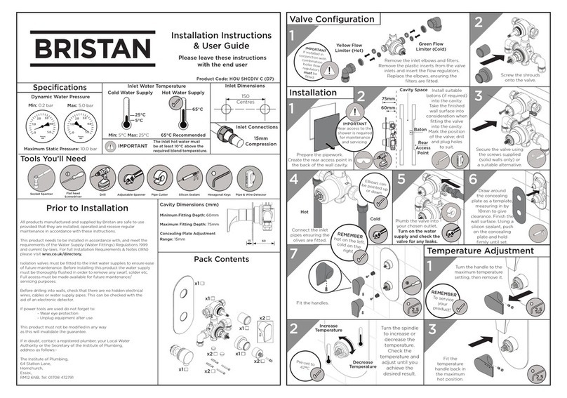
Bristan HOU SHCDIV C (D7) Wiring diagram

Bristan
Bristan JU BAS C User manual

Bristan
Bristan Pisa series Wiring diagram
Bristan
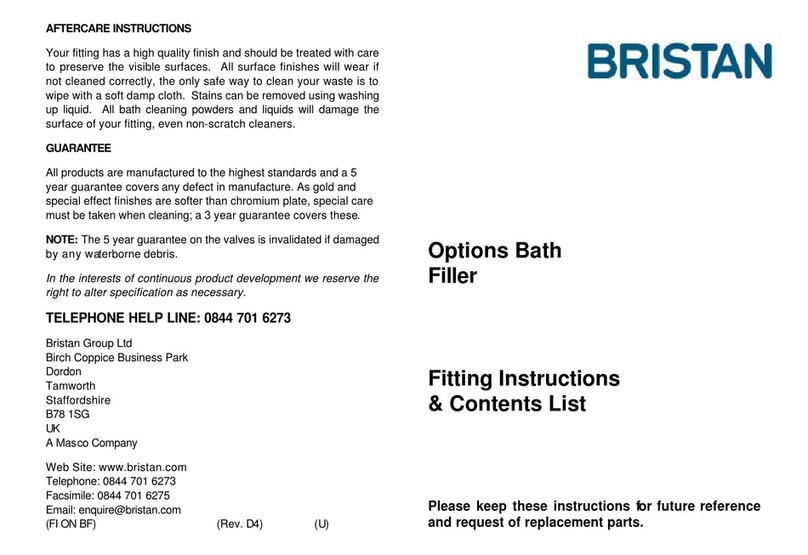
Bristan Options Bath User manual

Bristan
Bristan CART 06734B Original operating manual
Bristan
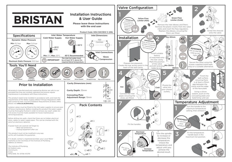
Bristan HOU SHC3DIV C Wiring diagram

Bristan
Bristan Liquorice Kitchen Sink Tap Wiring diagram
Popular Plumbing Product manuals by other brands

Weka
Weka 506.2020.00E ASSEMBLY, USER AND MAINTENANCE INSTRUCTIONS

American Standard
American Standard DetectLink 6072121 manual

Kohler
Kohler K-6228 Installation and care guide

Uponor
Uponor Contec TS Mounting instructions

Pfister
Pfister Selia 49-SL Quick installation guide

Fortis
Fortis VITRINA 6068700 quick start guide

Elkay
Elkay EDF15AC Installation, care & use manual

Hans Grohe
Hans Grohe AXOR Citterio E 36702000 Instructions for use/assembly instructions

baliv
baliv WT-140 manual

Kohler
Kohler Mira Eco Installation & user guide

BELLOSTA
BELLOSTA romina 0308/CC Installation instruction
Crosswater
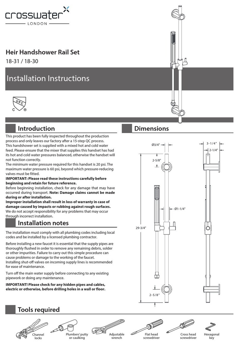
Crosswater Heir 18-31 installation instructions
