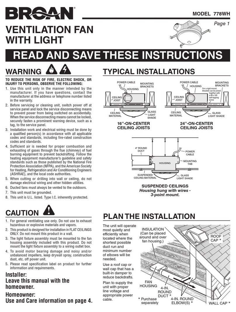
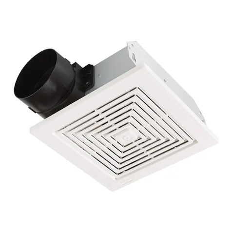
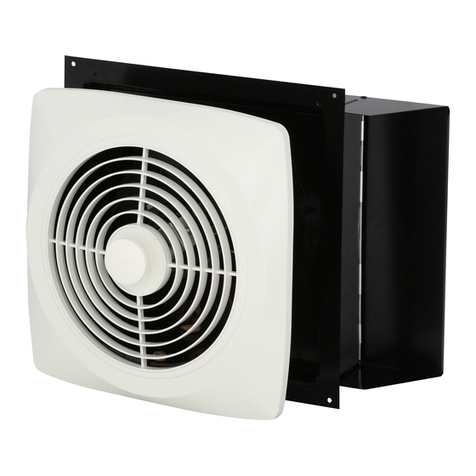
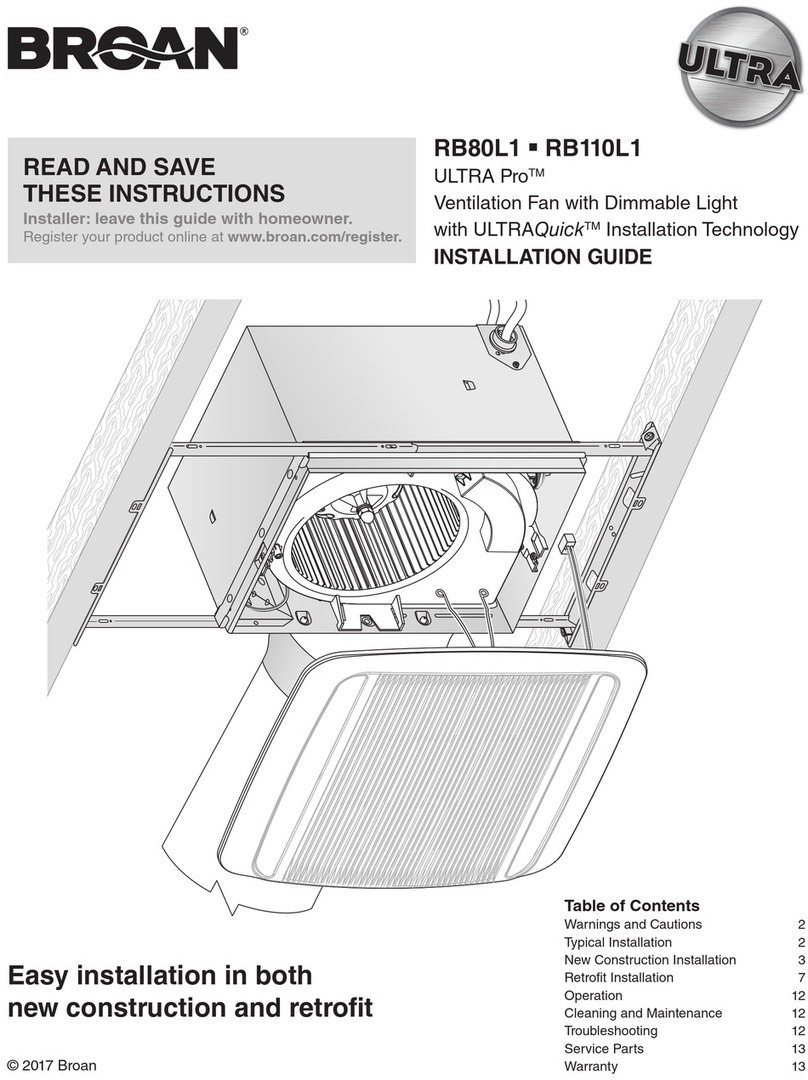
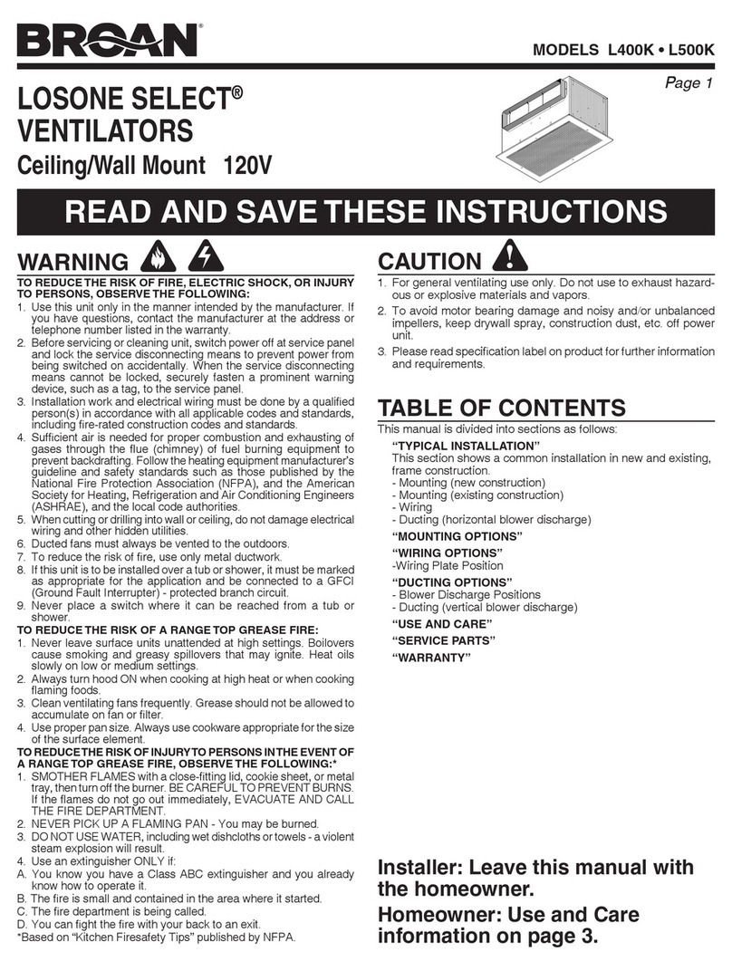
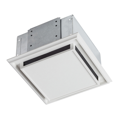
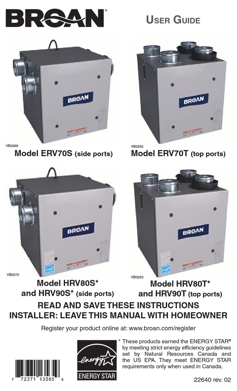
Broan 744C User manual

®
Page 1
MODEL 744C
WARNING
TO REDUCE THE RISK OF FIRE, ELECTRIC SHOCK, OR IN-
JURY TO PERSONS, OBSERVE THE FOLLOWING:
1. Use this unit only in the manner intended by the manufac-
turer. If you have questions, contact the manufacturer at the
address or telephone number listed in the warranty.
2. Before servicing or cleaning unit, switch power off at service
panel and lock the service disconnecting means to prevent
power from being switched on accidentally. When the ser-
vice disconnecting means cannot be locked, securely fasten
a prominent warning device, such as a tag, to the service
panel.
3. Installation work and electrical wiring must be done by a
qualified person(s) in accordance with all applicable codes
and standards, including fire-rated construction codes and
standards.
4. Sufficient air is needed for proper combustion and exhaust-
ing of gases through the flue (chimney) of fuel burning equip-
ment to prevent backdrafting. Follow the heating equipment
manufacturer’s guideline and safety standards, and the local
code authorities.
5. When cutting or drilling into wall or ceiling, do not damage
electrical wiring and other hidden utilities.
6. Ducted fans must always be vented to the outdoors.
7. If this unit is to be installed over a tub or shower, it must be
marked as appropriate for the application and be connected
to a GFCI (Ground Fault Interrupter) - protected branch cir-
cuit.
8. Never place a switch where it can be reached from a tub or
shower.
9. Install this unit in a flat ceiling only.
10. For use in non fire rated installations only.
11. Not for use in environmental air handling spaces.
12. CAUTION - RISK OF FIRE: 75W MAX. LAMP. Use R30,
BR30, PAR30L, or PAR30LN lamps only (75W Max.). For
wet locations (tub or shower) - use PAR30L or PAR30LN
(75W Max.) lamp only. Use no other lamp types. Do not
install a lamp indentified for use only in enclosed luminaries.
13. This unit must be grounded.
CAUTION
!
1. For general ventilating use only. Do not use to exhaust haz-
ardous or explosive materials and vapors.
2. To avoid motor bearing damage and noisy and/or unbal-
anced blower wheels, use the cardboard protector (provided)
to keep drywall spray, construction dust, etc. off power unit.
3. Please read specification label on product for further infor-
mation and requirements.
RECESSED
FAN / LIGHT
READAND SAVE
THESE INSTRUCTIONS
To clean trim ring / baffle: Vacuumwithasoftbrushattachment
or remove trim ring / baffle and clean with a soft cloth and mild
soap or detergent. Dry thoroughly before reinstalling.
To clean insideofhousing:Removetrimring/ baffleandvacuum
inside of housing with a soft brush attachment.
OPERATION
The fan and light can be operated using various combinations
of on/off switches and timer controls:
• Fan and light controlled with single on/off switch
• Fan and light controlled with separate on/off switches
• Fan controlled with on/off switch - light with dimmer switch
• Fan controlled with timer control
Do not use a speed control to operate the fan in this unit.
See “Connect Wiring” section for various wiring options.
CLEANING
MAINTENANCE
Motor is permanently lubricated. Do not oil or disassemble motor.
See “Service Parts” section for a list and illustrations of service parts.
WARRANTY
BROAN-NUTONE CANADA INC. ONE YEAR LIMITED WARRANTY
Broan-NuToneCanadawarrants to the originalconsumerpurchaserof its products that
suchproductswillbefree from defects in materials and workmanshipforaperiodofone
(1) year from the date of original purchase. THEREARE NO OTHER WARRANTIES,
EXPRESSED OR IMPLIED, INCLUDING, BUT NOT LIMITED TO, IMPLIED
WARRANTIES OF MERCHANTABILITY OR FITNESS FOR A PARTICULAR
PURPOSE.
Duringthis one-year period, Broan-NuTone Canada will,at its option, repairor replace,
withoutcharge,anyproduct or part which is foundtobedefectiveunder normal use and
service. THIS WARRANTY DOES NOT EXTEND TO FLUORESCENT LAMP
STARTERS OR TUBES, BULBS OR BATTERIES, FILTERS, DUCT, ROOF CAPS,
WALL CAPSAND OTHER ACCESSORIES FOR DUCTING. This warranty does not
cover(a)normalmaintenance and service or (b) anyproductsorpartswhich have been
subjecttomisuse, negligence, accident, impropermaintenanceor repair (other thanby
Broan-NuToneCanadaoranauthorizedrepresentative),faultyinstallation or installation
contrary to recommended installation instructions.
Thedurationofanyimpliedwarrantyislimited to the one-year period as specified forthe
expresswarranty.
BROAN-NUTONE CANADA’S OBLIGATION TO REPAIR OR REPLACE, AT
BROAN-NUTONE CANADA’S OPTION, SHALL BE THE PURCHASER’S SOLE
AND EXCLUSIVE REMEDY UNDER THIS WARRANTY. BROAN-NUTONE
CANADA SHALL NOT BE LIABLE FOR INCIDENTAL, CONSEQUENTIAL OR
SPECIAL DAMAGES ARISING OUT OF OR IN CONNECTION WITH PRODUCT
USE OR PERFORMANCE. This warranty supersedes all prior warranties.
Toqualifyforwarrantyservice,youmust(a)notifyBroan-NuToneCanadaattheaddress
or telephone number stated below (b) give the model number and part identification
and(c)describe the nature ofanydefect in the productorpart.Atthe time of requesting
warranty service, you must present evidence of the original purchase date.
Date ofInstallation: Builder or Installer:
Model Number and Product Description:
IF YOU NEED ASSISTANCE OR SERVICE:
For the location of your nearest Broan-NuTone Canada Inc. dealer: Dial Toll Free: 1-
888-882-7626
Please be prepared to provide: Product model number • Date and proof of purchase •
Thenature of the difficulty
Broan-NuTone Canada Inc. 1140 Tristar Drive, Mississauga, Ontario L5T 1H9

®
Page 2
MODEL 744C
Two of the most common ways to
connect ductwork to the unit.
ROOF CAP **
4-IN. ROUND
ELBOW**
4-IN. ROUND
DUCT **
WALL
CAP**
Installer: Leave this manual with
the homeowner.
HOUSING
MOUNTING
BRACKET
CEILING
JOIST
POWER
CABLE
TRIMRING / BAFFLE
FINISHEDCEILING
4" ROUND
DAMPER/DUCT
CONNECTOR
PLAN THE INSTALLATION
The unit can be installed anywhere between ceiling joists using
mounting brackets provided.
*Install in a flat ceiling only.
Typical Installation
The unit will operate most quietly and efficiently when located
where the shortest possible duct run and minimum number of
elbows will be needed.
Plan to supply the unit with proper line voltage and appropriate
power cable.
** Purchase separately
INSTALLATION
2. Mark mounting location.
Position unit between joists and extend mounting brackets.
IMPORTANT: Position brackets so there will be an 1/8” gap
between bottom of housing and ceiling material. Markthetop
of keyhole slot on all four mounting brackets.
COOKINGAREA
Do not install above
or inside this area
Cooking
Equipment Floor
45 45
The unit must not be installed above or inside the cooking area
shown.
Do not install in a cooking area.
*
1/8" GAP
1. Install mounting brackets.
Slidetheadjustable mounting brackets into the bracket channels
on the housing.
Bend the tabs on the cardboard protector and insert protector
into opening in housing.
NOTE: The cardboard protector shields the inside of the housing
from drywall spray and construction dust. Do not remove it until
after construction is completed.
CARDBOARD PROTECTOR

®
Page 3
MODEL 744C
HORIZONTALPOWER
CABLE CONNECTION
VERTICAL
POWER
CABLE
CONNECTION
WIRINGPLATE
WHITE
TO
WHITE
BLUE (FAN)
TO
BLACK TOP / BACK
OF HOUSING
3-WIRE PLUS
GROUND
POWER
CABLE
GROUND TO
WIRINGPLATE
Fan operated with separate on/off switch or timer.
Light operated with separate on/off switch
or dimmer switch.
FLUSH
3. Pound in nails.
Remove unit temporarily, and pound nails partially into joists at
all four marked locations.
4. Hang and secure housing.
Hang unit from nails. Check to make sure that there will be a 1/
8” gap between bottom of housing and ceiling material. Pound
nails tight. For wide joist centers: A #8 x 3/8 self-tapping screw
can be used to join extended brackets together and create a
rigid mount. To ensure a noise-free mount, crimp the bracket
channels tightly around mounting brackets.
5. Attach damper/duct connector.
Snap the damper/duct connector onto housing. Make sure that
tabs on the connector lock in housing slots. (Top of damper/duct
connector will be flush with top of housing.)
6. Choose power cable direction.
Remove wiring plate. When re-attached, the wiring plate allows
the power cable to enter unit horizontally or vertically.
7. Connect wiring.
Unit can be wired from outside of housing as shown. Use UL
approved connectors to wire per local codes.
Fan and Light operated with single on/off switch
RED (LAMP) TO RED
WIRINGPLATE
WHITE
TO
WHITE
BLUE AND RED
TO BLACK TOP / BACK
OF HOUSING
2-WIRE PLUS
GROUND
POWER
CABLE
GROUND TO
WIRINGPLATE

®
Page 4
MODEL 744C
SERVICE PARTS
KEY NO. PART NO. DESCRIPTION
1 97014185 Damper / Duct Connector
2 97016382 Housing Assembly
3 98003036 Mounting Bracket (4 req.)
4 98005512 Wiring Adaptor Plate
5 99524804 Blower Wheel *
6 99524805 Motor Bracket / Venturi *
7 99080557 Motor *
97016454 Motor / Motor Bracket Assembly
(includes Key Nos. 6 & 7) *
8 99271323 Receptacle
9 99271322 Thermal Protector
10 99420551 Plastic Wire Clip
11 99770033 Lamp Socket
12 97016664 Lamp Bracket
97016665 Lamp Bracket Assembly
(includes Key Nos. 8 thru 12)
13 99524802 Trim Ring / Baffle with Springs
14 99525160 Baffle Springs (2 req.)
3
2
8
1
5
9
10 12
11
4
99043574A
Order replacement parts by PART NO. - not by KEY NO.
* Lamp Bracket Assembly must be removed to service these
parts.
9. Attach trim ring / baffle to housing.
Remove the cardboard protector from inside the housing collar.
Insert one end of each spring into the holes on the lamp bracket.
Center trim ring / baffle in ceiling opening.
10. Install bulb.
CAUTION - RISK OF FIRE:
75W MAX. LAMP
Use R30, BR30, PAR30L, or PAR30LN lamps only (75W Max.).
For wet locations (tub or shower) - use PAR30L or PAR30LN
(75W Max.) lamp only. Use no other lamp types.
Donot installalampindentifiedfor useonlyin enclosedluminaries.
6
7
13
FINISHED
CEILING
MATERIAL
HOUSING
COLLAR
CLEARANCE
HOLE
SPRINGS
TRIM RING /
BAFFLE
LAMP
BRACKET
Lamp Bracket Assembly
must be removed to
service these parts.
14
8. Finish ceiling.
Cut an opening in finished ceiling material for housing collar.

®
Page 5
MODEL 744C
AVERTISSEMENT
AFIN DE RÉDUIRE LES RISQUES D’INCENDIE, DE CHOC
ÉLECTRIQUE OU DE BLESSURES CORPORELLES, VEUILLEZ
OBSERVEZ LES DIRECTIVES SUIVANTES :
1. N’utilisez cetappareil quede lamanière prévuepar lefabricant. Si
vousavezdesquestions,communiquezaveclefabricantàl’adresse
ouaunuméro detéléphone indiquésdansla garantie.
2. Avant de procéder à la réparation ou à l’entretien de l’appareil,
coupez l’alimentation du panneau électrique et verrouillez
l’interrupteur principal afin d’empêcher que le courant ne soit
accidentellementrétabli.S’ilestimpossibledeverrouillerl’interrupteur
principal,fixezsolidementunmessaged’avertissement,parexemple
uneétiquette,sur lepanneau électrique.
3. Laposedel’appareiletlestravauxd’électricitédoiventêtreeffectués
pardespersonnesqualifiées conformémentàlaréglementation en
vigueur, notamment les codes et normes du bâtiment relatifs à la
protectioncontre lesincendies.
4. Pour éviter lesrefoulements, l’apport d’air doitêtre suffisant pour
brûlerlesgazproduitsparles appareils àcombustionetlesévacuer
dansle conduitde fumée(cheminée). Respectezles directivesdu
fabricantdel’appareildechauffageetcellesdescodesdesautorités
locales.
5. Veillez à ne pas endommager le câblage électrique ou d’autres
équipementsnon apparents lorsde la découpeou du perçagedu
muroudu plafond.
6. Lesventilateurs possédentunconduitdoiventtoujoursêtreventilés
àl’airlibre.
7. Sicet appareildoitêtre installéau-dessusd’une baignoireoud’une
douche, il doit comporter les mentions appropriées pour ces
utilisationset êtreconnecté à uncircuit protégépar un disjoncteur
différentiel(GFCI).
8. Neplacez pas un interrupteuràunendroitaccessibledelabaignoire
oude ladouche.
9. N’installez cetappareil quedansun plafondplat.
10.L’utilisez uniquement dans desinstallationsnonclasséesrésistantes
aufeu.
11. Nel’utilisezpas dansunendroit équipéd’un système detraitement
del’airambiant.
12. ATTENTION - RISQUE D’INCENDIE :AMPOULE DE 75 W MAX.
N’utilisez que des ampoules R30, BR30, PAR30Lou PAR30LN (75 W
max.).Pourlesemplacementsmouillés (bain oudouche)-n’utilisez
que des ampoules PAR30Lou PAR30LN (75 W max.). N’utilisez
aucunautretyped’ampoule.N’installezpasd’ampoulesidentifiées
commeétant destinéesà desluminaires fermés.
13.Cette unitédoit comporterune mise àla terre.
ATTENTION
!
1. Cetappareil nedoit servirqu’à laventilation générale.Il nedoit pas
êtreutilisépour éliminerdesmatières oudesvapeurs dangereuses
ouexplosives.
2. Pourne pasendommager lesroulements du moteur,déséquilibrer
lesrouesduventilateuroulesrendrebruyantes,utilisezleprotecteur
en carton afin de protéger l’appareil de la poussière de plâtre, de
construction,etc.
3. Veuillez lirel’étiquette despécificationsdu produitpour obtenirplus
derenseignements, notammentsur les exigences.
VENTILATEUR /
LUMIAIRE
ENCASTRÉ
VEUILLEZ LIRE CES DIRECTIVES
ET LES CONSERVER
Pour nettoyer la garniture circulaire / déflecteur : Utilisez un
aspirateur avec une brosse souple ou enlevez la garniture circulaire /
déflecteur et nettoyez-le avec un chiffon doux et du savon ou un
détergentdoux. Séchez-lecorrectement avantde leréinstaller.
Pour nettoyer l’intérieur du boîtier : Enlevezlagarniture
circulaire / déflecteur et nettoyez l’intérieur avec un aspirateur muni
d’unebrosse souple.
FONCTIONNEMENT
Le ventilateur et l’éclairage peuvent être commandés par diverses
combinaisons d’interrupteurs et de minuterie :
• Leventilateur etl’éclairagecommandés parun seulinterrupteur
• Leventilateuretl’éclairagecommandéspardesinterrupteursdistincts
• Le ventilateur commandé par un interrupteur - l’éclairage par un
gradateur
• Leventilateurcommandé paruneminuterie
N’utilisezpas une commandede vitessepour fairefonctionner le
ventilateur de cet appareil. Voir la section « Câblage » pour les
différentesoptionsde connexion.
NETTOYAGE
ENTRETIEN
Lemoteur estlubrifié àvie. Ilne doitpas êtrehuilé nidémonté.
Consultezla section “Pièces de rechange”pour la listeet les
illustrationsdes pièces.
MODÈLE
GARANTIE
BROAN-NUTONECANADAINC.GARANTIELIMITÉEDEUNAN
Broan-NuTone Canada garantit à l’acheteur consommateur original, de ses produits qu’ils
sont exempts de défauts reliés aux matériaux ou à la main-d’oeuvre pour une période de
un (1) an à compter de la date d’achat original. IL N’Y A PAS D’AUTRES GARANTIES,
EXPRIMÉESOUIMPLICITES,YCOMPRIS,MAISSANSSELIMITERAUXGARANTIES
IMPLICITESPOURFINDECOMMERCIALISATIONETDECONVENANCEDANSUNBUT
PARTICULIER.
Pendant cette période de un an, Broan-NuTone Canada, à son choix, réparera ou
remplacera,gratuitement,toutproduit ou piècequis’avèredéfectueuxdansdesconditions
normales d’utilisation et d’entretien.
CETTEGARANTIENECOUVREPASLESDÉMARREURSDELAMPESFLUORESCENTES
OULESTUBES,LESAMPOULESOULESBATTERIES, LESFILTRES,LECONDUIT,LES
ÉVENTSDETOITURE,LESÉVENTSMURAUXETLESAUTREACCESSOIRESDECONDUIT.
Cettegarantie ne couvre pas(a) l’entretien et leservice normal ou (b)tout produit ou pièce
endommagés par suite de mauvais usage, négligence, accident, entretien inapproprié ou
réparation (autre que celle effectuée par Broan-NuTone Canada ou un représentant
autorisé),mauvaiseinstallationouinstallationcontraire aumoded’installationrecommandé.
La durée de toute garantie implicite est limitée à une période de un an telle qu’elle est
spécifié pour la garantie exprimée.
L’ENGAGEMENTDEBROAN-NUTONECANADADERÉPAREROUDEREMPLACER,AUCHOIX
DEBROAN-NUTONECANADA,DOITÊTRELASEULEOBLIGATIONEXCLUSIVEENVERTU
DECETTEGARANTIE.BROAN-NUTONECANADANEDOITPASÊTRETENUERESPONSABLE
DES DOMMAGES DIRECTS, INDIRECTS OU SPÉCIAUX SURVENANT À CAUSE DE
L’UTILISATIONOUDELAPERFORMANCEDESESPRODUITSOUENRAPPORTAVEC
CELLES-CI.
Cette garantie annule toutes les garanties précédentes.
Pour obtenir le service après-vente aux fins de la garantie, vous devez (a) aviser Broan-
NuTone Canada à l’adresse ou au numéro de téléphone ci-dessous, (b) donner le numéro
du modèle et l’identification de la pièce et (c) décrire la nature de tout défaut du produit ou
delapièce.Lorsque vous demanderez le service après-vente aux finsdelagarantie,vous
devez présenter une preuve de la date d’achat originale.
Date d’installation Enterpreneur ou installateur
N0 de modèle et description du produit
POUROBTENIRDEL’ASSISTANCEOUDUSERVICE:
Pour connaître le Centre de service Broan-NuTone Canada Inc. autorisé indépendant le
plus proche:
Composez le numéro sans frais: 1-888-882-7626
Garder à portée de la main : le numéro du modèle • la date et la preuve d’achat • le type de
problème
Broan-NuTone Canada Inc. 1140 Tristar Drive, Mississauga, Ontario L5T 1H9
®
Page 6
MODEL 744C
Deux des façons les plus courantes de raccorder
les conduits à l’appareil.
ÉVENT DE TOITURE **
COUDE ROND DE 10 CM
(4 PO) **
CONDUIT
ROND DE 10 CM
(4 PO) **
ÉVENT
MURAL **
Installateur : Veuillez laisser ce
manuel au propriétaire.
HOUSING
MOUNTING
BRACKET
CEILING
JOIST
POWER
CABLE
TRIMRING / BAFFLE
FINISHEDCEILING
4" ROUND
DAMPER/DUCT
CONNECTOR
PLANIFICATIONDEL’INSTALLATION
L’appareil peut être installé partout entre les solives du plafond
à l’aide des brides de montage incluses.
* L’installez uniquement dans un plafond plat.
Installation type
L’appareil sera plus silencieux et efficace si le conduit est le
plus court possible et comporte le minimum de coudes.
Prévoyez l’alimentation de l’appareil avec la tension
adéquate et le câble approprié.
** Vendu séparément
INSTALLATION
2. Marquez la position de montage.
Placezl’unitéentrelessolivesetallongezlesbridesdemontage.
IMPORTANT : Placez les brides de manière à avoir un écart
de 3 mm (1/8 po) entre le bas du boîtier et le matériau du
plafond. Marquez la partie supérieure du trou de serrure de
chaque bride.
ZONEDECUISSON
Ne l’installez pas au-dessus
ou à l’intérieur de cette
zone
Appareilde
cuisson Plancher
45 45
Cet appareil ne doit pas être installé au-dessus ou à l’intérieur
de la zone de cuisson illustrée.
Ne l’installez pas dans une zone de cuisson.
BOÎTIER
BRIDE DE
MONTAGE
SOLIVE DU
PLAFOND
CÂBLE
D’ALIMENTATION
GARNITURE CIRCULAIRE/
DÉFLECTEUR
PLAFOND FINI*
REGISTRE / RACCORD
DE CONDUIT ROND DE
10 CM (4 PO)
1/8" GAP
ÉCART DE 3 MM
(1/8 PO)
1. Installez les brides de montage.
Glissez les brides de montage réglables dans les rainures du
boîtier.
Courbez les onglets du protecteur en carton et insérez-le dans
l’ouverture du boîtier.
REMARQUE : Le protecteur en carton protège l’intérieur du
boîtier de la poussière de plâtre et de construction. Ne l’enlevez
pas tant que la construction n’est pas terminée.
PROTECTEUR EN CARTON
MODÈLE

®
Page 7
MODEL 744C
CONNEXION
HORIZONTALE DU
CÂBLE D’ALIMENTATION
CONNEXION
VERTICALE DU
CÂBLE
D’ALIMENTATION
PLAQUE DE CÂBLAGE
BLANC
AVEC
BLANC
BLEU
(VENTILATEUR)
AVEC NOIR
DESSUS / ARRIÈRE
DU BOÎTIER
CÂBLE
D’ALIMENTATION
À 3 FILS PLUS
UN FIL DE
TERRE
MISE À LA TERRE
SUR LA PLAQUE DE
CÂBLAGE
Le ventilateur est commandé par un interrupteur
distinct ou une minuterie. L’éclairage est commandé
par un interrupteur distinct ou un gradateur.
DE NIVEAU
3. Plantez les clous.
Enlevez temporairement l’unité et enfoncez partiellement un
clou sur chacune des quatre marques tracées.
4. Suspendez et fixez le boîtier.
Suspendez l’unité aux clous. Vérifiez qu’il y a bien un écart de
3 mm (1/8 po) entre le bas du boîtier et le matériau du plafond.
Finissez d’enfoncer les clous. Si les solives sont très espacées :
utilisez une vis à tôle n° 8 x 3/8 pour réunir les brides allongées
et solidifier le montage. Pour éviter les bruits de vibration, pincez
les brides de montage dans les rainures où elles sont insérées.
5. Fixez le registre / raccord de conduit.
Enclenchez le registre / raccord de conduit sur le boîtier.Assurez-
vous que les onglets du raccord sont correctement bloqués
dans les fentes du boîtier. (Le dessus du registre / raccord doit
affleurer le dessus du boîtier.)
6. Choisissez la direction du câble d’alimentation.
Retirez la plaque de câblage. Une fois reposée, la plaque de
câblage permet au câble d’entrer horizontalement ou
verticalement dans l’unité.
7. Branchez les fils.
Lecâblagepeut être effectuéà l’extérieur du boîtier, tel qu’illustré.
Utilisez des connecteurs homologués UL pour effectuer le
câblage conformément aux codes locaux.
Le ventilateur et l’éclairage sont commandés par un
seulinterrupteur.
ROUGE (ÉCLAIRAGE)
AVEC ROUGE
PLAQUE DE CÂBLAGE
BLANC
AVEC
BLANC
BLEU ET
ROUGEAVEC
NOIR
DESSUS /
ARRIÈRE DU
BOÎTIER
CÂBLE
D’ALIMENTATION
À 2 FILS PLUS
UN FIL DE
TERRE
MISEÀLA
TERRE SUR LA
PLAQUE DE
CÂBLAGE
MODÈLE

®
Page 8
MODEL 744C
PIÈCES DE RECHANGE
N°
REPÈRE DE PIÈCE DESCRIPTION
1 97014185 Registre / raccord de conduit
2 97016382 Ensemble de boîtier
3 98003036 Bride de montage (4 req.)
4 98005512 Plaque d’adaptateur de câblage
5 99524804 Roue à ailettes *
6 99524805 Support de moteur / venturi *
7 99080557 Moteur *
97016454 Ensemble moteur / support de moteur
(comprend repères n° 6 et 7)
8 99271323 Prise
9 99271322 Protecteur thermique
10 99420551 Pince de fil en plastique
11 99770033 Socle d’ampoule
12 97016664 Support d’éclairage
97016665 Ensemble de support d’éclairage
(incluant n° 8 à 12)
13 99524802 Garniture cirulaire / déflecteur avec
ressorts
14 99525160 Ressorts de clapet (2 req.)
99043574A
Veuillez commander les pièces par N° DE PIÈCE – et non par N° DE
REPÈRE.
* L’ensemble de support d’éclairage doit être enlevé pour accéder à
ces pièces.
9. Fixez la garniture circulaire / déflecteur au
boîtier.
Enlevez le protecteur en carton à l’intérieur du collet du
boîtier. Insérez une extrémité de chaque ressort dans les trous
du support d’éclairage. Centrez la garniture circulaire /
déflecteur dans l’ouverture du plafond.
10. Installez l’ampoule.
ATTENTION - RISQUE D’INCENDIE :
AMPOULE DE 75 W MAX.
N’utilisez que des ampoules R30, BR30, PAR30L ou PAR30LN
(75 W max.). Pour les emplacements mouillés (bain ou douche)
- n’utilisez que des ampoules PAR30L ou PAR30LN (75 W
max.). N’utilisez aucun autre type d’ampoule. N’installez pas
d’ampoules identifiées comme étant destinées à des luminaires
fermés.
MATÉRIAU DU
PLAFOND FINI
COLLET DU
BOÎTIER
TROU DE
PASSAGE
RESSORTS
GARNITURE
CIRCULAIRE/
DÉFLECTEUR
SUPPORT
D’ÉCLAIRAGE
L’ensemble de
support d’éclairage
doit être enlevé pour
accéder à ces pièces.
3
2
8
1
5
9
10 12
11
4
6
7
13
14
8. Finissez la surface du plafond.
Découpez une ouverture dans le plafond fini pour le collet du
boîtier.
MODÈLE
Table of contents
Languages:
Other Broan Fan manuals

Broan
Broan DESIGNER Series User manual

Broan
Broan 676 Installation instructions

Broan
Broan DX90 User manual

Broan
Broan QT140LE User manual

Broan
Broan Ventilation Fan with Light and Heater 100HFL User manual

Broan
Broan AI Series Use and care manual

Broan
Broan QT80E User manual

Broan
Broan HRV650 Manual

Broan
Broan QTX110HL User manual

Broan
Broan HRV100H User guide

Broan
Broan LP50100DC User manual

Broan
Broan 744FL User manual

Broan
Broan VENTILLATION FAN QTR100 User manual

Broan
Broan 674 User manual

Broan
Broan QTR QTR070L User manual

Broan
Broan 510N User manual

Broan
Broan 355RSOBK User manual

Broan
Broan QTR Series User manual

Broan
Broan 673 User manual

Broan
Broan LP80F User manual