manuals.online logo
Brands
  1. Home
  2. •
  3. Brands
  4. •
  5. Broan
  6. •
  7. Fan
  8. •
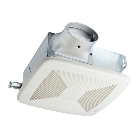
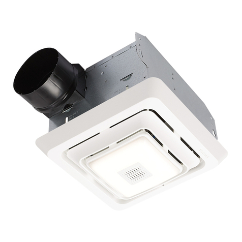
  9. Broan WD120NL User manual

Broan WD120NL User manual

Other Broan Fan manuals

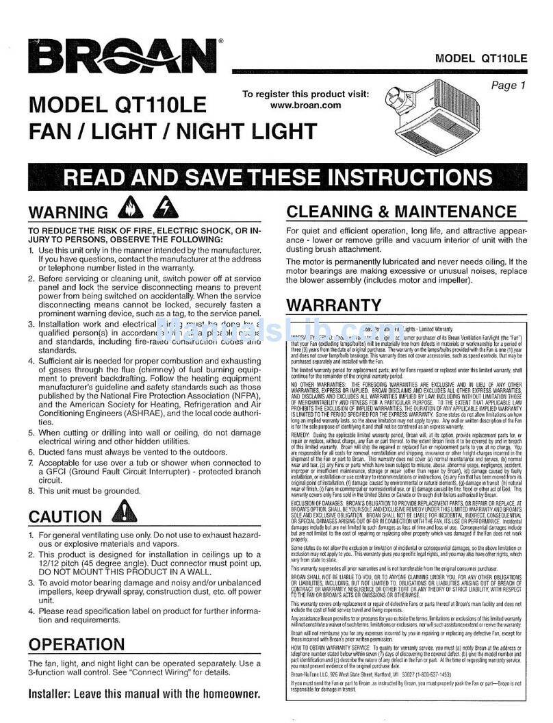
Broan 502 User manual

Broan

Broan 502 User manual

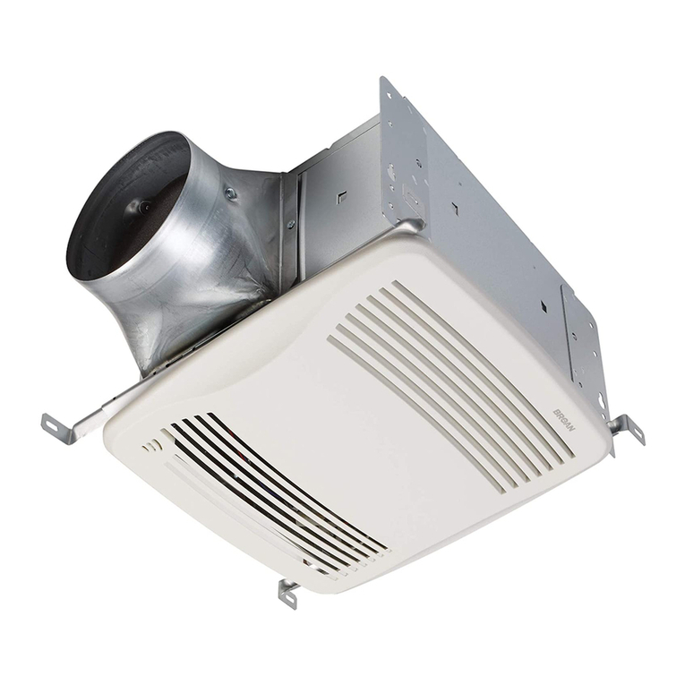
Broan QT80E User manual

Broan

Broan QT80E User manual

Broan ULTRA Pro RB80 User manual

Broan

Broan ULTRA Pro RB80 User manual

Broan 508 User manual

Broan

Broan 508 User manual

Broan ZB110L User manual

Broan

Broan ZB110L User manual

Broan 512N User manual

Broan

Broan 512N User manual

Broan 678 User manual

Broan

Broan 678 User manual

Broan XB 110 User manual

Broan

Broan XB 110 User manual

Broan 670 User manual

Broan

Broan 670 User manual

Broan 508 User manual

Broan

Broan 508 User manual

Broan CEILING VENTILATOR 683 User manual

Broan

Broan CEILING VENTILATOR 683 User manual

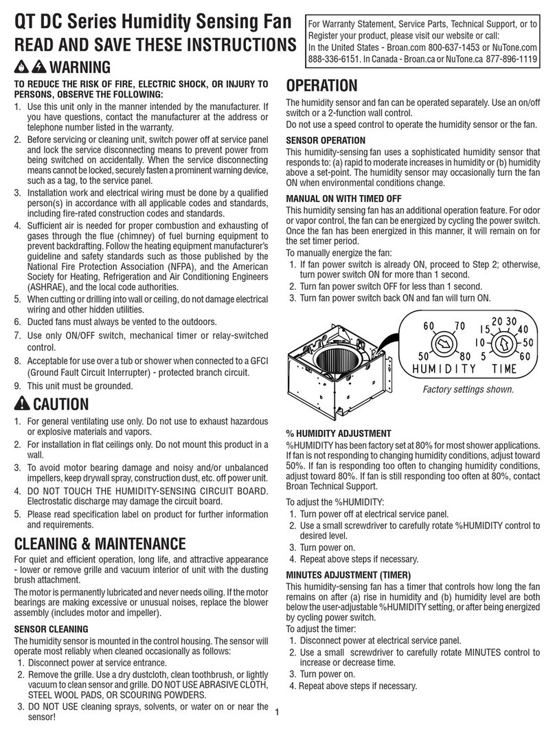
Broan QTR Series User manual

Broan

Broan QTR Series User manual

Broan SOLITAIRE Series User manual

Broan

Broan SOLITAIRE Series User manual

Broan ULTRA SILENT QTR070 User manual

Broan

Broan ULTRA SILENT QTR070 User manual

Broan QTR100FLT User manual

Broan

Broan QTR100FLT User manual

Broan ULTRA SILENT QTXE150 User manual

Broan

Broan ULTRA SILENT QTXE150 User manual

Broan Sensaire MS90 User manual

Broan

Broan Sensaire MS90 User manual

Broan 508N User manual

Broan

Broan 508N User manual

Broan QTR100FLT User manual

Broan

Broan QTR100FLT User manual

Broan 741BR Installation instructions

Broan

Broan 741BR Installation instructions

Broan 6714 User manual

Broan

Broan 6714 User manual

Broan ULTRA SILENT QTRE080R User manual

Broan

Broan ULTRA SILENT QTRE080R User manual

Broan 744SFL User manual

Broan

Broan 744SFL User manual

Broan B110H65RT Use and care manual

Broan

Broan B110H65RT Use and care manual

Popular Fan manuals by other brands

Minka Group minkaAire Wave F843 instruction manual

Minka Group

Minka Group minkaAire Wave F843 instruction manual

Airflow Adroit DV50 instruction manual

Airflow

Airflow Adroit DV50 instruction manual

Vornado 270 Series owner's guide

Vornado

Vornado 270 Series owner's guide

comfort air TH-10D instruction manual

comfort air

comfort air TH-10D instruction manual

Livoo DOM386 instruction manual

Livoo

Livoo DOM386 instruction manual

Holmes BLIZZARD HAOF-90 owner's guide

Holmes

Holmes BLIZZARD HAOF-90 owner's guide

Taurus GRECO 16 ELEGANCE manual

Taurus

Taurus GRECO 16 ELEGANCE manual

Quorum PINNACLE installation instructions

Quorum

Quorum PINNACLE installation instructions

Monte Carlo Fan Company 3DIR58RBD-V1 Owner's guide and installation manual

Monte Carlo Fan Company

Monte Carlo Fan Company 3DIR58RBD-V1 Owner's guide and installation manual

Craftmade UH52 installation guide

Craftmade

Craftmade UH52 installation guide

Jocel JVA030658 instruction manual

Jocel

Jocel JVA030658 instruction manual

MIKA MFB1211/GR user manual

MIKA

MIKA MFB1211/GR user manual

Harbor Breeze RLG52NWZ5L manual

Harbor Breeze

Harbor Breeze RLG52NWZ5L manual

Allen + Roth L1405 instruction manual

Allen + Roth

Allen + Roth L1405 instruction manual

ViM KUBAIR F400 ECOWATT Technical manual

ViM

ViM KUBAIR F400 ECOWATT Technical manual

HIDRIA R10R-56LPS-ES50B-04C10 user guide

HIDRIA

HIDRIA R10R-56LPS-ES50B-04C10 user guide

BLAUBERG Ventilatoren CENTRO-M 100 L user manual

BLAUBERG Ventilatoren

BLAUBERG Ventilatoren CENTRO-M 100 L user manual

Triangle Engineering HEAT BUSTER SPL Series owner's manual

Triangle Engineering

Triangle Engineering HEAT BUSTER SPL Series owner's manual

manuals.online logo
manuals.online logoBrands
  • About & Mission
  • Contact us
  • Privacy Policy
  • Terms and Conditions

Copyright 2025 Manuals.Online. All Rights Reserved.

79040117B
TECHNICAL PARAMETER
CA UT IO N
Before servicing or cleaning fan, switch power off at service panel. Lock or tag service panel to
prevent power from being switched on accidentally.
Never use chemicals to clean the fan.
Never submerse the fan motor or other electrical parts in water.
Do not immerse plastic parts in water over 60℃.
A. The grille, scroll and blower wheel can be discharged and cleaned using warm water or
kitchen detergent.
B. Gently clean fan, motor and interior of housing with a dusting brush.
MAINTENANCE
WD120NL
Ventilation Fan With Light
WIRING DIAGRAM
24/50 0
D120NL
W11036 6-1222x2
112
Ø100
120
Mod l
e
25
Fan Power
(W)
x
2×42 Ma .
Light Power
(W)
Sound
(dB)
Room Size
2
(m )
Pressure
(Pa)
Air Flow
3
(m /h)
Duct Size
(mm)
Ceiling Opening
(mm)
Voltage
(V/Hz)
Inner Connection
M
Blue
BrownBlack
Terminal Block
C1C2
Brown
Yellow/G reen
Black
White
Black
L1(Fan)
L2(Light)
Two Gang Switch
(Provided)
Outer Connection
Power Input 240V 50Hz
L
N
Black
http://www.Broan.com.au
Double Pole
Isolating Switch
(Not Provided)
WARRANTY CARD
WARRANTY
Two Years Limited Warranty:
Broan warrants the original consumers' purchase of its product(s) that such product(s) will be free from
defects in materials and workmanship for a period of two years from the date of original purchase.
During this two-year period, Broan will, at its option, repair or replace, without charge, any product or
part which is found to be defective under normal use and service.

THERE ARE NO OTHER WARRANTIES, EXPRESSED OR IMPLIED, INCLUDING BUT NOT LIMITED
TO THE LABOR COST OF REMOVING THE FAULTY PRODUCT(S), INSTALLING THE REPAIRED
OR REPLACED PRODUCT(S), OR FOR TRANSPORTING THE FAULTY PRODUCT(S) TO BROAN
OR AN AUTHORIZED SERVICE CENTRE.

This warranty does not cover: (a) countries outside of Australia and New Zealand (b) abnormal
maintenance and service (c) any products or parts which have been subject to misuse, negligence,
natural disasters or accidents (out of Broan’s control) improper maintenance or repair (other than by
Broan or an Authorized Service Centre) (d) faulty installation or installation contrary to recommended
installation instructions (e) any product(s) with a model number different from that being expressed in
the warranty card.

Claim Lodgement:
Please have your original receipt, model and serial number ready for lodgement of claim.
1. Call 1800 288 373. Warranty claims may be made weekdays from 9am to 5.30pm AEST, excluding
public holidays.
2. Quote your model number and serial number to our friendly staff.
3. Our staff will then provide you with a job number and assist you in your claim.
4. You will be required to email/post a copy of your original receipt for verification.
The benefits conferred by this warranty are in addition to all rights and remedies to a consumer under
the Commonwealth of Australia Competition and Consumer Act 2010 or other Commonwealth or State
legislation and this warranty does not purport to limit or exclude such rights and remedies.
Contact Information:
Nortek Australia Pty Ltd. 2/11-21 Forge Street, Blacktown, NSW, 2148, Australia
Email: info@nortekaustralia.com.au Telephone (+61) 1800 288 373
Customer Name:
Customer Contact Telephone:
Customer Address:
Product Model Number:
Date of Purchase:
Retailer Invoice Number:
READ AND SAVE THESE INSTRUCTIONS
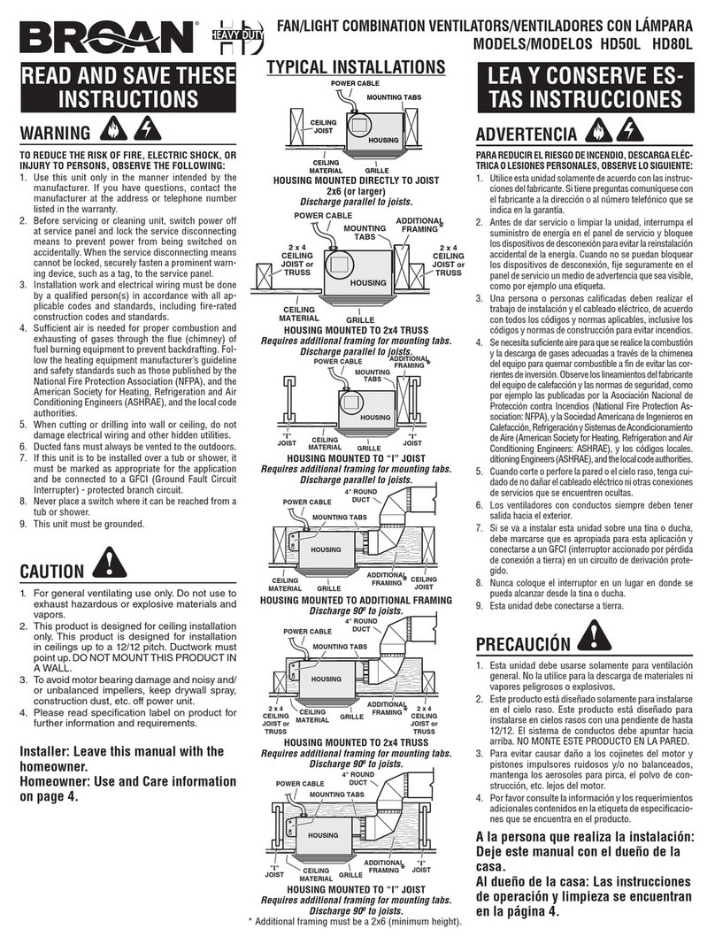
PRODUCT STRUCTURE AND DIMENSIONS
PACKING AND ACCESSORY LIST
2 4 m0 m
4 20 mm
130mm
Ø100mm
Ø337mm
115m m
INSTALL THE PRODUCT
Housing Assembly
Duct Connector
Glass Shade
PE Bag
Manual, Pass Card,
Screws T4x20(2pcs)
EPS
Accessory
Tube, Was herThreaded
Carton
Carton
Glass filler 2
Glass filler 1
Light Fitting
Filler(2 pcs)
Carton
42W Halogen Lamps(2pcs ),
Two Gang Switch
PE Bag
Light Base
Glass Shade Halogen Lamps(2pcs)
Washer
Motor Plate
SERVICE PARTS
Glass Shade
Washer
Halogen Lamps(2pcs) Light Fitting Bracket
Duct Connector
Connecting Bracket
Product packing list is shown below. Please check when you open the carton. If there is any
questions, please contact the distributor or service center.
5. Connect the light fitting electrical cable with
the plug provided. Using the threaded tube and
washer fix the light base to the light fitting
bracket. Install halogen lamps. Finally use
claws of light base to secure the glass shade.
6. Connect wire to relevant fuctions shown on
the switch.
Two Gang Switch
FAN
LIGHT
Switch Wiring Diagram
Threaded Tube
Light Base
Plug
Threaded Tube
Light Base
claw (3pcs)
Cardboard
1.
.
Use cardboard template to mark the correct
cut out size on the ceiling
2. Connect the flexible duc t to the duct
connector using tape or ties. Ensure t he
flexible duct is installed as straight as
possible. Insert duct con nector into
connecting bracket and fi x to ceiling using
screws (T4 x 20).
3. Remove the electrical connection box cover.
Insert the cables through the bush provided
and connect as indicated on the wiring
diagram ensuring the cables are captured
under the terminal screw. Replace cover.
Cut Out Size: 212mmx212m m
Duct Connector
Connecting Bracket
Connecting Bracket
Screws T4x20(2pcs)
Ceiling
Flexible D uct
Housing
Assembly
Co nne ct Place
Push In
Cover
4. Fix the long screw (#10-24) tightly onto the light
fitting bracket. Clip both sides of the light fitting
bracket under slots in fan housing assembly.
Use the short screw (#8-18) to fix bracket
securely.
Light Fitting Bracket
Long Screw #10-24
o
t
n
I
e
d
i
l
S
o
t
n
I
e
d
i
l
S
Light Fitting Bracket
Short Screw #8-18
Ceiling
Cables
Terminal Screw
Cables
Slots
Cardboard
Installation work must be
done by a qualified person
and installed securely.
Electrical wiring must be
done in accordance with all
appliance standards.
Convenient installat ion a nd
service
Install this unit in a f la t
ceiling only.
Prevent water backflow .
Please keep access opening.
Avoid the following cases of duct installation.
Provide suction hole(s).
The duct pipeline vented to
the outdoors must be
oblique, preventing rain or
frost backflow.
Duct
In Roo m
Outd oor
Angl e
Do not install in a place with
fumes and steam.
Ho using and m otor doesn’ t
to uch other c eiling
st ructure.
Prevent vibration and no ise
Less t han
Arou nd temp eratu re
40℃ Abo ve
50c m
The distance between fan
grille and floor must be
more than 2.3 meters.
Prevent accident
>2.3m
Do not install in a place with
high temperature.
CAUTION
Do no t use to exhaust hazard ous or explosiv e materials.
Whe n the product is co nnected to the power us ing a special power out let, the plug and p ower o utlet must meet t he
req uirements of AS3 000. The pow er outlet must be r ated at 10 amps and ensur e a reliable earth/gr ound connecti on.
Ins tall the produc t adjacent to the power o utlet.
Mou nt the fan or fan/l ight switch to meet the r equirements o f AS300 0.
A dama ged power cord should o nly be serviced b y a qual ified electri cian.
To avoi d motor bearing damag e and a noisy, un balanced impe ller, keep const ruction dust aw ay fro m these parts.
Chi ldren should be s upervised to ensure t hat they do not pla y with t he appliance.
The a ppliance is not i ntended for use by pers ons (includin g children) with redu ced physical, s ensory or menta l
cap abilities, or l ack of experien ce and k nowledge, unl ess they have bee n give n supervision o r instruction .
Do no t immerse the pro duct in water.
Ens ure that the appl iance is switched off from th e supply mains all-po le disconnect ion switch befo re replace the lamps.
An al l-pole discon nection switc h shall be mounted betw een the mains sup ply an d the wall switch o f the ap pliance. The
all -pole disconn ection switch s hall have a contact sep aration in all po les, providing full d isconnectio n from the mains
sup ply.
The a ppliance shal l, under no circumsta nces, be covere d with insulati ng matting and simila r material.