Bruker S1 TRACER User manual

Form 080/01
Complimentary Reference Material
This PDF has been made available as a complimentary service for you to assist in
evaluating this model for your testing requirements.
T G offers a wide range of test equipment solutions, from renting short to long
term, buying refurbished and purchasing new. Financing options, such as
Financial Rental, and Leasing are also available on application.
T G will assist if you are unsure whether this model will suit your requirements.
Call T G if you need to organise repair and/or calibrate your unit.
If you click on the “Click-to-Call” logo below, you can all us for FREE!
TMG Corporate Website TMG Products Website
Disclaimer:
All trademarks appearing within this PDF are trademarks of their respective owners.

BRUKER AXS HANDHELD
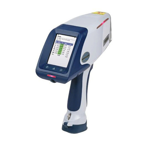
S1 TRACER Portable XRF Analyzer
User Manual
June 2008
415 North Quay • Kennewick, WA 99336
509 783 9850


Bruker AXS Handheld Inc S1 TRACER User Manual
Issued: 6/08
Supersedes: New
i
Caution: X-Ray Radiation
Bruker AXS Handheld manufactures an XRF analyzer, designated as the S1
TRACER, which contains an X ray tube. It is registered with the United States
Food and Drug Administration (FDA) Center for Devices and Radiological
Health. Specific safety requirements are provided for any purchased analyzer
which uses an X ray tube.
The S1 TRACER does not emit radiation when turned off. It is designed with fail
safe circuitry including switches, lamps, and interlocks to minimize the risk of
accidental exposure to the user during operation.
The safety features of the S1 TRACER have been verified by radiation safety
authorities. So long as there is no physical damage to the analyzer, there
should be no danger of exposure to radiation above permissible levels. If the
analyzer is damaged, store it in a secured area and contact Bruker AXS
Handheld at (800) 466 5323.
All XRF analyzers should be operated only by individuals who have completed
an approved radiation safety training program.
The red LED on the analyzer indicates that the X rays are on. Do not point the
analyzer at any person when the analyzer is activated. While measuring, make
sure that the analyzer is in contact with the sample material and that the entire
aperture, as well as the infrared (IR) sensor, is covered by the material. While
measuring, do not hold the sample material with your hand. eep your eyes
away from the nosepiece of the S1 TRACER while the trigger is pulled.
NOTE: Bruker XRF, Bruker AXS Handheld S1 TRACER, Bruker S1 TRACER and S1
TRACER, as used throughout this manual, refer specifically to the device
manufactured by Bruker AXS Handheld.
●
Note
Most countries and
states regulate the use
of X ray generating
devices such as XRF
analyzers. Regulations
for XRF analyzers vary
by location. Contact
your appropriate
agency for specific
information.
Note
Countries or states
may require
registration and/or
licensing. A fee
payment may be
required. If you are
planning to transport
a Bruker AXS
Handheld XRF analyzer
into another location,
contact the
appropriate authority
in that jurisdiction for
their particular
requirements before
transporting the
analyzer.

Bruker AXS Handheld Inc S1 TRACER User Manual
Issued: 6/08
Supersedes: New
ii
Important Notes for Bruker AXS Handheld XRF Analyzer
Customers
The Bruker S1 TRACER is classified as a portable hand held open beam X ray tube based
analytical X ray device. It is registered (Accession Number 0191097 01) with the United
States Food and Drug Administration (FDA) Center for Devices and Radiological Health.
Specific safety requirements are provided for any purschased analyzer which uses an X ray
tube.
This Bruker S1 TRACER User Manual provides training for Bruker S1 TRACER XRF analyzers.
The following four sections plus Appendix A contain important information on the safe use
of this XRF device. These are:
2. S1 TRACER Operator Radiation Safety Requirements
3. Principal Components of the S1 TRACER
4. Preparing the S1 TRACER for Use
5. Operation/General Purpose Measure
Appendix A. Basic Radiation Safety Information
Section 2. contains operator safety requirements specific to the Bruker S1 TRACER and
Appendix A contains basic radiation safety information.

Bruker AXS Handheld Inc S1 TRACER User Manual
Issued: 6/08
Supersedes: New
iii
Responsi ilities of the Customer
•Before using the S1 TRACER, all users shall read and understand the Operator
Radiation Safety Requirements (Section 2) and Basic Radiation Safety (Appendix A) of
this manual. Because the S1 TRACER produces X ray radiation, the analyzer shall only
be used by trained personnel who have passed the Bruker AXS Handheld Radiation
Safety Examination.
•Damage to a Bruker AXS Handheld analyzer may cause unnecessary radiation
exposure. If a Bruker XRF analyzer is damaged, immediately contact Bruker AXS
Handheld at (800) 466 5323 or (509) 783 9850.
•Disassembly of or tampering with any Bruker AXS Handheld XRF analyzer
component, except to replace the batteries or remove the handheld computer
(PDA), voids the warranty and compromises the integrity of the instrument. Harm or
serious injury may result in cases where disassembly or tampering has occurred.
•Comply with all instructions and labels provided with the S1 TRACER and do not
remove labels. Removal of any label will void the warranty.
•Test the S1 TRACER for correct operation of the ON/OFF mechanism every six months
and keep records of the test results. If the analyzer fails this test, call Bruker AXS
Handheld immediately for instructions.
•Maintain a record of S1 TRACER use, installation (if applicable), and any service to
shielding and/or containment mechanisms for two years or until ownership of the
analyzer is transferred or the analyzer is decommissioned.
•Report to the appropriate authority any possible damage to shielding and any loss or
theft of the analyzer. Do not abandon any XRF analyzer.
•Transfer the S1 TRACER only to persons specifically authorized to receive it and report
any transfer to the appropriate regulatory authority 15 to 30 days following the
transfer, if required. Report the transfer of the analyzer to Bruker AXS Handheld at
(800) 466 5323 or (509) 783 9850.

Bruker AXS Handheld Inc S1 TRACER User Manual
Issued: 6/08
Supersedes: New
iv
TABLE OF CONTENTS
Caution:
X-Ray Radiation.................................................................................................................................................................................. i
Important Notes for Bruker AXS Handheld XRF Analyzer Customers...........................................................................................................................ii
Responsibilities of the Customer .........................................................................................................................................................................................iii
1.
S1 TRACER Overview........................................................................................................................................................................................ 1
2.
S1 TRACER Operator Radiation Safety Requirements................................................................................................................................... 4
2.1
W
HAT IS
R
ADIATION
? ......................................................................................................................................................................... 4
2.2
X-R
AY
R
ADIATION FROM THE
S1
TRACER........................................................................................................................................ 5
2.3
H
AND
H
ELD
XRF
A
NALYZER
S
AFETY
D
ESIGN
................................................................................................................................... 6
2.4
S1
TRACER
R
ADIATION
P
ROFILE
.................................................................................................................................................... 11
2.5
U
SING THE
S1
TRACER
S
AFELY
...................................................................................................................................................... 15
2.6
R
ADIATION
S
AFETY
T
IPS FOR
U
SING THE
XRF
A
NALYZER
............................................................................................................... 15
2.7
C
ORRECT
S1
TRACER
P
OSITIONING
................................................................................................................................................ 18
2.8
I
N
C
ASE OF
E
MERGENCY
................................................................................................................................................................... 19
2.9
M
INOR
D
AMAGE
............................................................................................................................................................................... 19
2.10
M
AJOR
D
AMAGE
............................................................................................................................................................................... 19
2.11
L
OSS OR
T
HEFT
................................................................................................................................................................................. 19
2.12
L
ICENSE
/R
EGISTRATION
R
EQUIREMENTS
.......................................................................................................................................... 20
2.13
T
RANSPORTATION
R
EQUIREMENTS
................................................................................................................................................... 21
3.
Principal Components of the S1 TRACER...................................................................................................................................................... 22
3.1
P
RINCIPAL
S1
TRACER
C
OMPONENTS
............................................................................................................................................. 22
3.2
P
RINCIPAL
PDA
C
OMPONENTS
.......................................................................................................................................................... 23
3.3
P
RINCIPAL
V
ACUUM
P
UMP
C
OMPONENTS
......................................................................................................................................... 23
3.4
I
NCLUDED
A
CCESSORIES
................................................................................................................................................................... 24
3.5
A
DDITIONAL
A
VAILABLE
A
CCESSORIES
............................................................................................................................................ 27
3.6
O
PERATING
C
ONDITIONS OF THE
S1
TRACER.................................................................................................................................. 27
4.
Preparing the S1 TRACER for Use.................................................................................................................................................................. 29
4.1
P
OWERING THE
S1
TRACER
AND
PDA ............................................................................................................................................ 29
4.2
V
ACUUM
C
ONFIGURATION
................................................................................................................................................................ 37
4.3
T
ESTING
C
ONFIGURATION
................................................................................................................................................................. 39
4.4
S
TARTING THE
A
NALYZER
................................................................................................................................................................ 42
4.5
A
DJUSTING THE
PDA
B
ACKLIGHT
..................................................................................................................................................... 44
5.
Operation/General Purpose Measure............................................................................................................................................................... 45
5.1
S
TARTING THE
B
RUKER
S1
P
ROGRAM
................................................................................................................................................ 45
5.2
S
AMPLE
P
REPARATION
...................................................................................................................................................................... 49
5.3
A
NALYZER
S
ETTINGS
C
ONFIGURATION
............................................................................................................................................. 49
5.4
A
NALYSIS
M
ODES
............................................................................................................................................................................. 53
5.5
M
AKING
M
EASUREMENTS
................................................................................................................................................................. 56
5.6
V
IEWING
R
ESULTS AND
S
PECTRA
..................................................................................................................................................... 58
5.7
E
DITING
I
NFORMATION
..................................................................................................................................................................... 59
5.8
S
AVING
R
ESULTS AND
S
PECTRA
........................................................................................................................................................ 60
5.9
T
URNING OFF THE
A
NALYZER
........................................................................................................................................................... 60
5.10
V
IEWING AND
E
XPORTING
S
TORED
D
ATA
......................................................................................................................................... 60
5.11
C
HECKING
C
ALIBRATIONS
................................................................................................................................................................ 63
6.
Utilities Menu..................................................................................................................................................................................................... 65
6.1
V
IEW
R
EADINGS
................................................................................................................................................................................ 65
6.2
V
IEW
E
NERGIES
................................................................................................................................................................................. 66
Bruker AXS Handheld Inc S1 TRACER User Manual
Issued: 6/08
Supersedes: New
v
6.3
L
IBRARY
M
AINTENANCE
................................................................................................................................................................... 67
6.4
S
YSTEM
S
ETUP
.................................................................................................................................................................................. 72
7.
Troubleshooting ................................................................................................................................................................................................. 76
7.1
M
EASUREMENT WILL NOT START
...................................................................................................................................................... 76
7.2
C
AN
’
T FIND THE
B
RUKER
S1
PROGRAM ON THE
“S
TART
”
MENU
........................................................................................................ 76
7.3
T
HE
B
RUKER
S1
PROGRAM ON THE
PDA
WILL NOT START OR
“
LOCKS UP
”........................................................................................ 77
7.4
T
HE
PDA
IS DISPLAYING AN INCORRECT DATE AND
/
OR TIME
............................................................................................................ 78
7.5
T
HE VACUUM PUMP WILL NOT REACH
10
T
ORR OR LESS
................................................................................................................... 79
7.6
T
HE YELLOW LAMP ON THE CONTROL PANEL IS BLINKING
................................................................................................................ 79
7.7
T
HE RED LAMP ON THE CONTROL PANEL LOOKS UNEVEN
.................................................................................................................. 79
APPENDIX A: BASIC RADIATION SAFETY INFORMATION ................................................................................................................................. 80
A.1
W
HAT IS
R
ADIATION
? ....................................................................................................................................................................... 80
A.2
T
HE
C
OMPOSITION OF
M
ATTER
......................................................................................................................................................... 81
A.3
E
LECTRICAL
C
HARGE OF THE
A
TOM
................................................................................................................................................. 83
A.4
T
HE
S
TABILITY OF THE
A
TOM
........................................................................................................................................................... 84
A.5
R
ADIATION
T
ERMINOLOGY
............................................................................................................................................................... 84
A.6
T
YPES OF
R
ADIATION
........................................................................................................................................................................ 85
A.7
U
NITS FOR
M
EASURING
R
ADIATION
.................................................................................................................................................. 89
A.8
S
OURCES OF
R
ADIATION
................................................................................................................................................................... 91
A.9
B
IOLOGICAL
E
FFECTS OF
R
ADIATION
................................................................................................................................................ 96
A.10
R
ADIATION
D
OSE
L
IMITS
................................................................................................................................................................ 100
A.11
M
EASURING
R
ADIATION
................................................................................................................................................................. 102
A.12
R
EDUCING
E
XPOSURE
(ALARA
C
ONCEPT
)..................................................................................................................................... 104

Bruker AXS Handheld Inc S1 TRACER User Manual
Issued: 6/08
Supersedes: New
1
1. S1 TRACER Overview
The Bruker S1 TRACER, produced by Bruker AXS Handheld, is a portable, wide range elemental
analyzer intended for a variety of applications, including alloys, environmental analysis, and
hazardous substance detection. It provides a method for chemical analysis or material identification
(sorting) directly for materials of various forms. The S1 TRACER is based on energy dispersive X ray
fluorescence technology (ED XRF) and uses an X ray tube as its excitation source. Tubes may use a
bulk Rhodium (Rh) or Silver (Ag) target, depending on the purchased configuration. The instrument
contains a high resolution, Peltier cooled, Silicon PIN (Si PIN) diode detector.
The S1 TRACER is a fully field portable analyzer with an integrated PDA (Personal Digital Assistant)
computer (see Figure 1.1). The removable PDA provides the user interface for operating the
instrument and contains the BrukerS1 analytical program. This program enables the user to select
analytical modes, view spectra, and save data. The display is a color touch screen (TFT), which can be
operated with either a fingertip or the provided stylus. The instrument is factory calibrated for
measurements of:
•Aluminum alloys
•Titanium alloys
•Low alloy steels
•Stainless steels
•Tool steels
•Nickel alloys
•Cobalt alloys
•Copper alloys
Figure 1.1: Portable configuration of the S1 TRACER

Bruker AXS Handheld Inc S1 TRACER User Manual
Issued: 6/08
Supersedes: New
2
The S1 TRACER has an internal mechanism called a filter wheel which inserts various filters into the
primary X ray beam. The filter wheel contains five filter positions; one position contains no filter
material. Selection of a particular filter is completely automatic and depends on the test method
chosen in the BrukerS1 program (as described in section 5.3.4). When the “Method” setting is
changed, the filter wheel can be heard briefly spinning inside of the analyzer. The filter wheel is also
heard shortly after the analyzer power has been turned on. This sound is normal and indicates that
the analyzer is working properly.
In some cases, it may be more convenient to use the S1 TRACER in a stationary, bench top
configuration. Figure 1.2 shows the S1 TRACER in the stand provided. There are grooves in the body
and the handle which slide into the stand.
Figure 1.2: Bench top configuration Figure 1.3: Vacuum configuration

Bruker AXS Handheld Inc S1 TRACER User Manual
Issued: 6/08
Supersedes: New
3
When aluminum or titanium alloys are to be examined, the S1 TRACER should be used in vacuum
mode. The vacuum pump attaches to the instrument with the provided tubing as shown in Figure 1.3.
The slide vent valve vents the system when vacuum is not in use to prevent damage to the highly
sensitive Si Pin detector. The clip on window protector must be removed when in vacuum mode to
obtain accurate readings.
Note: When the user selects an aluminum or titanium method in the BrukerS1 program, the software
prompts the user to connect the vacuum pump. Additional information on selection of vacuum mode
is contained in sections 4.2 and 5.3.4.
The S1 TRACER analyzer and the vacuum pump are battery operated. They may also be operated
from A/C power. Note that for bench top operation, the instrument can be used with battery or A/C
(line voltage) power.
An optional PC can also be puchased with the S1 TRACER when it is used for special applications, such
as Art & Conservation
.

Bruker AXS Handheld Inc S1 TRACER User Manual
Issued: 6/08
Supersedes: New
4
2. S1 TRACER Operator Radiation Safety Requirements
2.1
2.12.1
2.1 What is Radiation?
•The term radiation is used with all forms of energy—light, X rays, radar, microwaves, and
more. For the purpose of this manual, radiation refers to invisible waves or particles of
energy from X ray tubes.
•High levels of radiation may pose a danger to living tissue because it has the potential
to damage and/or alter the chemical structure of cells. This could result in various levels
of illness (i.e. mild to severe).
•This section of the manual provides a basic understanding of radiation characteristics.
This should help in preventing unnecessary radiation exposure to S1 TRACER users and
persons nearby. The concepts have been simplified to give a basic picture of what
radiation is and how it applies to operators of the S1 TRACER XRF analyzer.
•Sections 2.2 2.4 characterize the S1 Tracer safety features and controls and provide
specific radiation profiles for the S1 TRACER analyzer.
•The user of a S1 TRACER XRF analyzer should study Appendix A to better understand the
nature of radiation and how to be safe using handheld XRF analyzers. Appendix A will also
provide perspective as to the exposure levels associated with the equipment.

Bruker AXS Handheld Inc S1 TRACER User Manual
Issued: 6/08
Supersedes: New
5
2.2
2.22.2
2.2 X-Ray Radiation from the S1 TRACER
X rays are emitted at approximately a 53° angle from the aperture to the user’s left (as viewed
from the user’s perspective), shown in figure 2.1.
Figure 2.1: Emission of X-rays from the aperture
Radiation Scatter
Radiation scatter is produced whenever an absorbing material is directly irradiated from a
nearby source. The atoms within the material become temporarily excited, producing X rays
before becoming stable again. This process, called X ray fluorescence (XRF), is the principle of
operation of the S1 TRACER XRF analyzer.
The X ray tube within the S1 TRACER is used to irradiate a chosen material at very close range
with a narrow, collimated beam. The X rays from the tube excite the atoms of the material,
which then produce secondary X rays that scatter in random directions. Hence, the term
radiation scatter.
Backscatter
The S1 TRACER generates spectrum data by analyzing the specific secondary X ray energies that
travel from the sample under test to the instrument detector. Because X rays travel in random
directions, it is possible for an X ray to miss the detector and be scattered in the direction of the
operator. This is referred to as backscatter.
X
-
RAYS
IR Sensor

Bruker AXS Handheld Inc S1 TRACER User Manual
Issued: 6/08
Supersedes: New
6
Although the S1 TRACER is specifically designed to limit backscatter, there is always the
possibility that a small number of X rays may scatter beyond the detector. To ensure safe
operation of the system, it is vital that the operator understands the radiation field. The
radiation profiles provided in Figures 2.8 and 2.9 illustrate the radiation field intensity for the S1
TRACER. The Radiation Profile section contains the details on measurements of the radiation
field. The profiles should be studied carefully by anyone who operates the S1 TRACER, in order
to better understand and apply the practices of ALARA using time, distance and shielding.
2.3
2.32.3
2.3 Hand Held XRF Analyzer Safety Design
The Bruker S1 TRACER series XRF analyzers employ a miniature X ray tube instead of a
radioactive material to generate the X rays. The general construction and the safety features
described in this manual are the same for all S1 TRACER models.
Bruker AXS Handheld designed this hand held X-ray tube analyzer to conform to 21 CFR
1020.40 safety requirements for cabinet (i.e. closed beam) X-rays systems, with the exception
of providing a totally enclosed beam.
Note: To prevent the operator from being directly exposed to the open X ray beam, extensive
safety circuit requirements including switches and failsafe lamps have been incorporated.
The S1 TRACER series portable XRF analyzers were tested by TUV SÜD against safety
requirements of IEC 61010 1, “Safety Requirements for Electrical Equipment for Measurement,
Control, and Laboratory User, Part I General Requirements.” The S1 TRACER passed the ionizing
radiation leakage requirements in IEC 61010 1, section 12.2.1 of <1 μSv/hr (<0.1 mrem/hr) at
100 mm. Since the instruments passed all of the safety requirements, the device was afforded
the
C
TUV
US
license, CB Global Scheme, and the general CE marks. The license requires periodic
production audits by TUV SÜD. See the S1 TRACER Safety Logic Circuit section for discussion on
the warning lamps, failsafe features, and labeling that has been incorporated to provide a high
level of protection to the operator.
The S1 TRACER is a hand held (4 lb.) X ray fluorescence (XRF) analyzer used as an analytical X ray
system. It employs a 4 watt, miniature (<15 mm diameter and <75 mm long) X ray tube operated
with an acceleration voltage range of 6 to 40 kV and a current range of 0.05 20 μA, (the
maximum high voltage available at 20 μA is 15 kV). In some cases, allowable ranges for X ray
tube voltage and current may be different to comply with local regulations. The tube target is
dependent on the intended application and may contain target material such as Rh, Ag or Re.
The X ray tube and high voltage (HV) power supply are sealed in a fluid filled assembly. The X ray
tube is shielded by a variety of materials to minimize any stray X ray radiation. This is mounted in
the XRF housing and the XRF housing is closed using tamper proof fasteners.
The S1 TRACER X ray beam is collimated through an aperture that is approximately 0.14 inches
(3.5 mm) in diameter. The aperture is part of the beam collimator assembly. The radiation

Bruker AXS Handheld Inc S1 TRACER User Manual
Issued: 6/08
Supersedes: New
7
profiles illustrated in Figures 2.8 and 2.9 illustrate the effectiveness of the design to limit X ray
emission to primarily that which passes through the aperture. See the Radiation Profile Section
for discussion of the radiation profile measurements.
2.3.1
2.3.12.3.1
2.3.1 Safety Logic Circ
Safety Logic CircSafety Logic Circ
Safety Logic Circuit, Indicator
uit, Indicator uit, Indicator
uit, Indicator Lamp
LampLamp
Lamps and Warning La els
s and Warning La els s and Warning La els
s and Warning La els
The S1 TRACER analyzer is designed with a Failsafe Safety System to prevent inadvertent
operation of the analyzer. The safety system for the S1 TRACER analyzer consists of a key
switch, password protection, two (2) failsafe LED indicator lamps, a trigger to activate X
rays, an infrared proximity sensor to verify close proximity of a test sample, and a low count
rate detection safety shutoff. The function of each of the S1 TRACER’s safety features is
described below:
•Primary Power Safety ey Switch – A keyed main power switch (Figure 2.3) is
employed to control power to all components. The key switch must be turned on
before any other actions can be initiated.
•Software Password Protection – BrukerS1 software on the companion PDA must be
running for the analyzer to generate X rays. Upon launching the BrukerS1 PDA
software, a user password must be correctly entered to enable the analyzer to
generate X rays.

Bruker AXS Handheld Inc S1 TRACER User Manual
Issued: 6/08
Supersedes: New
8
•Software X-ray Radiation Warning – Presuming that the correct password has been
entered, the PDA software displays a black and yellow X ray Radiation Warning
symbol and a text warning for 15 seconds. No user input is accepted during the time
the X ray Radiation Warning is displayed.
•Yellow Power On Indicator Lamp – When the key switch is turned on, the yellow
lamp (Figure 2.3) will illuminate, indicating that the analyzer is powered on. The lamp
incorporates redundant LED elements for increased reliability.
If the instrument microprocessors detect a malfunction in the instrument, the yellow lamp
flashes to alert the user. The redundant LED segments are incorporated in such a way that if
either of the LED elements fails, generation of X rays is disabled.
•Operator Trigger Interlock– When the trigger style switch is pulled, X rays are
generated if the rest of the safety circuit has been satisfied. The switch is spring
loaded and must be held in during measurements. If the switch is inadvertently
released, the spring mechanism will return the switch to its idle position and stop X
ray generation.
•Infrared (IR) Proximity Sensor – The IR proximity sensor is used to confirm that the
instrument has been placed against a sample. The sensor is located in the instrument
nosepiece near the tube/detector opening. If the nosepiece is removed from the
sample by a distance greater than 38mm (~1.5”) the IR proximity sensor will stop X
ray generation. The exact distance is somewhat dependent on the sample material
being tested.
•Red X-ray On Indicator Lamp – When the trigger is pulled and the infrared sensor is
engaged, the red lamp (Figure 2.3) will illuminate, indicating the generation of X
rays. The lamp incorporates redundant LED elements for increased reliability. If
either of the red LED elements fail, X rays cannot not be generated.
•Low Count Rate Detection Safety Shutoff – While X rays are being generated, the S1
TRACER microprocessor continually monitors raw count rate from the detector. If at
any time during the measurement, the raw count rate falls below 500 counts per
second, the microprocessor will stop X ray generation since this indicates that no
sample is in place. Should this occur, the operator must release the trigger and then
re start the test.

Bruker AXS Handheld Inc S1 TRACER User Manual
Issued: 6/08
Supersedes: New
9
2.3.2
2.3.22.3.2
2.3.2 S1 TRACER
S1 TRACERS1 TRACER
S1 TRACER XRF Safety Warning La els
XRF Safety Warning La els XRF Safety Warning La els
XRF Safety Warning La els
The S1 TRACER has safety warning labels to alert the user and/or identify the functions of
the controls. These labels are described below.
•To the right of the power (key switch) part of the analyzer (Figure 2.2) is a sign as
follows:
Figure 2.2: Caution radiation sign
•The control panel of the analyzer is labeled as illustrated in Figure 2.3
Figure 2.3: S1 TRACER control panel and indicator lamps
•The yellow lamp, when illuminated, indicates power is applied to the analyzer.
•The red lamp, when illuminated, indicates that X rays are being generated.
•The power (key switch) is labeled with an international power On/Off symbol.
Dual yellow LED
indicates power on
(solid) or error
(blinking)
Dual red LED
indicates X rays on
Power
On/Off
Power safety key
switch

Bruker AXS Handheld Inc S1 TRACER User Manual
Issued: 6/08
Supersedes: New
10
•The vacuum window over the examination window carries a label with an X ray warning
(Figure 2.4)
Figure 2.4: Vacuum window and X-ray warning label
•An X ray warning label is located near the nosepiece of the analyzer (Figure 2.5)
Figure 2.5: X-ray warning label near nosepiece of analyzer
•On the clip on window protector that covers the analyzer nose (Figure 2.6) are two signs:
Figure 2.6: Clip-on window protector warning sign

Bruker AXS Handheld Inc S1 TRACER User Manual
Issued: 6/08
Supersedes: New
11
•A metal manufacturer’s plate (Figure 2.7) is mounted under the analyzer housing near the
handle. In countries other than the USA, this label may be different based on local
regulatory requirements.
Figure 2.7: Instrument base caution sign
2.4
2.42.4
2.4 S1 TRACER Radiation Profile
The radiation profile of the S1 TRACER shown in Figures 2.8 and 2.9 are for normal operating
conditions. These readings show the radiation background around the instrument in all
directions. These values were obtained using a Bicron Low Energy Micro Rem ion chamber.
These measurements indicate that the dose rate at 10 cm from any accessible surface was lower
than 5.0 μSv/hr (less than 50 μrem/hr).
In Figure 2.8, measurements were made at 40 kV and 10 μA (the maximum current/voltage
permitted) with the Ti/Al filter in place.
In Figure 2.9, measurements were made at 15 kV and 20 μA without the Ti/Al filter.

Bruker AXS Handheld Inc S1 TRACER User Manual
Issued: 6/08
Supersedes: New
12
Radiation Profile
(For 40 kV 10 µA, Duplex 2205 sample in beam)
Reading (µrem/hr) Reading (µrem/hr)
A 2 G 1
B bkgnd H bkgnd
C bkgnd I bkgnd
D 2 J 1
E bkgnd K bkgnd
F bkgnd L bkgnd
Figure 2.8 Dose rates for the S1 TRACER normal operation configuration. Readings are in
μ
rem/hr.
All other locations on side, top, bottom and back of the analyzer are background (bkgd). Readings
taken with a Bicron Model RSO 50 E low energy ion chamber survey instrument. Reference
distances were measured from the effective center of the detector to the surface of the analyzer or
sample. The indicated readings were the maximum noted for the distances and locations. Each
reading was taken over a one minute period with the analyzer operating at approximately 10 μA and
40 kV, with a Ti/Al filter.
Note: dose rates will vary based on current, energy, sample, target, collimator and windows.
Table of contents
Other Bruker Measuring Instrument manuals

Bruker
Bruker minispec mq20 User manual

Bruker
Bruker DektakXT Manual

Bruker
Bruker CTX User manual

Bruker
Bruker VERTEX 70v User manual

Bruker
Bruker CTX User manual

Bruker
Bruker BMS User manual

Bruker
Bruker minispec LF Series User manual

Bruker
Bruker D8 Discover Manual

Bruker
Bruker ultraflex III User manual

Bruker
Bruker DektakXT User manual
Popular Measuring Instrument manuals by other brands

GTCO CalComp
GTCO CalComp Roll-Up III quick start

Bopp & Reuther
Bopp & Reuther Vortex VTX3 K i Ex Supplementary instructions

Autel
Autel MaxiScan MS309 manual

Burkert
Burkert S020 operating instructions

Vanguard Instruments
Vanguard Instruments CT-8000 S3 user manual

Shimadzu
Shimadzu UV-1800 instruction manual