344642 - 344643
31/07/2018ST-00000361-
B
A B C
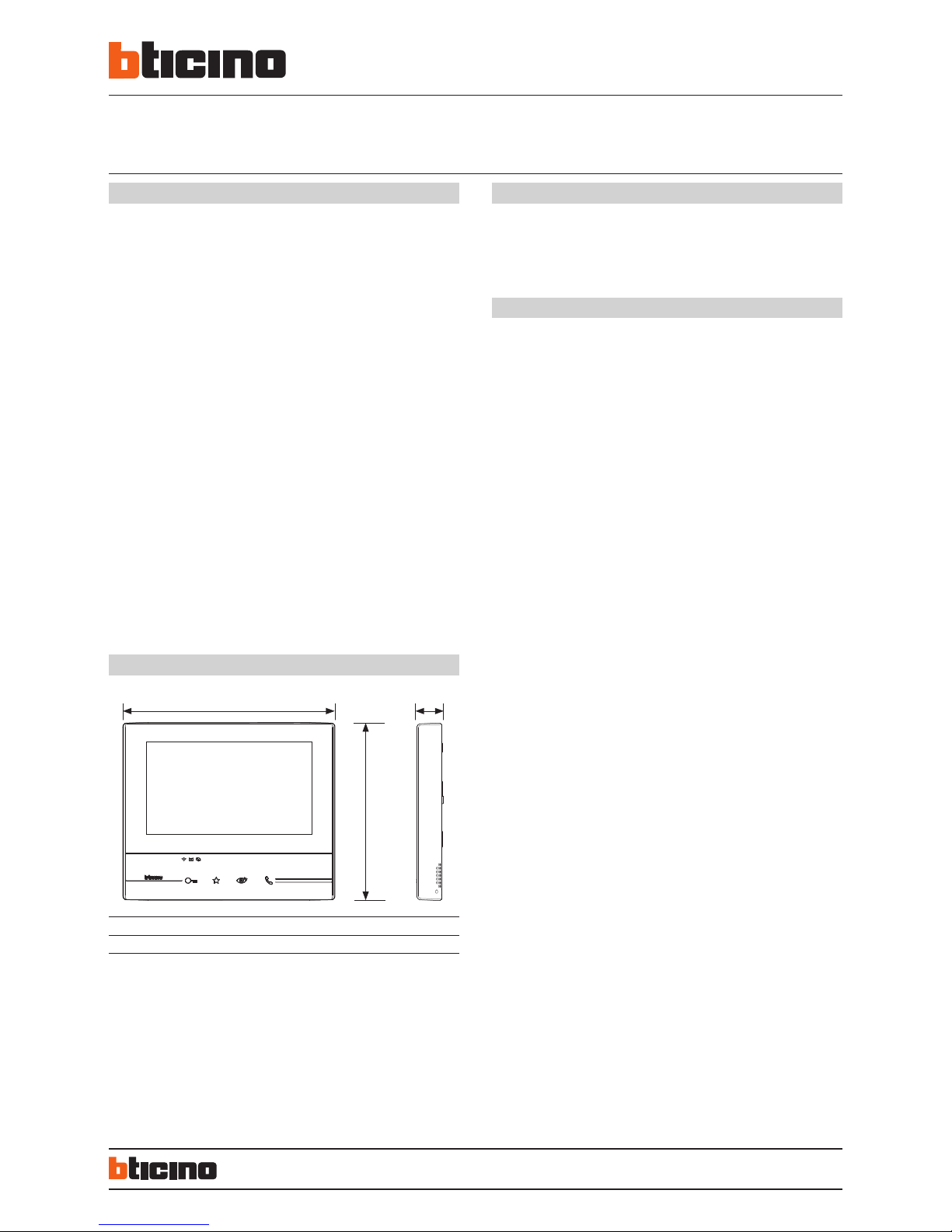
194 mm 162 mm 22 mm
A C
EN
2 WIRE/Wi-Fi handsfree video internal unit with inductive loop, 7”Touch Screen
LCD display and video door entry answering machine with call audio/video
memory – light and dark finish.
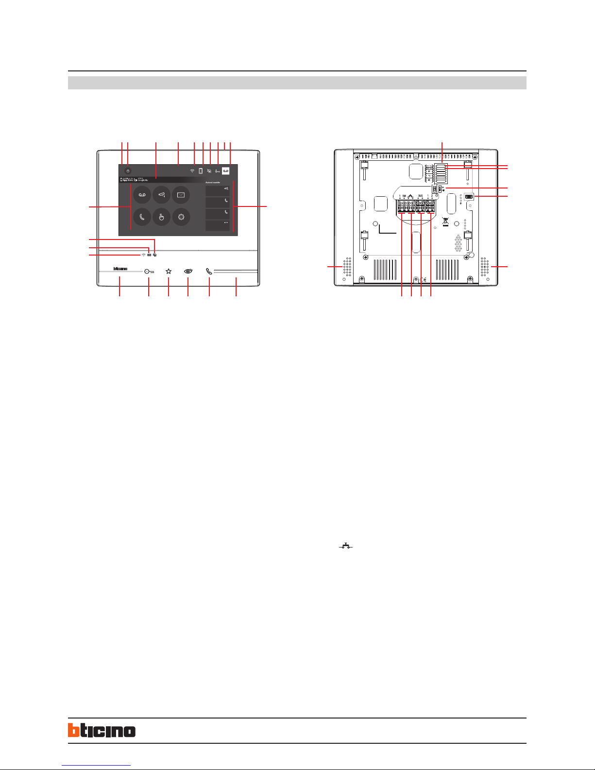
It has capacity keys for the control of the main video door entry functions: door lock
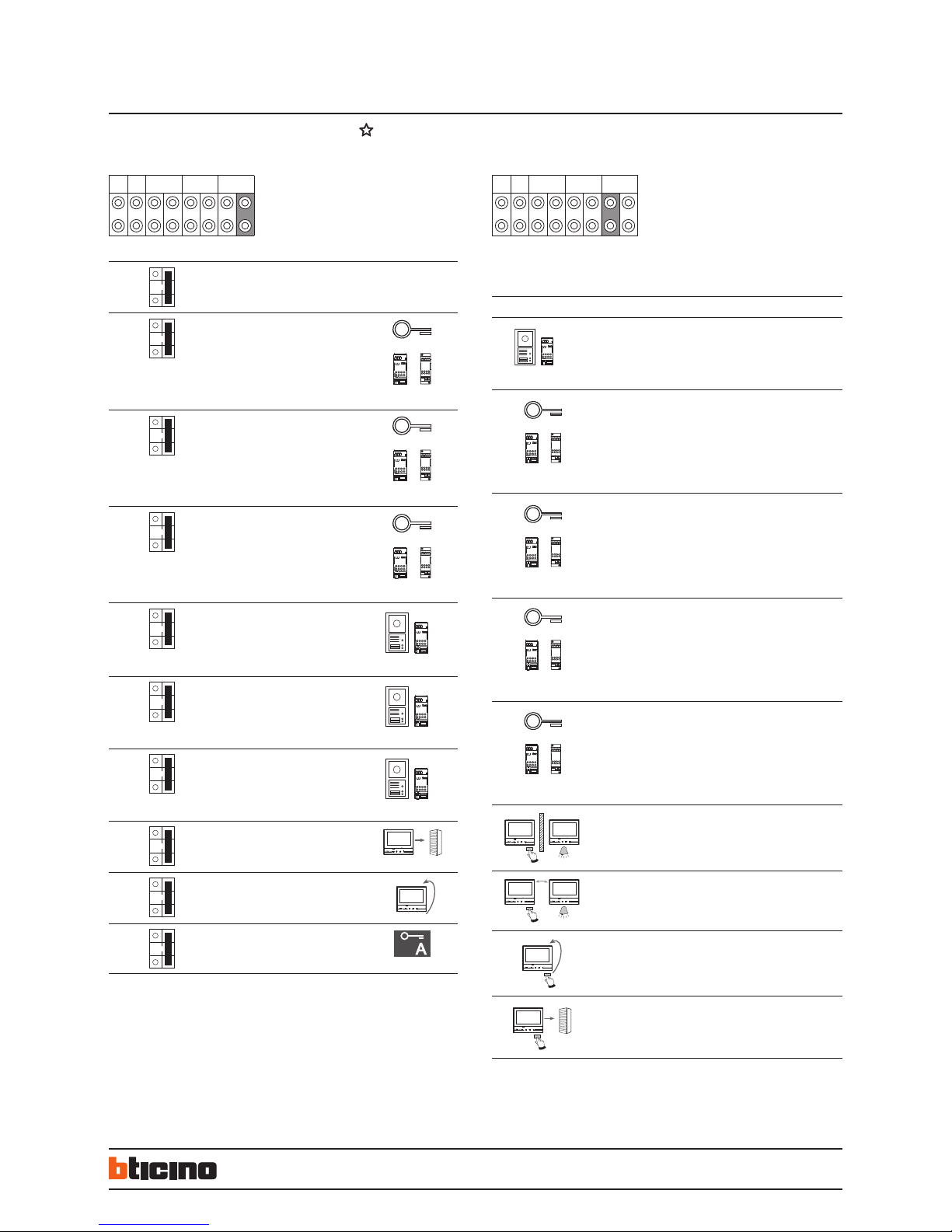
release, handsfree connection, entrance panel/scrolling activation and Favorite key
(can be configured to activate the quick actions most frequently used - eg: staircase
lights control, Intercom, additional activations).
Tactile guide for easy access to door lock and handsfree capacitive connection keys.
LEDs used for: call exclusion, notification of messages from switchboard, Wi-Fi and
memo. Access to adjustments and functions using the touch display.
MEMO function - for writing using the keypad, or for voice recording of messages
and/or notes for the other residents of the apartment (e.g.: call plumber, do the
shopping, etc.).
Possibility of voice communication with the switchboard - if present in the system
- after a specific call.
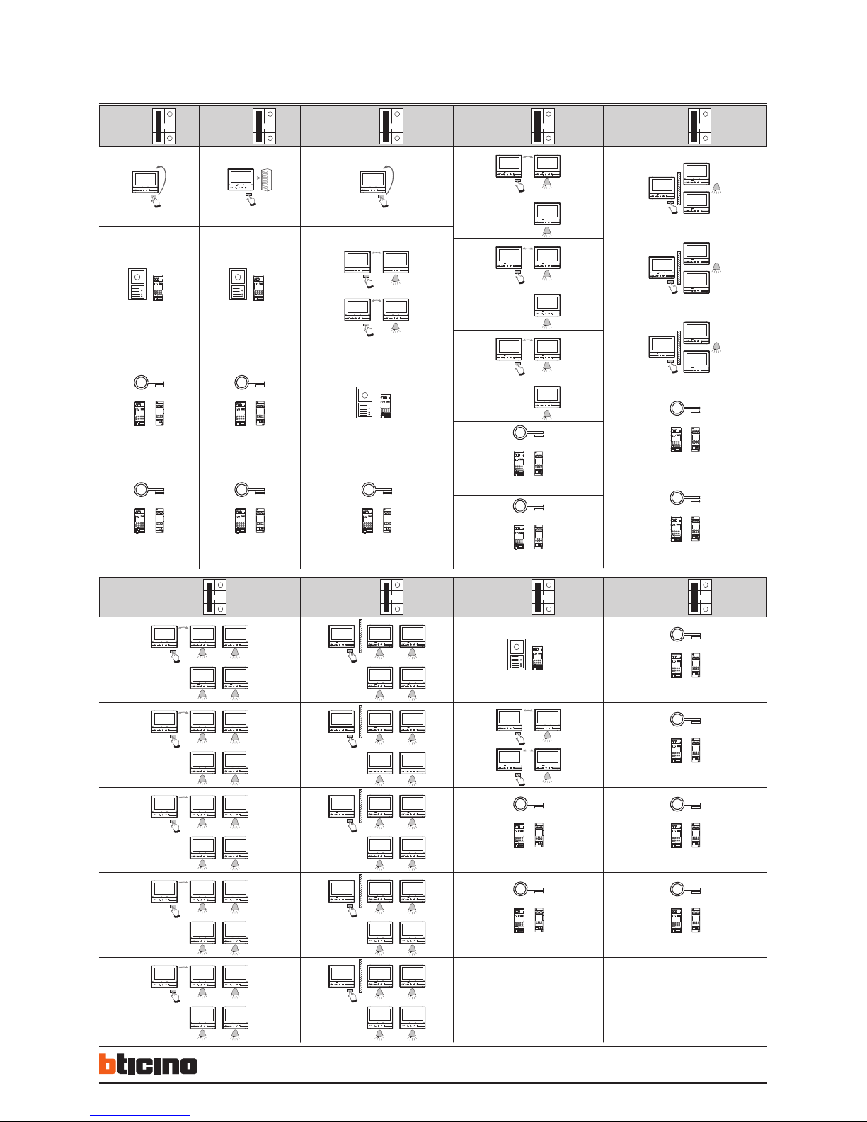
The device must be configured by physically connecting the configurators, or
using the menu, which will give better possibilities of customisation of associated
functions and texts.
Also, thanks to the Wi-Fi connection, you can associate the video internal unit
to the Door Entry App (available for Android and iOS). You can manage the main
video internal unit functions (receiving calls, opening the door lock, activating the
entrance panel/scrolling, FWR updating and additional activations) from the App.
Compatibility with:
- 2 wire Switchboard 346310
- Interfaces 349410, 346850, 346851, 346150
Description
344632 Table-top support.
336803 Cable for connection in the table top installation.
346020 2 DIN additional power supply.
Related items
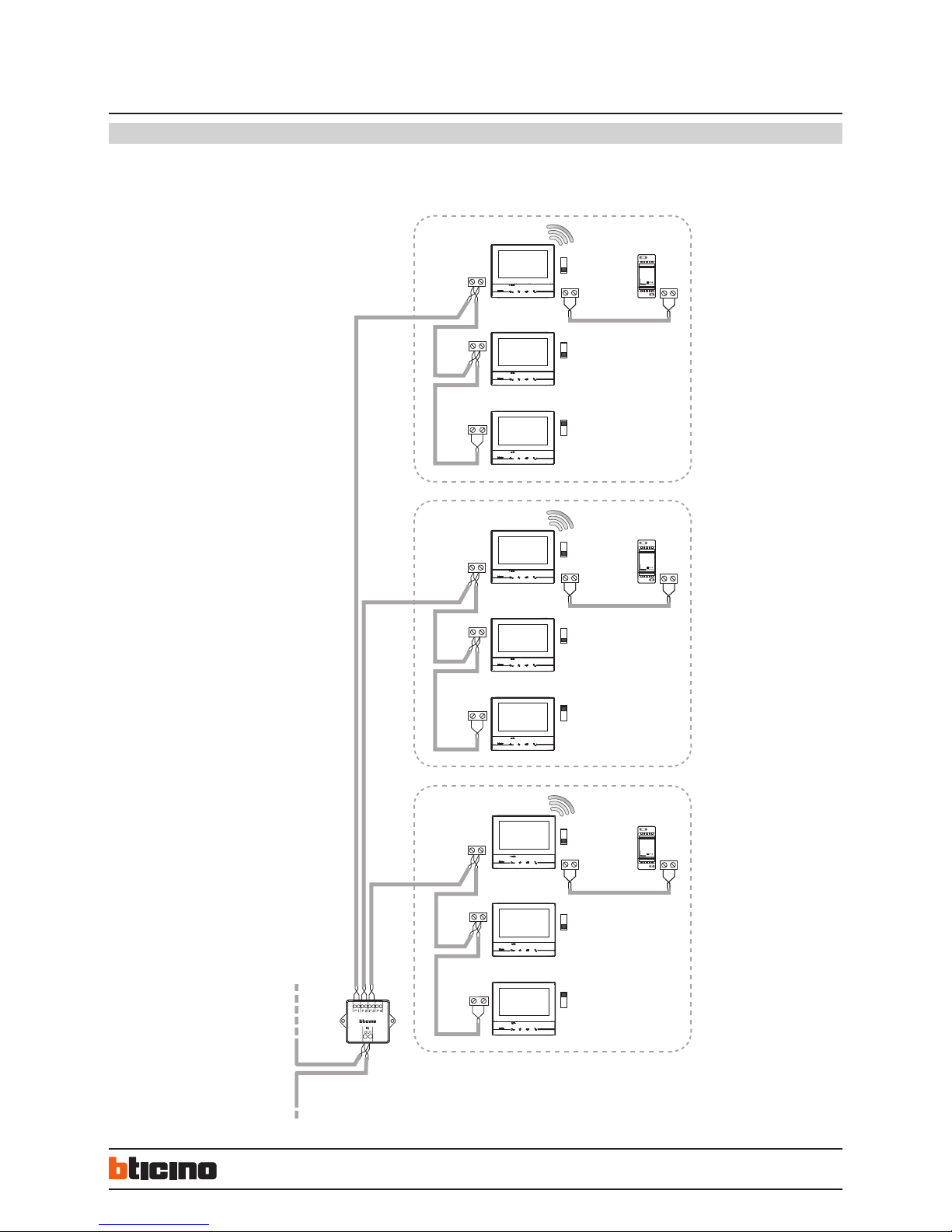
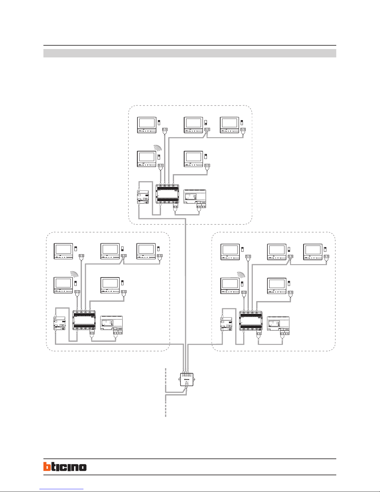
CLASSE 300X13E
Touch Screen handsfree video internal units
with Wi-Fi
Power supply from SCS BUS: 18 – 27 Vdc
Maximum SCS absorption in Stand by: 110 mA
Maximum SCS absorption in operation: 400 mA
Additional power supply of clamp 1 – 2: 27 Vdc
Maximum absorption from clamp 1 – 2: 250 mA
Operating temperature: 5 – 40 °C
The Classe 300X video internal unit must be connected to a Wi-Fi network with the
following features:
– IEEE 802.11 b/g/n (2,4 GHz) 13 channels
– Encrypting and authentication methods supported:
- OPEN WPA-PSK networks
- TKIP WPA2-PSK included
- included AES WEP 64 bits (ASCII 5 figure or hexadecimal 10 figure codes)
- WEP 128 bits (ASCII 13 figure or hexadecimal 26 figure codes)
- WPS authentication (supported for WPA2-PSK)
Ports and protocols used by Classe300X and DoorEntryApp.
- 5061 SIP (used by Classe 300X)
- 5228 SIP (used by the mobile app)
- 0 to 65000 UDP (runtime negotiated for multimedia streaming)
- 80/443 HTTP / HTTPS
Note:
a domestic Wi-Fi with internet access is needed for the connection between the
Classe300X13E video internal unit and the smartphone.
To use the service, the Customer must acquire the technical equipment which allows
access to the Internet, on the basis of an agreement made by the Customer himself with
an ISP (Internet Service Provider). BTicino plays no part in this.
The Customer must install the App on his smartphone so that he can use some services
which BTicino supplies as extras to the normal basic functions of the Classe300X13E.
The services offered by means of the APP require being able to interact with
Classe300X13E remotely and through the Internet.
In these cases the integration and good working between Classe300X13E and APP may
depend on:
quality of the Wi-Fi signal
type of access contract to the home Internet
type of data contract on the smartphone
When one of these 3 elements does not conform with the specifications required for
product operation, BTicino accepts no responsibility for any faults.
The product in fact supports a VoIP streaming system. You must therefore check with
your smartphone data network contract that it does not block it.
We would like to inform you that the service provided by BTicino by means of remote use
via the APP involves the use of data. The cost linked to data usage depends on the type
of contract which the customer has with his ISP (Internet Service Provider) and is solely
the customer’s responsibility.
Technical data
Dimensional data