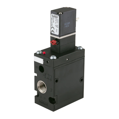
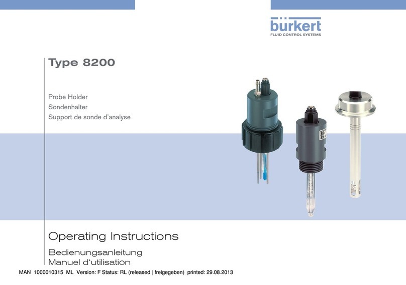
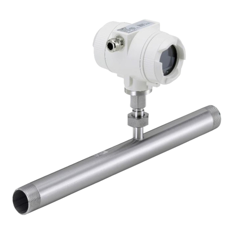
Burkert MP05 User manual

Type 0450
Block Assembly
Aluminium baseplate Type MP05
Mehrfachblock
Aluminiumgrundplatte Type MP05
bloc multiple
Plaque de montage en aluminium Type MP05
Operating Instructions
Bedienungsanleitung
Instructions de Service

We reserve the right to make technical changes without notice.
Technische Änderungen vorbehalten.
Sous resérve de modification techniques.
© 2000 Bürkert Werke GmbH & Co. KG
Operating Instructions 0507/04_EU-ML_00803843

8640-0450 - 1
CONTENTS
english
Contents:
GENERAL NOTES.................................................................................................................................................................................................................................... 3
Symbols ......................................................................................................................................................................................................................................................
4
Safety notes.............................................................................................................................................................................................................................................
4
Scope of delivery ...........................................................................................................................................................................................................................
5
Warranty conditions ..................................................................................................................................................................................................................
5
TECHNICAL DATA ................................................................................................................................................................................................................................... 7
Valve construction........................................................................................................................................................................................................................ 8
Method of functioning of valves Type 0450 .............................................................................................................................................
8
Media ...............................................................................................................................................................................................................................................................
8
Electrical connection ...............................................................................................................................................................................................................
9
ASSEMBLY AND COMMISSIONING ...................................................................................................................................................................... 11
Measures to be taken before commissioning.................................................................................................................................. 12
Assembly and commissioning .............................................................................................................................................................................. 12
Construction of block assemblies with aluminium baseplate MP 05 .............................................................. 13
Assembly of valve Type 04540 on the aluminium baseplate ...................................................................................... 14
Disassembly of valve Type 04540 from the aluminium baseplate ........................................................................ 14
Fixing the valve block to a standard rail.................................................................................................................................................. 14
Fixing the valve block to the wall ......................................................................................................................................................................... 14
MAINTENANCE AND TROUBLE SHOOTING............................................................................................................................................ 15
Maintenance...................................................................................................................................................................................................................................... 16
Trouble shooting ........................................................................................................................................................................................................................ 16
Block assembly Type 0450
Aluminium baseplate Type MP05
2 - 8640-0450
CONTENTS
english

8640-0450 - 3
GENERAL NOTES
english
GENERAL NOTES
Symbols ....................................................................................................................................................................................................................................................................... 4
Safety notes ........................................................................................................................................................................................................................................................... 4
Scope of delivery............................................................................................................................................................................................................................................ 5
Warranty conditions ................................................................................................................................................................................................................................. 5

4 - 8640-0450
GENERAL NOTES
english
Symbols
The following symbols are used in these operating instructions:
marks a work step that you must carry out
ATTENTION! marks notes on whose non-observance your health or the functioning of the device will be
endangered
NOTE marks important additional information, tips and recommendations
Please observe the notes in these operating instructions together with the conditions of use and permitted data that are specified
in the data sheets of the Block Assembly Type 0450 with Aluminium Baseplate Type MP05, in order that the device will function
perfectly and remain operable for a long time:
• Keep to standard engineering rules in planning the use of and operating the device!
• Installation and maintenance work are only allowed by specialist personnel using suitable tools!
• Observe the current regulations on accident prevention and safety for electrical devices during operation and maintenance of
the device!
• Before interfering with the system, always switch off the voltage supply!
• Beachten Sie, daß in Systemen, die unter Druck stehen, Leitungen und Ventile nicht gelöst werden dürfen!
• Take suitable precautions to prevent unintentional operation or damage by unauthorized action!
• After interruption of the electrical or pneumatic supply, make sure the process is restarted in a well-defined, controlled
manner!
• On non-observance of these notes and unauthorized interference with the device, we will refuse all liability and the warranty
on device and accessories will become void!
Safety notes
Approvals such as Ex, UL, UR, CSA, DVGW, etc. are marked on the nameplate or with a special sticker.
NOTE

8640-0450 - 5
GENERAL NOTES
english
Warranty conditions
This document contains no warranty statements. In this connection we refer to our general sales and business conditions. A
prerequisite for validity of the warranty is use of the device as intended with observance of the specified conditions of use.
ATTENTION! The warranty covers only faultless condition of the Block Assembly Type 0450 with Aluminium Baseplate
Type MP05. No liability will be accepted for consequent damage of any kind that may arise from failure or
malfunctioning of the device.
Scope of delivery
Immediately after receipt of a shipment, make sure that the contents are undamaged and match the scope of delivery stated on
the packing slip. In general this consists of:
• Block Assembly Type 0450 with Aluminium Baseplate Type MP05
• Operating Instructions for Block Assembly Type 0450 with Aluminium Baseplate Type MP05
• Operating instructions for Pilot Valve 6106
If there are discrepancies, please contact immediately your Bürkert subsidiary or our customer service:
Bürkert Steuer- und Regelungstechnik
Chr.-Bürkert-Str. 13-17
Service-Department
D-76453 Ingelfingen
Ph.: (07940) 10-111
Fax: (07940) 10-448
E-mail: [email protected]

6 - 8640-0450
GENERAL NOTES
english

8640-0450 - 7
TECHNICAL DATA
english
TECHNICAL DATA
Valve construction ........................................................................................................................................................................................................................................ 8
Method of functioning of valves Type 0450 .............................................................................................................................................................. 8
Media ................................................................................................................................................................................................................................................................................ 8
Electrical connection ................................................................................................................................................................................................................................ 9

8 - 8640-0450
TECHNICAL DATA
english
• 5/2 or 5/3-way valve with 3/2-way pilot valve Type 6106 (standard and impulse versions)
• 5/2-impulse or 5/3-way valves have double width and occupy 2 valve spaces
• Valve housing aluminium, black anodized, piston slide valve, service connections
• Service connections 2 (B) / 4 (A), supply and vent connection 1 (P) / 3 (R) / 5 (S) with interior thread G 1/8 G 1/8
• The valve can be assembled to a valve block on Aluminium Baseplate Type MP05
• Any orientation, but preferably with magnet system above
• Manual override knob for manual operating of the valve
Valve construction
H 5/2-way valve:
pilot control, de-energized, output port 2 exhausted,
various reset modes including impulse valve
L 5/3-way valve:
pilot control, in middle position all connections blocked
N 5/3-way valve:
pilot control, in middle position outputs ports 2 and 4
exhausted
Circuit functions of valves Type 0450
• Compressed air, lubricated, unlubricated
• Sealing material POM/NBR
• Permissible temperature range
Medium - 10 to + 70 °C
Ambient - 10 to + 55 °C
• Operating pressure range 2 - 8 bar or 2 - 10 bar
ATTENTION! Observe the permissible pressure range on the nameplate!
Pressure difference between connections 1 and 3 ≥≥
≥≥
≥2 bar
At temperatures below 0 °C, operation is limited to dried air.
Media
Example
permissible pressure
NOTE By sealing a service connection, the 5/2-way valve may be simply converted into a 3/2-way valve:
Service connection 2 => Circuit function C
Service connection 4 => Circuit function D

8640-0450 - 9
TECHNICAL DATA
english
Pilot valve Type 6106:
• Read the voltage, power rating and type of protection and current
from the nameplate!
• Voltage tolerance: ±10 %
• Use 10 mm filter to assure a long service life of the pilot valve!
• Electrical connection: cable connector Type 2506 onto the plug
connector of the coil (fixing torque: 0.4 Nm)
• Protection Type IP65 (only in connection with cable connector Type
2506).
• The cable connector may be mounted turned by 180° to suit the cable
direction.
The coil heats up in operation!
Observe the voltage: with AC be sure to
use the cable connector Type 2506 or
connect a rectifier between!
On screwing the cable connector to the
coil, make sure the flat seal is properly
seated!
ATTENTION!
NOTE
Electrical connection
10 µm
Example
Alwys connect the
protective conductor!
0,4 Nm
Type 2506
flat seal

10 - 8640-0450
TECHNICAL DATA
english

8640-0450 - 11
ASSEMBLY AND COMMISSIONING
english
ASSEMBLY AND
COMMISSIONING
Measures to be taken before commissioning ................................................................................................................................12
Assembly and commissioning ............................................................................................................................................................................. 12
Construction of block assemblies with aluminium baseplate MP 05........................................................... 13
Assembly of valve Type 04540 on the aluminium baseplate ..................................................................................... 14
Disassembly of valve Type 04540 from the aluminium baseplate ..................................................................... 14
Fixing the valve block to a standard rail................................................................................................................................................. 14
Fixing the valve block to the wall...................................................................................................................................................................... 14

12 - 8640-0450
ASSEMBLY AND COMMISSIONING
english
Check connections, voltage and operating pressure!
Make sure that the max. operating data (see nameplate) are
not exceeded!
Check that configuration of connections 1 and 3 is according
to instructions; under no circumstances may they be
exchanged!
With electrical operation, turn the manual override knob to
automatic (0)!
Measures to be taken before commissioning
0 bar, psi, kPa
Example
Assembly and commissioning
Interventions shall be carried out only by specialist
personnel using suitable tools!
Before intervening in the system, always switch off the
voltage supply!
Clean the piping before assembling the valve!
If necessary, install a dirt trap upstream to avoid
malfunctions.
ATTENTION!
Lines and valves shall not be loosened in systems under pressure!
In no case use the coil as a lever when screwing in connections!
Make sure operating conditions match the performance data of the device!
Avoid backpressure in the exhaust air channels by using large-volume silencers!

8640-0450 - 13
ASSEMBLY AND COMMISSIONING
english
NOTE It is expedient to begin assembly with the left-hand connection module.
For manual operation of the valve, turn
manual override knob by 90° in the
direction of the arrow (1).
Manual operation
0AUTO
1/P ➜2/A
1
2/A ➜3/R
A
B
C
D
Building up block assemblies with aluminium baseplate MP 05

14 - 8640-0450
ASSEMBLY AND COMMISSIONING
english
Place the 3 O-rings in the recess in the back of the valve. Make sure they are seated exactly!
Fix the valves with 2 screws each to the aluminium baseplate (tightening torque max. 0.5 Nm).
Mount the complete valve block on the wall or the standard rail.
Connect the supply and working lines.
Make the electrical connections to the pilot valves; observe the data on the nameplate!
ATTENTION! Squeezing the O-rings will result in a leaky block!
Assembly
Hook the valve block with the upper groove in the standard rail.
Engage the lower clamps in the standard rail.
Tighten the screws on the clamps.
Disassembly
Loosen the clamping screws (approx. 4 turns).
Remove the block upwards from the standard rail.
Unscrew the 2 screws at the valve from the aluminium baseplate.
Remove the valve in the forward direction.
Take care of the O-rings.
Disassembly of valve Type 04540 from the aluminium baseplate
Fixing the valve block to a standard rail
Fixing the valve block to the wall
Fix the valve block with M6 screws directly to the wall.
Assembly of valve Type 04540 on the aluminium baseplate

8640-0450 - 15
MAINTENANCE AND TROUBLE SHOOTING
english
MAINTENANCE AND
TROUBLE SHOOTING
Maintenance................................................................................................................................................................................................................................................. 16
Trouble shooting ................................................................................................................................................................................................................................... 16

16 - 8640-0450
MAINTENANCE AND TROUBLE SHOOTING
english
The valves work without maintenance, even when running dry.
Trouble shooting
Maintenance
Fault Possible cause Remedy
Valves do not switch Operating voltage not present or
insufficient
Check the electrical connection
Provide operating voltage acc. to nameplate
Manual override knob not in neutral
position
Turn knob to zero position
Pressure supply insufficient or not present Execute pressure supply with as large a
volume as possible (also for upstream
devices such as pressure controllers,
maintenance units, shut-off valves, etc)
Minimum operating pressure > 2 bar
Valves switch with
delay or blow out at
the vent connections
Pressure supply insufficient or not present Execute pressure supply with as large a
volume as possible (also for upstream
devices such as pressure controllers,
maintenance units, shut-off valves, etc)
Minimum operating pressure > 2 bar
Venting of exhaust air channels insufficient
because silencers are too small or
contaminated (backpressure)
Use matching, large-sized silencers or
expansion vessels.
Clean the contaminated silencers.
Contamination or foreign bodies in pilot or
main valve
Pressurized the exhaust air channels in
pulses to blow out contamination
Install a new pilot or main valve if pulses of
compressed air bring no result.
Leaky valve blocks Flat seals missing or wrongly positioned
between valve and baseplate
Insert missing seals or replace damaged
seals.

8640-0450 - 17
INHALT
deutsch
Inhalt:
ALLGEMEINE HINWEISE .......................................................................................................................................................................................................... 19
Darstellungsmittel .................................................................................................................................................................................................................... 20
Sicherheitshinweise ................................................................................................................................................................................................................ 20
Lieferumfang .................................................................................................................................................................................................................................... 21
Garantiebestimmungen.................................................................................................................................................................................................... 21
TECHNISCHE DATEN ....................................................................................................................................................................................................................... 23
Aufbau des Ventils ................................................................................................................................................................................................................... 24
Wirkungsweisen der Ventile Typ 0450 ......................................................................................................................................................... 24
Medien ....................................................................................................................................................................................................................................................... 24
Elektrischer Anschluß ........................................................................................................................................................................................................ 25
MONTAGE UND INBETRIEBNAHME ...................................................................................................................................................................... 27
Maßnahmen vor der Inbetriebnahme............................................................................................................................................................ 28
Montage und Inbetriebnahme ................................................................................................................................................................................. 28
Aufbau von Mehrfachblöcken mit der Aluminiumgrundplatte MP 05................................................................ 29
Montage des Ventils Typ 0450 auf die Aluminiumgrundplatte ................................................................................. 30
Demontage des Ventils Typ 0450 von der Aluminiumgrundplatte...................................................................... 30
Befestigung des Ventilblocks an einer Normschiene ........................................................................................................... 30
Befestigung des Ventilblocks an der Wand ........................................................................................................................................... 30
INSTANDHALTUNG UND WARTUNG .................................................................................................................................................................... 31
Wartung ................................................................................................................................................................................................................................................... 32
Störungsbeseitigung............................................................................................................................................................................................................ 32
Mehrfachblock Typ 0450
Aluminiumgrundplatte Typ MP05

18 - 8640-0450
INHALT
deutsch
This manual suits for next models
1
Table of contents
Languages:
Other Burkert Industrial Equipment manuals

Burkert
Burkert AC19 User manual

Burkert
Burkert 6516 User manual

Burkert
Burkert 6105 User manual

Burkert
Burkert 8695 Series User manual

Burkert
Burkert 8008 User manual

Burkert
Burkert buS User manual

Burkert
Burkert 8644 AirLINE User manual

Burkert
Burkert 8200 Series User manual

Burkert
Burkert BBS-03 User manual

Burkert
Burkert 8681 User manual