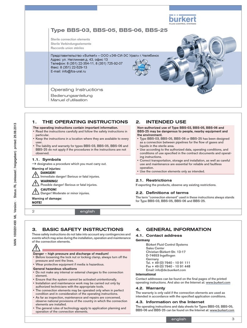
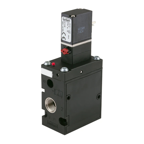
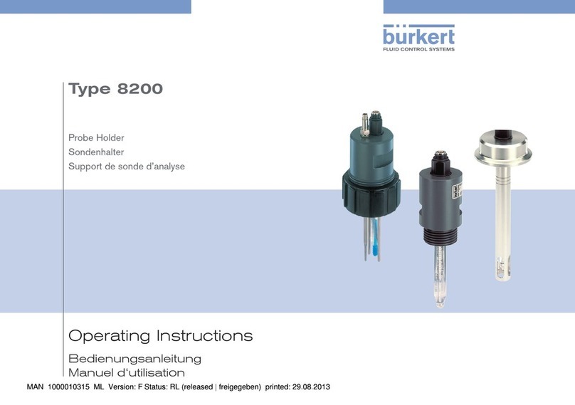
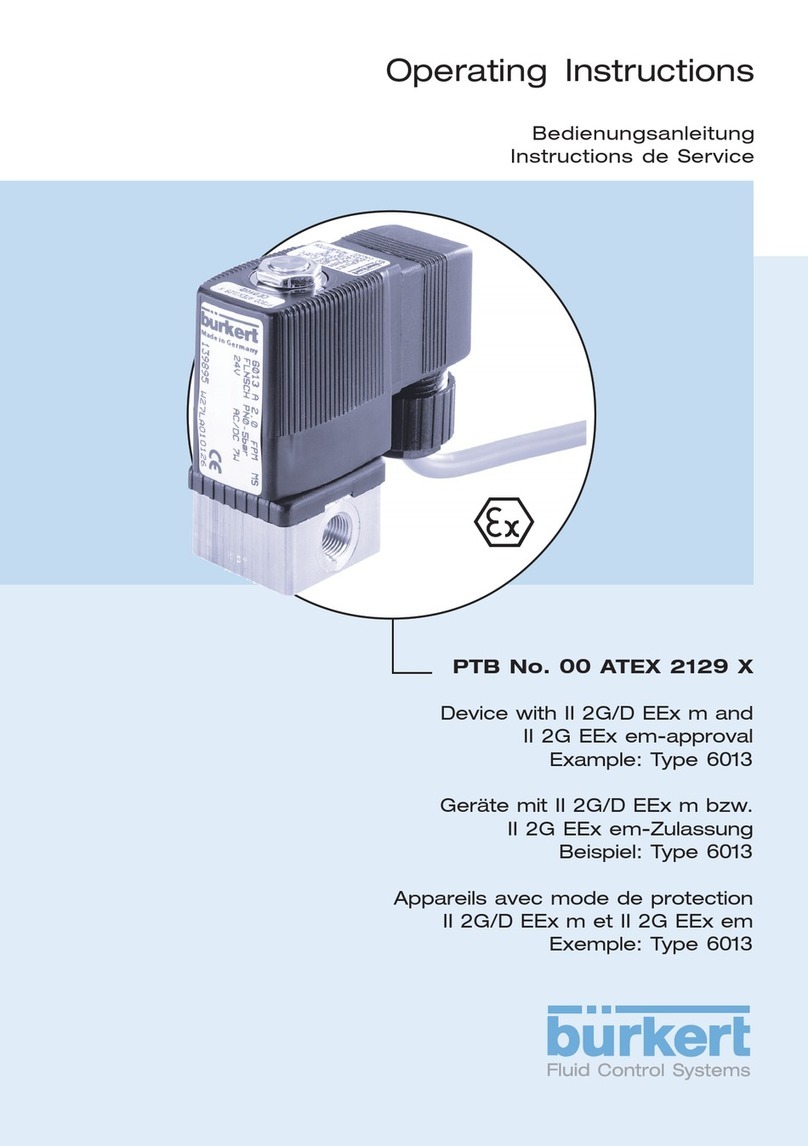
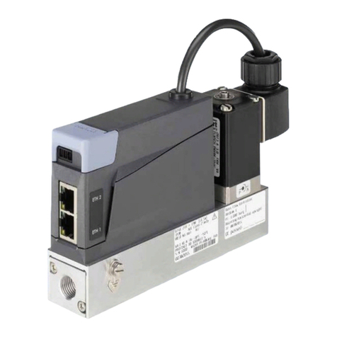
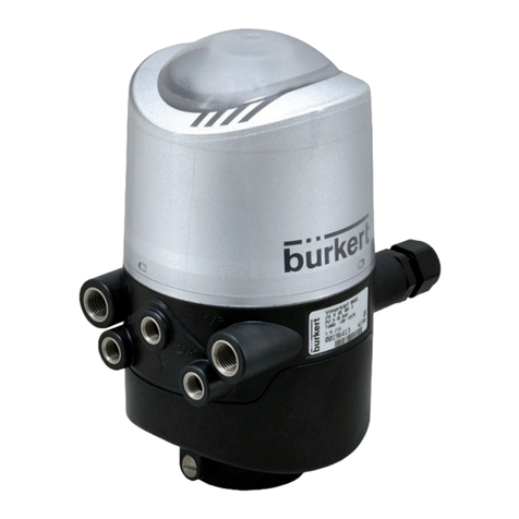
Burkert 8695 Series User manual

Operating Instructions
Type 8695 REV.3
Control Head

We reserve the right to make technical changes without notice.
Technische Änderungen vorbehalten.
Sous réserve de modifications techniques.
© Bürkert Werke GmbH & Co. KG, 2022
Operating Instructions 2209/00_EU-EN_00815434 / Original DE

3
Control head Type 8695 REV.3
Table of ConTenTs
1ABOUT THESE INSTRUCTIONS ............................................................................................................7
1.1 Symbols........................................................................................................................................7
1.2 Denitionofterms........................................................................................................................7
2INTENDED USE ......................................................................................................................................8
3BASIC SAFETY INSTRUCTIONS ...........................................................................................................9
4GENERAL INFORMATION....................................................................................................................10
4.1 Contact address.........................................................................................................................10
4.2 Warranty .....................................................................................................................................10
4.3 Trademarks.................................................................................................................................10
4.4 Informationontheinternet ........................................................................................................10
5SYSTEM DESCRIPTION.......................................................................................................................11
5.1 Structureandfunction ...............................................................................................................11
5.1.1 Control head for integrated installation on 21xx series (ELEMENT) ...........................11
5.1.2 Model for control of process valves belonging to the 20xx series (CLASSIC) ...........12
6TECHNICAL DATA ................................................................................................................................13
6.1 Standardsanddirectives...........................................................................................................13
6.2 Licenses .....................................................................................................................................13
6.3 Operatingconditions .................................................................................................................13
6.4 Mechanicaldata.........................................................................................................................14
6.5 Type labels .................................................................................................................................14
6.5.1 Type label standard ....................................................................................................14
6.5.2 UL type label...............................................................................................................14
6.5.3 UL additional label......................................................................................................15
6.6 Pneumaticdata ..........................................................................................................................15
6.7 Electricaldata ............................................................................................................................16
english
Type 8695 REV.3

4
Inhaltsverzeichnis
6.7.1 Electricaldatawithouteldbuscommunication........................................................16
6.7.2 Electrical data, IO-Link ...............................................................................................16
6.7.3 Electrical data, büS.....................................................................................................17
6.7.4 Electrical data, AS-Interface.......................................................................................17
6.8 Communication..........................................................................................................................18
6.8.1 IO-Link ........................................................................................................................18
7INSTALLATION......................................................................................................................................19
7.1 Safetyinstructions .....................................................................................................................19
7.2 InstallationofthecontrolheadType8695onprocessvalvesofseries21xx(ELEMENT) .....19
7.3 InstallationofthecontrolheadType8695onprocessvalvesofseries20xx(CLASSIC) ......24
7.4 Rotatingtheactuatormoduleonprocessvalvesofseries2100,2101,2000and2012 ........28
7.5 Rotatingthecontrolheadforprocessvalvesbelongingtoseries20xx .................................30
8PNEUMATIC INSTALLATION................................................................................................................31
9ELECTRICAL INSTALLATION...............................................................................................................33
9.1 Safetyinstructions .....................................................................................................................33
9.2 Electricalinstallation,withouteldbuscommunication...........................................................34
9.3 Electricalinstallation,IO-LinkportclassBandportclassA...................................................35
9.4 Electricalinstallation,büS .........................................................................................................35
9.5 Electricalinstallation,AS-Interface ...........................................................................................36
9.5.1 Connection with circular plug-in connector M12 x 1, 4-pin .......................................36
9.5.2 Connectionwithmulti-polecableandribboncableterminal.....................................37
10 START-UP ............................................................................................................................................. 38
10.1 Invertprocessvalvedirection ...................................................................................................38
10.2 Teachfunction:Determineendpositionsandsavethese,REV.3 ...........................................40
10.2.1 Automaticteachfunction............................................................................................40
10.2.2 Manual teach function ................................................................................................42
10.2.3 Teach-in-operation function........................................................................................44
10.3 SettingwithBürkertCommunicator..........................................................................................45
10.3.1 ConnectingIO-LinkdevicewithBürkertCommunicator............................................45
english
Type 8695 REV.3

5
10.4 IO-Link ........................................................................................................................................47
10.4.1 Information,IO-Link....................................................................................................47
10.5 Congurationoftheeldbus .....................................................................................................47
10.6 büS..............................................................................................................................................47
10.6.1 Information,büS .........................................................................................................47
10.6.2 Congurationoftheeldbus ......................................................................................47
10.7 AS-Interface ...............................................................................................................................48
10.7.1 Certication ................................................................................................................48
10.7.2 Programmingdata ......................................................................................................48
11 CONTROL AND DISPLAY ELEMENTS ................................................................................................49
11.1 Operatingstate............................................................................................................................. 50
11.2 Functionsoftheoperatinganddisplayelements ....................................................................51
11.3 Statusindicator..........................................................................................................................54
11.4 DescriptionoftheLEDmodes ..................................................................................................55
11.4.1 Valvemode .................................................................................................................55
11.4.2 Valvemodeanderror..................................................................................................55
11.4.3 Valvemodeandwarnings...........................................................................................56
11.4.4 NAMURmode.............................................................................................................57
11.4.5 Fixed colour ................................................................................................................57
11.4.6 LEDo........................................................................................................................ 57
11.5 Manualactuationoftheactuatorwithpilotvalve ....................................................................58
11.6 SettingtheLEDmode,statusindicator....................................................................................60
12 SAFETY END POSITIONS ....................................................................................................................61
13 MAINTENANCE ....................................................................................................................................61
14 DISASSEMBLY .....................................................................................................................................62
14.1 Safetyinstructions .....................................................................................................................62
14.2 Disassemblythecontrolhead...................................................................................................62
15 ACCESSORIES .....................................................................................................................................64
15.1 Communicationssoftware.........................................................................................................64
16 PACKAGING AND TRANSPORT .......................................................................................................... 65
english
Type 8695 REV.3
6
17 STORAGE .............................................................................................................................................65
18 DISPOSAL ............................................................................................................................................65
english
Type 8695 REV.3

7
About these instructions
1 ABOUT THESE INSTRUCTIONS
The operating instructions describe the entire life cycle of the device.
→Keep these instructions ready to hand at the operation site.
Importantsafetyinformation.
▶Carefully read these instructions.
▶Observe in particular the safety instructions, intended use and operating conditions.
▶Persons,whoworkonthedevice,mustreadandunderstandtheseinstructions.
1.1 Symbols
DANGER
Warnsofanimmediatedanger.
▶Failure to observe the warning will result in a fatal or serious injury.
WARNING
Warnsofapotentiallydangeroussituation.
▶Failuretoobservethewarningmayresultafatalorseriousinjury.
CAUTION
Warnsofapossibledanger.
▶Failuretoobservethewarningmayresultinmoderateorminorinjuries.
ATTENTION
Warnsofdamagetoproperty.
▶Failuretoobservethewarningmayresultindamagetodeviceorsystem.
Indicatesimportantadditionalinformation,tipsandrecommendations.
Referstoinformationintheseoperatinginstructionsorinotherdocumentation.
▶Indicates an instruction for risk prevention.
→Indicatesaprocedurewhichyoumustcarryout.
Indicates a result.
Menu Indicates a interface text.
1.2 Denition of terms
Intheseinstructionstheterm“device”denotesthefollowingdevicetypes:
Control head Type 8695 REV.3.
Theterm“büS”(Bürkertsystembus)usedinthisinstructionstandsforthecommunicationbusdeveloped
by Bürkert and based on the CANopen protocol.
Intheseinstructions,theabbreviation“Ex”alwaysrefersto“potentiallyexplosiveatmosphere”.
english
Type 8695 REV.3

8
Intended use
2 INTENDED USE
ThecontrolheadType8695REV.3isdesignedtobemountedonpneumaticactuatorsofprocess
valvesforthecontrolofmedia.Thepermitteduidmediaarelistedinthetechnicaldata.
▶Usethedeviceforitsintendedpurposeonly.Non-intendeduseofthedevicemaybedangeroustopeo-
ple,nearbyequipmentandtheenvironment.
▶Correcttransportation,correctstorageaswellascorrectinstallation,commissioning,operationand
maintenanceareessentialforreliableandproblem-freeoperation.
▶Whenusingthedevice,observethepermitteddata,operatingconditionsandapplicationconditions.
Thisinformationcanbefoundinthecontractualdocuments,theoperatinginstructionsandonthetype
label.
▶Usethedeviceonlyinconjunctionwiththird-partydevicesandcomponentsrecommendedandautho-
rized by Bürkert.
▶Donotusethedeviceoutdoorswithoutprotectionfromtheweather.
▶Inpotentiallyexplosiveatmosphere,onlyusedevicesapprovedforuseinthoseareas.Thesedevices
arelabeledwithaseparateExtypelabel.Forsuchuse,notetheinformationprovidedontheseparate
Extypelabelandtheadditionalexplosion-relatedinformationorseparateexplosion-relatedoperating
instructions.
english
Type 8695 REV.3

9
Basic safety instructions
3 BASIC SAFETY INSTRUCTIONS
These safety instructions do not consider any contingencies or incidents which occur during installation,
operationandmaintenance.
Theoperatorisresponsibleforobservingthelocation-specicsafetyregulations,alsowithreferencetothe
personnel.
DANGER
Riskofinjuryfromhighpressureanddischargeofmedium.
▶Beforeworkingonthedeviceorsystem,switchothepressure.Ventordrainlines.
DANGER
Riskofinjuryfromelectricshock.
▶Beforeworkingonthedeviceorsystem,switchothepowersupply.Secureagainstreactivation.
▶Observeapplicableaccidentpreventionandsafetyregulationsforelectricalequipment.
Topreventinjury,ensurethefollowing:
▶Securedeviceorsystemtopreventunintentionalactivation.
▶Onlytrainedtechniciansmayperforminstallationandmaintenancework.
▶Performinstallationandmaintenancewithsuitabletoolsonly.
▶Donotmakeanychangestothedeviceanddonotsubjectittomechanicalstress.
▶Operate the device only in perfect state and in consideration of the operating instructions.
▶Observe the general rules of technology.
▶Install the device according to the regulations applicable in the respective country.
▶Donotfeedcorrosiveorammablemediaintothedeviceconnections.
▶Donotfeedanyuidsintotheconnectionsofthedevice.
▶Aftertheprocessisinterrupted,restartinacontrolledmanner.Observesequence:
1.Connectelectricalorpneumaticpowersupply.
2.Chargethedevicewithmedium.
▶Observe intended use.
▶When unscrewing and screwing in the body casing or the transparent cap, do not hold the actuator of the
process valve but the basic housing of the device.
english
Type 8695 REV.3

10
General information
4 GENERAL INFORMATION
4.1 Contact address
Germany
BürkertFluidControlSystem
Chr.-Bürkert-Str. 13-17
D-74653Ingelngen
E-mail:[email protected]
International
Contactaddressescanbefoundonthenalpagesoftheprintedoperatinginstructions.
AndalsoontheInternetat:
www.burkert.com
4.2 Warranty
ThewarrantyisonlyvalidifthecontrolheadType8695isusedasintendedinaccordancewiththespecied
application conditions.
4.3 Trademarks
Brandsandtrademarkslistedbelowaretrademarksofthecorrespondingcompanies/associations/
organizations
Loctite HenkelLoctiteDeutschlandGmbH
4.4 Information on the internet
TheoperatinginstructionsanddatasheetsforType8695canbefoundontheInternetat:
www.burkert.com
english
Type 8695 REV.3

11
System description
5 SYSTEM DESCRIPTION
5.1 Structure and function
The control head Type 8695 can control single or double-acting process valves.
ThecontrolheadType8695hasbeenoptimizedfortheintegratedmodularttingofseries21xxprocessvalves
(ELEMENT) with actuator size ∅50.Variousexpansionstagesarepossiblethankstothemodulardesign.
Forinstallationonthe20xxseries(CLASSIC)thereisaspecialmodelwhichisdescribedinchapter“5.1.2”.
Thevalvepositionisrecordedviaacontactless,analogsensorelementwhichautomaticallydetectsandsaves
thevalveendpositionsbymeansoftheteachfunctionduringstart-up.
Variants:
•withouteldbuscommunication:24VdevicewithdigitalinputsandoutputsandbüSserviceinterface
•AS Interface
•IO-Link
•büS
5.1.1 Control head for integrated installation on 21xx series
(ELEMENT)
Electrical connection
Circular plug-in connector
M12 x 1 Air exhaust port
(label:3)
Pressurelimitingvalve
(for protection against too
high internal pressure in
case of error)
Pilot air port
(label:1)
Fastening screws (2 x)
Viewwithouttransparentcap:
Basic housing
Status indicator (RGB LED)
ASi PWR-LED (green)
ASi FAULT-LED (red)
Key 2
Key 1
büS service interface
Inv.ValveDir. LED
Manual LED
Pilot LED
Figure 1: Structure
english
Type 8695 REV.3

12
System description
5.1.2 Model for control of process valves belonging to the 20xx
series (CLASSIC)
AspecialmodelenablesthecontrolheadType8695tobeattachedtoprocessvalvesbelongingtothe
20xx series.
Thismodelhasadierentpneumaticconnectionmodulesothatthepilotairportscanbeconnectedtothe
outside of the actuator (see “Figure2”).
Pilot air outlet 22
Pilot air outlet 21
Figure 2: Model for control of process valves, 20xx series
english
Type 8695 REV.3

13
Technical data
6 TECHNICAL DATA
6.1 Standards and directives
ThedevicecomplieswiththerelevantEUharmonisationlegislation.Inaddition,thedevicealsocomplies
withtherequirementsofthelawsoftheUnitedKingdom.
Theharmonisedstandardsthathavebeenappliedfortheconformityassessmentprocedurearelistedinthe
currentversionoftheEUDeclarationofConformity/UKDeclarationofConformity.
6.2 Licenses
Theproductisapprovedforuseinzone2and22inaccordancewithATEXdirective2014/34/EUcategory
3GD.
Observeinstructionsonoperationinapotentiallyexplosiveatmosphere(Exarea).
ObservetheATEXadditionalinstructions.
The product is cULus approved. Instructions for use in the UL area see chapter “6.7Electricaldata”.
6.3 Operating conditions
WARNING!
Solarradiationandtemperatureuctuationsmaycausemalfunctionsorleaks.
▶If the device is used outdoors, do not expose it unprotected to the weather conditions.
▶Ensurethatthepermittedambienttemperaturedoesnotexceedthemaximumvalueordropbelowthe
minimumvalue.
Ambienttemperature seetypelabel
Degree of protection
Evaluatedbythemanufacturer: EvaluatedbyUL:
IP65/IP67accordingtoEN605291) UL Type 4x Rating, indoor only 1)
Operatingaltitude upto2000mabovesealevel
Relativeairhumidity max.90%at55°C/60°C(noncondensing)
1) Only if cables, plugs and sockets have been connected correctly and in compliance with the exhaust air concept see
chapter “8 Pneumatic installation”.
english
Type 8695 REV.3

14
Technical data
6.4 Mechanical data
Dimensions Seedatasheet
Bodymaterial exterior PPS,PC,VA
interior PA6; ABS
Sealingmaterial exterior EPDM/FKM
Stroke range of valve spindle
21xx series (ELEMENT)
and20xxseries(CLASSIC) 2–35mm
Third-party devices
(modiedguideelementrequired) 2–44mm
6.5 Type labels
6.5.1 Type label standard
869524V/DC
single act Pilot 0,6
Pmax7bar
Tamb0°C-+55°CREV.2
S/N001000
00185114
D-74653 Ingelfingen
W14UN
Ordernumber
Supplyvoltageoreldbauscontrol
Max. operating pressure
Type Control function, pilot valve
Barcode
Serialnumber,CEmarking
Ambienttemperature,version
Figure 3: Type label (example)
6.5.2 UL type label
8695 -E1-...-0 PU02
Single act Pilot 0.6 24V
Pmax7bar
Tamb-10-+55°CREV.2
S/N1001
00123456
D-74653 Ingelfingen
W15MA
Ordernumber,manufacturecode
Max. operating pressure
Type, Features of the type code applicable to UL and ATEX
Control function, pilot valve,
supply voltage pilot valve
Barcode
Serialnumber,CEmarking
Ambienttemperature,version
Figure 4: UL type label (example)
english
Type 8695 REV.3

15
Technical data
6.5.3 UL additional label
E238179
Degree of protection
Circuitwithlimitedpower
Communication,
supply voltage
Type 4X enclosure
NEC Class 2 only
PowerSupply:büS
24V±25%
max.3,5W
Powerconsumption
Figure 5: UL additional label (example)
6.6 Pneumatic data
Controlmedium neutralgases,air
Quality classes in accordance with ISO 8573-1
Dustcontent Class7 max.particlesize40µm,max.particledensity10mg/m³
Watercontent Class3 max.pressuredewpoint
-20°Cormin.10°Cbelowthelowestoperatingtemperature
Oilcontent ClassX max.25mg/m³
Temperaturerange -10–+50°C
Pressure range 3 – 7 bar
Air output of pilot valve 7 lN/min(foraerationanddeaeration)
(QNn-valueaccordingtodenitionforpressuredropfrom7to6bar
absolute)
Connections 21xx (ELEMENT) Plug-in hose connector ∅6mm(1/4“)
SocketconnectionG1/8
20xx(CLASSIC) SocketconnectionG1/8
with M5 connection for connecting to the actuator
english
Type 8695 REV.3

16
Technical data
6.7 Electrical data
WARNING!
OnlycircuitswithlimitedpowermaybeusedforULapprovedcomponentsaccordingto“NECClass2”.
6.7.1 Electrical data without eld bus communication
Protection class III as per DIN EN 61140 (VDE 0140-1)
Connection
Supply Circular plug-in connector (M12 x 1, 8-pin)
Communication büSserviceinterface
Operating voltage 24 V ±25%,max.residualripple10%
Currentconsumption 90mA@18V+currentloadforanactivedigitaloutput
Digital output 2 x 24V PNP
Outputcurrent max.100mAperoutput
Outputvoltage Low=GND+max.2VandHigh=operatingvoltage–max.2V
Digital input 24 V potential-free (suitable for PNP and NPN control)
Outputcurrent max.9mA@30V (as per EN 61131-2 Type 1)
Output voltage Low = 0...5 V and High = 15...30 V
(as per EN 61131-2 Type 1)
Powerconsumptionincl.loadon
oneactivedigitaloutput 2W/5W
Communicationsoftware BürkertCommunicator
6.7.2 Electrical data, IO-Link
Protectionclass IIIasperDINEN61140(VDE0140-1)
Connection
Supply, IO-Link Circular plug-in connector M12 x 1, 5-pin, port class A
Circular plug-in connector M12 x 1, 5-pin, port class B
Communication büSserviceinterface
Operating voltage
Systemsupply(Pin1+3) 24V ±25%(accordingtospecication)
OnlyforportclassB:
Actuatorsupply(Pin2+5)2) 24 V ±25%(accordingtospecication)
Currentconsumption
Systemsupply(Pin1+3) PortclassA:max.150mA,onlywithinstalledpilotvalves
PortclassB:max.100mA
OnlyforportclassB:
Actuatorsupply(Pin2+5) max.50mA
Totalpowerconsumption max.3.5W
2) Actuator supply is galvanically isolated from system supply in accordance with IEC 60664 and for electrical safety in
accordance with SELV from IEC 61010-2-201
english
Type 8695 REV.3

17
Technical data
6.7.3 Electrical data, büS
Protectionclass IIIasperDINEN61140(VDE0140-1)
Connection Circular plug-in connector M12 x 1, 5-pin, A coded
Operating voltage 24 V ±25%
Currentconsumption max.150mA,onlywithinstalledpilotvalve
Totalpowerconsumption max.3.5W
6.7.4 Electrical data, AS-Interface
Protection class III as per DIN EN 61140 (VDE 0140-1)
Connection
Supply, AS-Interface Circular plug-in connector M12 x 1, 4-pin
Communication büSserviceinterface
Operating voltage
SystemsupplyAS-Interface
(Pin1+3) viaAS-Interfacepowersupplyunitaccordingtospecicationwith
29.5 V...31.6 V
Powerconsumption
Output pilot valve approx. 0.8 W incl. integrated watchdog function
Currentconsumption max.110mA,onlywithinstalledpilotvalve
Communicationsoftware BürkertCommunicator
english
Type 8695 REV.3

18
Technical data
6.8 Communication
6.8.1 IO-Link
Port class A B
IO-LinkSpecication V1.1.2
Supply via IO-Link (M12 x 1, 5-pin, A-coded)
SIOmode No
IODDle see Internet
VendorID 0x0078, 120
DeviceID seeIODDle
ProductID 8695 Class A 8695 Class B
Transmissionspeed COM3(230,4kbit/s)
PD Input Bits 56
PD Output Bits 8
M-sequence Cap. 0x0D
Min.cycletime 5ms
Data Storage Yes
Max. cable length 20m
english
Type 8695 REV.3

19
Installation
7 INSTALLATION
7.1 Safety instructions
DANGER!
Riskofinjuryfromhighpressureintheequipment/device.
▶Beforeworkingonequipmentordevice,switchothepressureanddeaerate/drainlines.
Riskofelectricshock.
▶Beforeworkingonequipmentordevice,switchothepowersupplyandsecuretopreventreactivation.
▶Observeapplicableaccidentpreventionandsafetyregulationsforelectricalequipment.
WARNING!
Riskofinjuryfromimproperinstallation.
▶Installationmaybecarriedoutbyauthorizedtechniciansonlyandwiththeappropriatetools.
Riskofinjuryfromunintentionalactivationofthesystemandanuncontrolledrestart.
▶Securesystemfromunintentionalactivation.
▶Followingassembly,ensureacontrolledrestart.
7.2 Installation of the control head Type 8695 on process
valves of series 21xx (ELEMENT)
ATTENTION!
Whenmountingonprocessvalveswithaweldedconnection,followtheinstallationinstructionsinthe
operatinginstructionsfortheprocessvalve.
Procedure:
1. Install switch spindle
Transparent cap
Actuator
Pilot air ports
(plug-in hose connectors with collets
or threaded bushings)
Figure 6: Installation of switch spindle (1), series 21xx
→Unscrew the transparent cap on the actuator and unscrew the position display (yellow cap) on the
spindle extension (if present).
english
Type 8695 REV.3

20
Installation
→Forversionwithplug-inhoseconnector,removethecollets(whitenozzles)frombothpilotairports(if
present).
Spindle extension
O-ring
Guideelement
Actuator cover
Groove ring
Puck
Switch spindle
max.5Nm
max.1Nm
Figure 7: Installation of the switch spindle (2), series 21xx
ATTENTION!
Improperinstallationmaydamagethegrooveringintheguideelement.
Thegrooveringisalreadybepre-assembledintheguideelementandmustbe“lockedintoposition”
intheundercut.
▶Wheninstallingtheswitchspindle,donotdamagethegroovering.
→Pushtheswitchspindlethroughtheguideelement.
ATTENTION!
Screwlockingpaintmaycontaminatethegroovering.
▶Do not apply any screw locking paint to the switch spindle.
→Tosecuretheswitchspindle,applysomescrewlockingpaint(Loctite290)inthetappedboreofthespindle
extension in the actuator.
→Check that the O-ring is correctly positioned.
→Screwtheguideelementtotheactuatorcover(maximumtorque:5Nm).
→Screw switch spindle onto the spindle extension. To do this, there is a slot on the upper side
(maximumtorque:1Nm).
→Push puck onto the switch spindle and lock into position.
english
Type 8695 REV.3
Other manuals for 8695 Series
1
Table of contents
Other Burkert Industrial Equipment manuals

Burkert
Burkert buS User manual

Burkert
Burkert 8200 Series User manual

Burkert
Burkert AC10 5-PD47 Series User manual

Burkert
Burkert PTB 14 ATEX 2023 X User manual

Burkert
Burkert 6104 User manual

Burkert
Burkert 6519 User manual

Burkert
Burkert 8644 AirLINE User manual

Burkert
Burkert 8741 User manual

Burkert
Burkert MP05 User manual

Burkert
Burkert 6105 User manual
Popular Industrial Equipment manuals by other brands

Mitsubishi Electric
Mitsubishi Electric BC34 Installation, operation & maintenance manual

allfi
allfi 921300 Assembly, Operating and Maintenance Instruction

Enerpac
Enerpac SGH Series instruction sheet

Asutec
Asutec ASM-150 operating manual

Strobel
Strobel VEB100-3 operating instructions

ABB
ABB OHDI-01 user manual