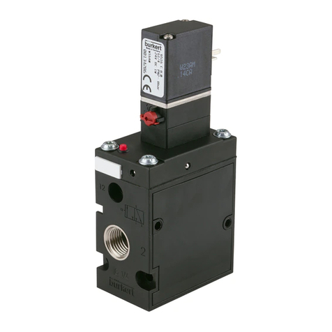
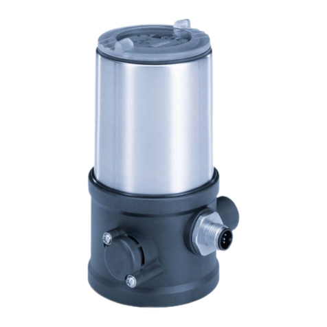
Burkert 6519 User manual

Fluid Control Systems
Mehrfachblöcke / Block Assemblies / Blocs multiples
Type 6518,Type 6519
Modulare pneumatische Grundschiene /
Modular Pneumatic Basic Rail /
Profil pneumatique modulaire
Type MP07
Betriebsanleitung / Operating Instructions / Instructions de service

Typ 6518/6519 u. Typ MP07
Sie
•haben technische Fragen oder Probleme
•wollen mehr wissen über die Produkte und Produktpalette der Fa. Bürkert
•haben Anregungen zu dieser Betriebsanleitung
Wir
•sind unter den auf der Rückseite genannten Adressen und Telefonnummern für Sie zu
erreichen
You
•have technical questions or problems
•want to know more about these products and about the Bürkert product range
•have comments regarding these operating instructions
We
•are available to help you at the addresses and telephone numbers listed at the
backside of the cover
Vous
•avez des questions techniques ou des problèmes
•voulez en savoir davantage sur les produits et la gamme des produits de la maison
Bürkert
•avez des suggestions concernant ces instructions de service
Nous
•sommes à votre disposition aux adresses et numéros de téléphone de la couverture

Betriebsanleitung-Nr. 803 150
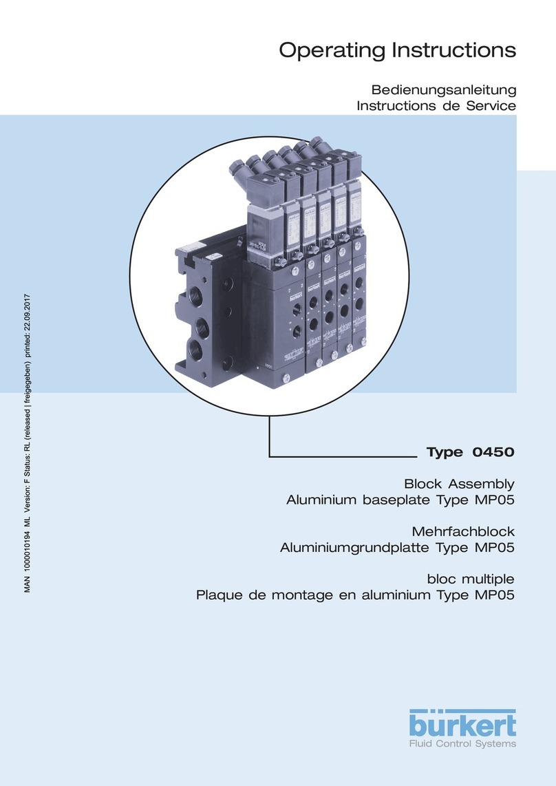
Bild 1: Beispiel eines Mehrfachblocks
Figure 1: Example of a block assembly
Figure 1: Exemple d'un bloc multiple

deutsch
Betriebsanleitung-Nr. 803 150 1
Mehrfachblöcke
Typ 6518,Typ 6519
und
modulare pneumatische Grundschiene
Typ MP07
Inhalt:
1 ALLGEMEINE SICHERHEITSHINWEISE 2
2 DARSTELLUNGSMITTEL 2
3 ALLGEMEINE BESCHREIBUNG 3
3.1 Ventilaufbau 3
3.2 Wirkungsweisen der VentileTyp 6518 / 6519 3
3.3 Medien 4
3.4 Elektrischer Anschluß 4
4 MONTAGE, INBETRIEBNAHME UND WARTUNG 5
4.1 Aufbau von Mehrfachblöcken mit der modularen pneumatischen
Grundschiene MP07 5
4.2 Demontage der Module 6
4.3 Weitere Einsatzmöglichkeiten der Anschlußmodule - rechts - 6
4.4 Befestigung des Ventilblocks 6
4.4.1 Normschiene 6
4.4.2 Wandmontage 7
4.5 Befestigung von Einzelventilen 7
4.5.1 Steckanschlüsse 7
4.5.2 Demontage der Steckanschlüsse 8
4.6 Maßnahmen vor der Inbetriebnahme 8
4.7 Impulsbetrieb 8
4.8 Störungen 9
5 NOTIZEN 10

deutsch
Typ 6518/6519 u. Typ MP07
2
Zulassungen wie Ex, UL, UR, CSA, DVGW usw. werden auf
dem Typenschild oder durch einen besonderen Aufkleber
gekennzeichnet
HINWEIS
1 ALLGEMEINE SICHERHEITSHINWEISE
Beachten Sie die Hinweise dieser Betriebsanleitung sowie die Einsatz-
bedingungen und zulässigen Daten gemäß Datenblatt Typ 6518 bzw. 6519, damit
das Gerät einwandfrei funktioniert und lange einsatzfähig bleibt:
•halten Sie sich bei der Einsatzplanung und dem Betrieb des Gerätes an die allgemei-
nen Regeln der Technik;
•beachten Sie, daß in Systemen, die unter Druck stehen, Leitungen und Ventile nicht
gelöst werden dürfen;
•beachten Sie die geltenden Unfallverhütungs- und Sicherheitsbestimmungen für
elektrische Geräte während des Betriebs, der Wartung und der Reparatur des Gerätes;
schalten Sie vor Eingriffen in das Systwem in jedem Fall die Spannung ab;
•treffen Sie geeignete Maßnahmen, um unbeabsichtigtes Betätigen oder unzulässige
Beeinträchtigung auszuschließen;
•bei Nichtbeachtung dieser Hinweise entfällt jegliche Haftung unsererseits, ebenso
erlischt die Garantie auf Geräte u. Zubehörteile.
2 DARSTELLUNGSMITTEL
In dieser Betriebsanleitung werden folgende Darstellungsmittel verwendet:
markiert einen Arbeitsschritt, den Sie ausführen müssen
ACHTUNG! kennzeichnet Hinweise, bei deren Nichtbeachtung Ihre Ge-
sundheit oder die Funktionsfähigkeit des Gerätes gefährdet ist
HINWEIS kennzeichnet wichtige Zusatzinformationen, Tips und
Empfehlungen

deutsch
Betriebsanleitung-Nr. 803 150 3
Steckanschlüsse gelten nur für die Arbeitsanschlüsse
2 (B) und 4 (A).
Die Ventile arbeiten wartungsfrei.
Der Vakuumerzeuger muß an Anschluß 1 angeschlossen
werden!
ACHTUNG!
3.2 Wirkungsweisen der Ventile Typ 6518 / 6519
3/2-Wege-Ventil:
in Ruhestellung Druckanschluß 1 gesperrt, Ausgang 2 entlüftet
3/2-Wege-Ventil für Vakuum, mit Steuerhilfsluft:
in Ruhestellung Druckanschluß 1 gesperrt, Ausgang 2 entlüftet
3/2-Wege-Ventil:
in Ruhestellung Druckanschluß 1 mit Ausgang 2 verbunden
5/2-Wege-Ventil:
in Ruhestellung Druckanschluß 1 mit Ausgang 2 verbunden,
Ausgang 4 entlüftet
HINWEIS
3 ALLGEMEINE BESCHREIBUNG
3.1 Ventilaufbau
• 3/2-Wege-Vorsteuerventil mit unterschiedlichen elektrischen Anschlußvarianten
• die übergesteckte Spule ist in 4 x 90°-Schritten arretierbar, dazwischen um das
Kernführungsrohr beliebig positionierbar
• Ventilgehäuse mit Membran und Sitzdichtungen (3/2 und 5/2) bzw. Schieber (5/3)
• Arbeitsanschlüsse 2 (B) / 4 (A) sowie Versorgungs- und Entlüftungsanschlüsse
1 (P) / 3 (S) / 5 (R) mit G1/4-Innengewinde oder Steckanschluß für Schlauchdurch-
messer 8 mm
• die Ventile können auf den modularen pneumatischen Grundschienen Typ MP07 zu
Ventilblöcken montiert werden
• beliebige Einbaulage, vorzugsweise mit Magnetsystem oben
die Ventile sind auch in explosionsgeschützter Ausführung verfügbar

deutsch
Typ 6518/6519 u. Typ MP07
4
5/3-Wege-Ventil:
in Mittelstellung alle Anschlüsse gesperrt
5/3-Wege-Ventil:
in Mittelstellung Ausgänge 2 und 4 entlüftet,
Druckanschluß 1 gesperrt
ACHTUNG!
HINWEIS Der Steuerdruck bei pneumatischer Ansteuerung ist abhängig
vom Druck des Durchflußmediums; er darf maximal 8 bar
betragen!
3.3 Medien
• gefilterte Druckluft (Partikelgröße max. 10 µm), vorzugsweise ungeölt, Betrieb mit
geölter Luft ist möglich; neutrale Gase
• Dichtwerkstoffe: NBR oder PUR für 3/2- und 5/2-Ventile
NBR für 5/2-Impuls- und 5/3-Ventile
• zulässige Temperatur: Medium: -10 bis +50° C
Umgebung: -10 bis +55° C
• Betriebsdruckbereich: 2 - 8 bar
Achten Sie beim Verschrauben der Gerätesteckdose mit der
Spule auf einwandfreien Sitz der Flachdichtung!
ACHTUNG!
3.4 Elektrischer Anschluß
• entnehmen Sie Spannung, elektrische Leistung und Stromart dem Typenschild!
• Spannungstoleranz ±10 %
• elektrischer Anschluß: Gerätesteckdose Typ 2508 an den Anschlußsteckerfahnen der
Spule (Drehmoment zur Befestigung: 1 Nm)
• Schutzart IP65 (nur in Verbindung mit der Gerätesteckdose Typ 2508)
• die Gerätesteckdose ist zur Wahl der Kabelganges um 4 x 90° versetzt montierbar
• weitere elektrische Anschlußmöglichkeiten siehe Typ 6014 bzw. 8640
Beachten Sie den zulässigen Druckbereich auf dem Typen-
schild!
Druckdifferenz zwischen Anschluß 1 und 3/5 ≥≥
≥≥
≥ 2 bar

deutsch
Betriebsanleitung-Nr. 803 150 5
ACHTUNG! In Systemen, die unter Druck stehen, dürfen Leitungen oder
Ventile nicht gelöst werden!
Beachten Sie die Druckanzeige am rechten Anschlußmodul!
4 MONTAGE, INBETRIEBNAHME UND WARTUNG
Eingriffe dürfen nur durch Fachpersonal und mit geeignetem Werkzeug erfolgen!
Schalten Sie vor Eingriffen in das System in jedem Fall die Spannung ab!
Säubern Sie vor Montage des Ventils die Rohrleitungen!
Schalten Sie gegebenenfalls zum Schutz vor Störungen einen Schmutzfänger vor.
Verwenden Sie die Spule in keinem Fall als Hebel, wenn Sie die Anschlüsse
einschrauben!
Achten Sie auf Übereinstimmung der Betriebsbedingungen mit den Leistungsdaten des
Gerätes!
Vermeiden Sie Staudrücke in den Abluftkanälen durch großvolumige Schalldämpfer!
•Druckanzeige mit Anzeigestift am Anschlußmodul - rechts - (Bild 1)
- Anzeigestift läßt sich eindrücken: Druck im Ventilblock < 1 bar
- Anzeigestift läßt sich nicht eindrücken: Ventilblock ist druckbeaufschlagt
- Anzeigestift federt zurück: Ventilblock ist druckbeaufschlagt
(entlüften Sie das System, bevor Sie
Leitungen oder Geräte demontieren)
4.1 Aufbau von Mehrfachblöcken mit der modularen
pneumatischen Grundschiene MP07
Sie erhalten durch die Kombination von 2fach- und 3fach- Grundmodulen beliebig große
Ventilblöcke.
Beginnen Sie den Aufbau zweckmäßig mit dem
Anschlußmodul - links - (Bild 1).
HINWEIS
ACHTUNG! Gequetschte O-Ringe und Profildichtungen haben Undichtheit
des Blocks zur Folge!
Kontrollieren Sie die Module auf vollständige Bestückung mit O-Ringen!
Ölen oder fetten Sie die aufgezogenen O-Ringe vor dem Rasten leicht ein.
Rasten Sie die Haken des anzubauenden Moduls in die Rastnuten des vorgehenden
Moduls ein, achten Sie dabei auf exakten Sitz der O-Ringe.
Drücken Sie die Module bis zum Einrasten beider Haken zusammen.
Achten Sie auf exakten Sitz der Profildichtungen auf dem Grundmodul!
deutsch
6Typ 6518/6519 u. Typ MP07
Befestigen Sie die Ventile mit je 2 M4-Schrauben auf dem Grundmodul
(Anzugsmoment max. 1,5 Nm).
Montieren Sie den kompletten Ventilblock auf der Wand oder auf der Normschiene.
Schließen Sie Versorgungs- und Arbeitsleitungen an.
Stellen Sie die elektrischen Anschlüsse zu den Vorsteuerventilen her; beachten Sie
dabei die Werte auf dem Typenschild!
4.2 Demontage der Module
Rasten Sie beide Rasthaken mittels Schraubendreher an den stirnseitigen Demontage-
nuten aus.
Nehmen Sie den Teilblock / das Modul seitlich ab.
4.3
Weitere Einsatzmöglichkeiten der Anschlußmodule
- rechts -
•als Teilermodule bei besonderen Anwendungsfällen zum Aufbau von mehreren
Betriebs-Druckstufen in einem Block;
•zusätzliche Einspeisung bei größeren Ventilblöcken.
Durchstoßen Sie bei Bedarf die seitlichen Sollbruchstellen der
Anschlüsse 1, 3 und 5 und die der oberen Vorsteuerentlüftung.
HINWEIS
4.4 Befestigung des Ventilblocks
4.4.1 Normschiene
•Normschiene 35 x 15 DIN 50022 (Standard)
•Normschiene 75 x 25 DIN 50023
HINWEIS Setzen Sie bei Verwendung der Normschiene 75 x 25 DIN 50023
die vormontierten Schrauben mit Klemmstücken und Federn ent-
sprechend um.
Montage
Hängen Sie den Ventilblock mit der oberen Nut in die Normschiene ein.
Rasten Sie die unteren Klemmstücke in die Normschiene ein.
Ziehen Sie die Schrauben an den Klemmstücken fest.
Demontage
Lösen Sie die Klemmschrauben (ca. 4 Umdrehungen).
Entnehmen Sie den Block nach oben von der Normschiene.

deutsch
Betriebsanleitung-Nr. 803 150 7
4.4.2 Wandmontage
Befestigen Sie den Ventilblock mit M5-Schrauben direkt an der Wand.
4.5.1 Steckanschlüsse
HINWEIS
ACHTUNG! Verspannen Sie das Ventilgehäuse beim Einbau nicht!
4.5 Befestigung von Einzelventilen (Bild 3)
Befestigen Sie das Einzelventil mit M4-Schrauben direkt an der Wand.
Für die Steckanschlüsse müssen die Schlauchleitungen folgende
Anforderungen erfüllen:
•Mindesthärte von 40 Shore D (nach DIN 53505 bzw. ISO 868);
•Außendurchmesser entsprechend DIN 73378 (max. zul.
Abweichung ± 0,1 mm vom Nennmaß);
•gratfrei, rechtwinklig abgeschnitten und am Außendurchmesser
unbeschädigt;
•die Schlauchleitungen sind bis zum Anschlag in die Steckan-
schlüsse einzudrücken.
Bild 2: Befestigung des Ventilblocks

deutsch
8Typ 6518/6519 u. Typ MP07
4.5.2 Demontage der Steckanschlüsse
Drücken Sie zum Lösen der Leitungen den Druckring ein und ziehen Sie die Schlauch-
leitung heraus.
ACHTUNG! Beachten Sie die Angabe “Impuls” auf dem Typenschild!
Vermeiden Sie gleichzeitige Impulsgabe auf beide Spulen!
HINWEIS Mit der Handbetätigung sind die Ventile umsteuerbar.
M4-Schrauben
zur Wandmontage
des Einzelventils
Handbetätigung
Drücken Sie zur manuellen Betätigung des
Ventils die Handbetätigung bis zum Anschlag
ein. Durch anschließendes Drehen um 90° nach
rechts ist die Handbetätigung verriegelt.
Anzeigestift zur pneumatischen Stellungsan-
zeige.
Bei ungeschaltetem Ventil läßt sich der rote
Anzeigestift eindrücken. Wird das Ventil geschal-
tet, fährt der Anzeigestift aus und bleibt in dieser
Stellung. Bei jeder Funktionsüberprüfung muß
der Anzeigestift erneut eingedrückt werden.
Kennzeichnungsschild (abnehmbar für Markie-
rungen/Beschriftungen)
Anschluß 14
• in Standardausführung nicht belegt
• dient als Steuerhilfsluftanschluß und als
Anschluß für pneumatische Ansteuerungen
Arbeitsanschlüsse
2 (B) und 4 (A)
Vorsteuerventil
4.6 Maßnahmen vor der Inbetriebnahme
Überprüfen Sie Anschlüsse, Spannung und Betriebsdruck!
Beachten Sie, daß max. Betriebsdaten (siehe Typenschild) nicht überschritten werden!
Überprüfen Sie die vorschriftsmäßige Belegung der Anschlüsse 1 und 3 bzw. 5, diese
dürfen auf keinen Fall vertauscht werden!
Entriegeln Sie bei elektrischem Betrieb die Handbetätigung!
4.7 Impulsbetrieb
Funktion: Die impulsgesteuerten Magnetventile arbeiten mit zwei Spulen, die im
Wechsel geschaltet werden.
Bild 3: Befestigung des Einzelventils / Handbetätigung / Pneumatische Stellungsanzeige

deutsch
Betriebsanleitung-Nr. 803 150 9
Behebung
Überprüfen Sie den elektri-
schen Anschluß.
Stellen Sie die Betriebsspan-
nung laut Typenschild sicher.
Bringen Sie die Handbetätigung
in Null-Stellung.
Führen Sie die Druck-
versorgung möglichst großvolu-
mig aus (auch bei vorgeschalte-
ten Geräten wie Druckreglern,
Wartungseinheiten, Absperr-
ventilen usw.).
Mindestbetriebsdruck ≥≥
≥≥
≥2 bar
Führen Sie die Druck-
versorgung möglichst großvolu-
mig aus (auch bei vorgeschalte-
ten Geräten wie Druckreglern,
Wartungseinheiten, Absperr-
ventilen usw.).
Mindestbetriebsdruck ≥≥
≥≥
≥2 bar
Verwenden Sie entsprechend
groß dimensionierte Geräusch-
dämpfer bzw. Expansions-
gefäße.
Reinigen Sie verschmutzte
Geräuschdämpfer.
Beaufschlagen Sie die Abluft-
kanäle mit impulsartigem
Druck, um die Verunreinigungen
auszublasen; bauen Sie ein
neues Vorsteuer- bzw. Haupt-
ventil ein, wenn diese Maßnah-
me keinen Erfolg bringt.
Ermitteln Sie die Leckstelle
oder fehlende Dichtungen.
Setzen Sie fehlende Dichtungen
ein oder erneuern Sie beschä-
digte Dichtungen.
4.8 Störungen
mögliche Ursache
keine oder nicht ausreichen-
de Betriebsspannung;
Handbetätigung nicht in
neutraler Stellung;
Druckversorgung nicht aus-
reichend oder nicht vorhan-
den.
Druckversorgung nicht aus-
reichend oder nicht vorhan-
den;
keine ausreichende Entlüf-
tung der Abluftkanäle durch
zu kleine oder verschmutzte
Geräuschdämpfer (Rück-
drücke);
Verunreinigungen bzw.
Fremdkörper im Vorsteuer-
oder Hauptventil.
fehlende oder gequetschte
O-Ringe zwischen den Mo-
dulen;
fehlende oder falsch positio-
nierte Profildichtungen zwi-
schen Ventil und Grund-
platte.
Störung
Ventile schalten nicht:
Ventile schalten verzö-
gert oder blasen an
den Entlüftungsan-
schlüssen ab:
undichte Ventilblöcke:

deutsch
10 Typ 6518/6519 u. Typ MP07
5 NOTIZEN

english
Operating Instructions-No. 803 150 11
Block Assemblies
Type 6518, 6519
and
Modular Pneumatic Basic Rail
Type MP07
Contents:
1 GENERAL SAFETY INSTRUCTIONS 12
2 SYMBOLS USED 12
3 GENERAL DESCRIPTION 13
3.1 Valve Construction 13
3.2 Valve operations of the Type 6518 / 6519 13
3.3 Media 14
3.4 Electrical connections 14
4 INSTALLATION, INITIALISATION AND SERVICE 15
4.1 Setting up block assemblies using the modular pneumatic rail
type MP07 15
4.2 Dismantling the module 16
4.3 Other possible uses of the connecting module, - right-hand - 16
4.4 Mounting the valve block 16
4.4.1 Standard rails 16
4.4.2 Wall mounting 17
4.5 Mounting single valves 17
4.5.1 Plug-in connections 17
4.5.2 Dismantling the plug-in connections 18
4.6 Measures to be taken before putting into service 18
4.7 Pulse operation 18
4.8 Faults 19
5 NOTES 20

12 Type 6518/6519 and type MP07
english
1 GENERAL SAFETY INSTRUCTIONS
To ensure that the device will function correctly, and have a long service life,
please comply with the information in these Operating Instructions, as well as with
the application conditions and additional data given in the Type 6518 and 6519
data sheet:
•When planning the application of the device, and during its operation, observe the
general technical rules!
•Observe the relevant accident prevention and safety regulations applicable for
electrical equipment throughout the operation, maintenance and repair of the device;
always switch off the voltage supply before working on the system!
•Note that lines and valves must not be unscrewed from systems that are under
pressure!
•Take suitable measures to prevent unintentional operation or impermissible
impairment!
•If these instructions are ignored, no liability will be accepted from our side, and the
guarantee on the device and on accessories will become invalid!
Approvals such as Ex, UL, UR, CSA, DVGW etc., will be
indicated on the rating plate, or by a special label.
NOTE
2 SYMBOLS USED
In these Operating Instructions, the following symbols are used:
indicates a working step that you will have to carry out
ATTENTION! indicates information which must be followed. Failure to do this
could endanger your health or the functionality of the device
indicates important additional information, tips and
recommendations
NOTE

english
Operating Instructions-No. 803 150 13
3 GENERAL DESCRIPTION
3.1 Valve Construction
• 3/2 way pilot valve with various electrical connection possibilities
• the top-mounted coil can be locked in 4 x 90° steps, for optional positioning in between
around the core guide tube
• valve body with diaphragm and seat seals (3/2 and 5/2), or with gate valve (5/3)
• working connections 2 (B) / 4 (A) and supply and ventilation connections 1 (P) / 3 (S) /
5 (R) with G 1/4 internal thread or plug connection for 8 mm hose external diameter
• the valves can be mounted on the modular pneumatic basic rail Type MP07
• can be mounted in any position, preferably with the magnetic system at the top
the valves are also available in explosion-proof versions
3.2 Valve operations of theType 6518 / 6519
3/2 way valve:
In de-energised position, Pressure Inlet 1 closed,
Outlet Port 2 exhausted
3/2 way valve for vacuum, with auxiliary pilot air:
In de-energised position, Pressure Inlet 1 closed,
Outlet Port 2 exhausted
The vacuum generator must be connected to port 1!
3/2 way valve:
In de-energised position, Pressure Inlet 1 connected
to Outlet Port 2
5/2 way valve:
In de-energised position, Pressure Inlet 1 connected
to Outlet Port 2, Outlet Port 4 exhausted.
ATTENTION!
NOTE Plug-in connections only for the service ports 2 (B) and 4 (A).
The valves require no maintenance.

14 Type 6518/6519 and type MP07
english
5/3 way valve:
in middle position, all outlet ports closed
5/3 way valve:
in middle position, Outlet Ports 2 and 4 vented,
Pressure Inlet 1 closed
ATTENTION!
NOTE The pilot pressure of the pneumatic controller is dependent on
the pressure of the flow of medium: it must not exceed a
maximum of 8 bar!
3.3 Media
When screwing down the instrument socket onto the coil,
ensure that the flat seal is well seated!
ATTENTION!
• filtered compressed air (max. particle size 10 µm), preferably non-oiled, operation is
possible with oiled air; neutral gas
• seal materials: NBR or PUR for 3/2 and 5/2 valves
NBR for 5/2 pulse valves and 5/3 valves
• permissible medium temperature: -10 to +50° C
• permissible ambient temperature: -10 to +55° C
• operational pressure range: 2 - 8 bar
Observe the permissible pressure range given on the rating
plate!
Pressure difference between Ports 1 and 3/5 ≥≥
≥≥
≥ 2 bar
3.4 Electrical connections
• read the voltage, electrical power, type of protection and current from the rating plate!
• voltage tolerance ±10%
• electrical connection: Instrument socket type 2508 to the tag connection on the coil
(tightening torque: 1 Nm)
• protection level IP 65 (only in combination with appliance socket type 2508)
• to match the cable run, the instrument socket can be mounted rotated by 4 x 90°
• refer to types 6014 or 8640 for other connection possibilities

english
15
Operating Instructions-No. 803 150
Work on the valve should only be carried out by specialist staff and with the correct
tools!
Before working on the system, always turn off the supply voltage!
Clean the piping system before installing the valve!
Where necessary, connect a strainer upstream to protect against faults.
When tightening the connections, never use the coil as a lever!
Ensure that the operational conditions agree with the performance data of the unit!
Avoid back-pressures in the exhaust channels by the use of large-volume silencers!
ATTENTION!
4 INSTALLATION, INITIALISATION AND SERVICE
4.1 Setting up block assemblies using the modular
pneumaticrail MP07
With combination of two-way and three-way base modules, you can assemble valve blocks
of any size.
It is advisable to start the assembly with the left-hand connector
module. (Fig. 1).
NOTE
ATTENTION! Squashed O-rings and profile gaskets sause leackages in
the block!
Check that each module is completely pre-fitted with O-rings!
Before locking together, lightly grease or oil the fitted O-rings.
Insert the hooks of the module being added into the slot on the previous module,
ensuring that the O-rings are correctly seated!
Press the modules together until both hooks latch.
Ensure that the profile gaskets are correctly seated on the base module!
Lines or valves must never be loosened while the system is
under pressure!
Observe the pressure indicator on the right-hand connecting
module.
•Pressure indicator with indicating pin on the connecting module - right - (Fig. 1)
- Indicating pin can be pressed in: pressure in valve block < 1 bar
- Indicating pin cannot be pressed in: there is pressure in the valve block
- Indicating pin springs back: there is pressure in the valve block
(vent the system before dismantling
lines or devices)

english
Type 6518/6519 and type MP07
16
• Standard rail 35 x 15 DIN 50022 (Standard)
• Standard rail 75 x 25 DIN 50023
NOTE
Secure the valves to the base module using 2 M4 screws each.
(Tightening torque max. 1.5 Nm).
Mount the complete valve block onto the wall or the standard rail.
Connect the supply and working lines.
Make the electrical connections to the pilot valves: in doing this, observe the values
given on the rating plate!
4.2 Dismantling the module
Unlatch both locking hooks by using a screwdriver on the end dismantling-
grooves.
Remove the block part / module sideways.
4.3 Other possible uses of the connecting module,
- right-hand -
• As a separation module for special applications when building up several pressure
levels in a single block
• Additional supply lines for larger valve blocks
Installation
Hang the valve block onto the upper groove of the standard rail.
Latch the lower clamp into the standard rail.
Firmly tighten the screws on the clamp.
Dismounting
Loosen the clamping screws (by about 4 revolutions).
Remove the block upwards from the standard rail.
Where necessary, break out the rated break-points of
Ports 1, 3 and 5 and the upper pilot venting.
NOTE
4.4 Mounting the valve block
4.4.1 Standard rails
When using the 75 x 25 DIN 50023 standard rail, change
over the pre-assembled screws with clamps and springs
as necessary.

english
17
Operating Instructions-No. 803 150
4.4.2 Wall mounting
Fix the module system directly to the wall using M5 screws.
4.5 Mounting single valves (Fig. 3)
Fix the single valve directly to the wall using M4 screws.
ATTENTION!
NOTE For plug-in connections, the hose lines must meet the following
requirements:
•Minimum rigidity of 40 Shore D (to DIN 53505 or ISO 868);
•External diameter corresponding to DIN 73378 (max.
permissible deviation ± 0.1 mm from nominal dimension);
•Without burr, cut at right-angles and with undamaged
circumference;
•The hose lines must be pushed into the plug-in connectors up
to the stop.
4.5.1 Plug-in connections
When mounting, do not distort the valve body!
Figure 2: Mounting the valve block
This manual suits for next models
2
Table of contents
Languages:
Other Burkert Industrial Equipment manuals

Burkert
Burkert 6104 User manual

Burkert
Burkert 8681 User manual

Burkert
Burkert PTB 14 ATEX 2023 X User manual

Burkert
Burkert BBS-03 User manual

Burkert
Burkert 8008 User manual

Burkert
Burkert 6516 User manual

Burkert
Burkert MP05 User manual

Burkert
Burkert 8741 User manual

Burkert
Burkert 8644 AirLINE User manual

Burkert
Burkert 6105 User manual