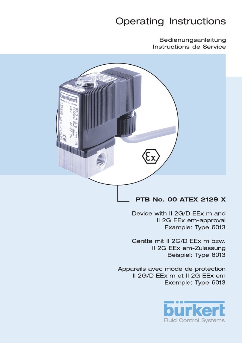
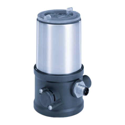
Burkert 8681 User manual

Operating Instructions
Type 8681
Control Head
Designs: 24 V DC, 120 V AC, AS-i,
DeviceNet, IO-Link, büS/CANopen

We reserve the right to make technical changes without notice.
Technische Änderungen vorbehalten.
Sous resérve de modication techniques.
© Bürkert Werke GmbH, 2010 - 2020
Operating Instructions 2004/07_EN_00806150 / Original DE

3
Control Head Type 8681
Contents
1 OPERATING INSTRUCTIONS ..............................................................................................................10
1.1 Symbols......................................................................................................................................10
1.2 Denitionofterms:“device”and“büS”....................................................................................10
2 AUTHORISED USE ...............................................................................................................................11
3 BASIC SAFETY INSTRUCTIONS .........................................................................................................12
4 GENERAL INFORMATION....................................................................................................................14
4.1 Contactaddress.........................................................................................................................14
4.2 Warranty .....................................................................................................................................14
4.3 Informationandinstructionson the Internet ............................................................................14
5 SYSTEM DESCRIPTION.......................................................................................................................15
5.1 Intendedapplicationarea..........................................................................................................15
5.2 Generaldescription....................................................................................................................15
5.3 Functions/options/variants....................................................................................................16
5.3.1 Structure of the control head..........................................................................................16
5.3.2 Fluid diagrams Type 8681 – examples............................................................................17
5.3.3 Number of solenoid valves .............................................................................................18
5.3.4 Pneumatic interfaces ......................................................................................................19
5.3.5 Magnetic and mechanical manual override....................................................................19
5.3.6 Position measuring system.............................................................................................19
5.3.7 Other features.................................................................................................................20
6 TECHNICAL DATA ................................................................................................................................21
6.1 Operatingconditions .................................................................................................................21
6.2 Conformity/standards..............................................................................................................21
6.3 Type label ..................................................................................................................................22
6.4 Additionalwarningsigns ...........................................................................................................23
6.5 Mechanicaldata.........................................................................................................................24
6.6 Pneumaticdata.......................................................................................................................... 26
6.7 Positionmeasuringsystemdata ...............................................................................................27
english
Control Head Type 8681

4
6.8 Factorysettingsinthermware................................................................................................28
6.8.1 Feedbackelds(positionmeasuringsystem).................................................................28
6.8.2 Service/maintenancenotication(maintenancerequest).............................................29
6.8.3 Manualoverridefunction(magnetic) ..............................................................................29
6.9 Resettingthedevice(DeviceReset) .........................................................................................30
7 ASSEMBLY ...........................................................................................................................................31
7.1 Safetyinstructions .....................................................................................................................31
7.2 Assemblyofthecontrolhead....................................................................................................31
7.2.1 Hubange/Adapter ......................................................................................................32
7.2.2 Assemblysequenceontheexampleofadouble-seatedvalve .....................................33
7.2.3 Realignment of the control head ....................................................................................33
7.2.4 Assembly of the pneumatic and electrical connections .................................................33
7.2.5 Recommended auxiliary materials..................................................................................34
8 OPENING AND CLOSING THE HOUSING ...........................................................................................35
8.1 Safetyinstructions .....................................................................................................................35
8.2 Openingandclosingthehousing .............................................................................................35
8.2.1 Opening the housing ......................................................................................................35
8.2.2 Closing the housing........................................................................................................36
9 PNEUMATIC INSTALLATION................................................................................................................37
9.1 Safetyinstructions .....................................................................................................................37
9.2 Pneumaticconnectionofthecontrolhead ..............................................................................37
9.3 Flowrestrictionfunctionofthesolenoidvalves.......................................................................38
10 24VDC-DESIGN................................................................................................................................ 40
10.1 Electricalconnectionoptions...................................................................................................40
10.2 Electricaldata ............................................................................................................................40
10.3 Designaid...................................................................................................................................42
10.4 Safetyinstructions .....................................................................................................................43
10.5 Electricalinstallation/start-up .................................................................................................43
10.5.1 Cable gland with screw terminals...................................................................................43
10.5.2 Multi-pole connection.....................................................................................................46
english
Control Head Type 8681

5
11 120VAC-DESIGN .............................................................................................................................47
11.1 Electricalconnectionoptions...................................................................................................47
11.2 Electricaldata ............................................................................................................................47
11.3 Designaid...................................................................................................................................48
11.4 Safetyinstructions .....................................................................................................................49
11.5 Electricalinstallation/start-up .................................................................................................50
12 ASINTERFACE-DESIGN....................................................................................................................53
12.1 Denition ....................................................................................................................................53
12.2 ElectricalconnectionoptionsforASinterface........................................................................54
12.3 Numberofconnectablecontrolheads .....................................................................................54
12.4 Maximumlengthofthebusline ................................................................................................54
12.5 Electricaldata ............................................................................................................................55
12.6 Designaid...................................................................................................................................57
12.7 Safetyinstructions .....................................................................................................................58
12.8 ElectricalinstallationoftheASinterface..................................................................................59
12.9 Programmingdata .....................................................................................................................61
13 DEVICENET-DESIGN .........................................................................................................................62
13.1 Denition ....................................................................................................................................62
13.2 Electricalconnectionoption.....................................................................................................62
13.3 DeviceNetspecication.............................................................................................................62
13.3.1 TotallinelengthandmaximumlinelengthaccordingtoDeviceNetspecication .........63
13.3.2 Drop line length...............................................................................................................63
13.4 Electricaldata ............................................................................................................................64
13.5 Safetypositionifthebusfails ...................................................................................................64
13.6 Designaid...................................................................................................................................65
13.7 Safetyinstructions .....................................................................................................................66
13.8 Electricalinstallation-DeviceNet .............................................................................................66
13.9 NetworktopologyofaDeviceNetsystem ................................................................................68
13.10ConguringtheDeviceNetaddress/baudrate.......................................................................68
13.10.1Settings of the DeviceNet address .................................................................................69
13.10.2Setting the baud rate ......................................................................................................70
english
Control Head Type 8681

6
13.11Congurationoftheprocessdata ............................................................................................70
13.11.1Static input assemblies...................................................................................................70
13.11.2Static output assembly...................................................................................................71
13.12Congurationofthedevice .......................................................................................................71
13.12.1Congurationofthesafetypositionofsolenoidvalvesduringabuserror ....................71
13.12.2Congurationexample...................................................................................................72
13.13DisplayofthestatusLEDsintheeventofabuserror.............................................................73
13.13.1Status of the device status LED "Modules" ...................................................................73
13.13.2Status of bus status LED "Network" ..............................................................................74
14 IO-LINK-DESIGN ................................................................................................................................75
14.1 Networkprinciple/interfaces ...................................................................................................75
14.2 QuickstartforType8681IO-Link...............................................................................................76
14.3 Technicaldata/specication....................................................................................................76
14.4 IO-Linkmaster/communication/conguration...................................................................... 77
14.5 Electricaldataformthecontrolhead(IO-Link).........................................................................77
14.5.1 Electrical connection options / interface ........................................................................77
14.5.2 Electrical data of the control head..................................................................................78
14.5.3 Design aid.......................................................................................................................80
14.5.4 Electrical installation – IO-Link .......................................................................................82
14.5.5 Pinassignment(portclassAorB)..................................................................................83
14.6 Software/rmwareupdates .....................................................................................................84
14.6.1 Software..........................................................................................................................84
14.6.2 Firmware updates ...........................................................................................................84
14.7 Safetypositionifthebusfails ...................................................................................................84
15 BÜS/CANOPEN-DESIGN ....................................................................................................................85
15.1 Denition ..................................................................................................................................85
15.2 Networkprinciple/Interfaces ...................................................................................................85
15.3 QuickstartforType8681büS/CANopen...................................................................................87
15.4 büS/CANopenspecication ......................................................................................................88
15.4.1 General data ...................................................................................................................88
15.4.2 Total line length and drop line lengths of the bus cables ...............................................88
15.5 Electricalconnectionoptions.................................................................................................... 89
15.6 Electricaldataofthecontrolhead............................................................................................89
english
Control Head Type 8681

7
15.7 Safetypositionifthebusfails ...................................................................................................90
15.8 Designaid...................................................................................................................................91
15.9 Installation–Safetyinstructions ...............................................................................................92
15.10Gateway.....................................................................................................................................92
15.11Gatewayinstallation...................................................................................................................92
15.12Electricalinstallation-büS/CANopen......................................................................................93
15.12.1Electronic module büS/CANopen: .................................................................................94
15.12.2Terminalstripconguration: ...........................................................................................94
15.12.3Details on the DIP switches for colour coding:...............................................................94
15.13NetworktopologyofabüS/CANopen system ..........................................................................95
15.14ConguringtheNodeID/baudrate......................................................................................... 95
15.14.1Setting the baud rate ......................................................................................................96
15.14.2SettingthebüS/CANopenaddress(NodeID) ................................................................97
15.14.3Factorysettingsofthecontrolheadregardingthegatewayconguration ....................99
15.14.4Centralcongurationmanagement(Congurationclient) ............................................100
15.15ChangingthegatewayIPaddress .........................................................................................100
15.15.1Changing the gateway IP address using web server ...................................................100
15.15.2ChangingthegatewayIPaddressusing“BürkertCommunicator” .............................102
15.15.3Changing the gateway IP address via Logix Designer .................................................103
15.15.4Changing the gateway IP address using RS Linx.........................................................106
15.16RegistrationofagatewayviaLogixDesigner ........................................................................107
15.17InstallationofagatewayviaLogixDesigner ..........................................................................108
15.18Congurationofthecontrolheadnetwork.............................................................................110
15.18.1“Hidefunction”viasoftware“LogixDesigner”............................................................110
15.18.2“Hidefunction”via“BürkertCommunicator” ..............................................................111
15.19Descriptionofthe(cyclical)I/Odata.......................................................................................113
15.20Accesstoparameters(Read/Write) ......................................................................................114
15.20.1Parameter – reading via Logix Designer .......................................................................114
15.20.2Parameters – writing via Logix Designer.......................................................................116
15.20.3AccesstoparametersviaBürkertCommunicator........................................................116
15.20.4Accesstofurtherparameters(cyclicandacyclic) ........................................................117
15.21DisplayofthestatusLEDsforbuserror.................................................................................118
15.22Firmwareupdates ....................................................................................................................119
english
Control Head Type 8681

8
16 ACCESSORIESFORBÜSDEVICES..................................................................................................120
17 CABLINGEXAMPLES(BÜS/CANOPEN) ..........................................................................................122
18 CONNECTION OF AN EXTERNAL INITIATOR ...................................................................................125
19 SPECIAL DESIGNS ............................................................................................................................127
19.1 Controlheadfordouble-actingactuators ..............................................................................127
19.1.1 Anomalies .....................................................................................................................127
19.1.2 Fluid diagram ...............................................................................................................127
19.1.3 Activation of a double-acting actuator .........................................................................127
19.2 Controlhead(AS-i)with2externalinitiators ..........................................................................128
19.2.1 Anomalies .....................................................................................................................128
19.2.2 Electrical installation and programming data ...............................................................128
20 POSITION MEASURING SYSTEM .....................................................................................................129
20.1 Settingthepositionmeasuringsystem(Teachprocedure)....................................................130
20.2 Teachbuttons/Teachfunctions ............................................................................................131
20.2.1 Teach functions and Teach reset ..................................................................................131
20.2.2 AutomaticTeachfunctions(Autotune)..........................................................................132
20.2.3 SequenceoftheautomticTeachfunctions(Autotune).................................................133
21 LED COLOUR ASSIGNMENTS ..........................................................................................................136
21.1 Displaymodi–overview..........................................................................................................136
21.1.1 DevicespecicLEDmode“8681ClassicMode”.........................................................138
21.1.2 NAMUR mode...............................................................................................................139
21.1.3 Valve mode ...................................................................................................................140
21.1.4 Valve mode + Errors .....................................................................................................141
21.1.5 Valve mode + Errors + Warnings ..................................................................................142
21.1.6 Displaymode“Fixedcolour”........................................................................................143
21.2 Flashingpattern&faultsignalling...........................................................................................143
21.2.1 Position feedback in normal operation .........................................................................143
21.2.2 Feedback in case of errors / warnings..........................................................................144
21.2.3 Localisation function.....................................................................................................147
21.3 Signalpriorities ........................................................................................................................148
21.3.1 When several statuses overlap for one valve ..............................................................148
21.3.2 When position feedback overlaps ...............................................................................148
english
Control Head Type 8681

9
22 SERVICEMODE/MANUALOVERRIDE...........................................................................................151
22.1 Magneticmanualoverride.......................................................................................................151
22.2 Mechanicalmanualoverride ...................................................................................................152
23 MAINTENANCE, TROUBLESHOOTING.............................................................................................153
23.1 Safetyinstructions ...................................................................................................................153
23.2 Safetypositions .......................................................................................................................154
23.3 Maintenance/service..............................................................................................................155
23.4 Cleaning....................................................................................................................................155
23.5 Malfunctions.............................................................................................................................155
24 REPLACEMENT OF COMPONENTS AND MODULES......................................................................157
24.1 Safetyinstructions ...................................................................................................................157
24.2 Changingtheelectronicmodule .............................................................................................158
24.3 Changingthevalves ................................................................................................................159
24.4 Changingthepositionmeasuringsystem ..............................................................................160
25 SHUTDOWN .......................................................................................................................................163
25.1 Safetyinstructions ...................................................................................................................163
25.2 DismantlingthecontrolheadType8681 ................................................................................163
26 PACKAGINGANDTRANSPORT........................................................................................................164
27 STORAGE ...........................................................................................................................................164
28 DISPOSAL ..........................................................................................................................................164
english
Control Head Type 8681
10
Operating Instructions
1 OPERATING INSTRUCTIONS
The operating instructions describe the entire life cycle of the device. Keep these instructions in a location which
is easily accessible to every user, and make these instructions available to every new owner of the device.
WARNING!
The operating instructions contain important safety information!
`Carefully read these instructions.
`Observe in particular the safety instructions, intended use and operating conditions.
`Persons, who work on the device, must read and understand these instructions.
1.1 Symbols
DANGER!
Warns of an immediate danger!
`Failure to observe the warning will result in a fatal or serious injury.
WARNING!
Warns of a potentially dangerous situation!
`Failure to observe the warning may result in serious injuries or death.
CAUTION!
Warns of a possible danger!
`Failure to observe this warning may result in a moderate or minor injury.
NOTE!
Warns of damage to property!
`Failuretoobservethewarningmayresultindamagetothedeviceortheequipment.
Indicates important additional information, tips and recommendations.
`Designates an instruction for risk prevention.
→Designates a procedure which you must carry out.
1.2 Denition of terms: “device” and “büS”
Theterm“device”usedinthismanualgenerallydenotestheControlheadType8681in its several designs
and variants.
Theterm“büS”(Bürkertsystembus)usedinthismanualstandsforthecommunicationbusdevelopedby
Bürkert,basedontheCANopenprotocol.
english
Control Head Type 8681
11
Authorised Use
2 AUTHORISED USE
Incorrect use of the control head Type 8681 may be dangerous to people, nearby equipment and
the environment.
The control head is designed for use as a control unit for pneumatically actuated process valves
and / or for recording their switching statuses.
`Use the device for its intended purpose only! Non-intended use of the device may be dangerous to
people,nearbyequipmentandtheenvironment.
`Usethedeviceaccordingtotheauthoriseddata,operatingconditionsandconditionsofusespeciedin
the contract documents and operating instructions. These are described in chapter “6TechnicalData”.
`In view of the large number of application options, check and, if necessary, test prior to installation
whetherthecontrolheadissuitableforthespecicapplicationcase:
Shouldyouhaveanyquestions,pleasecontactyourBürkertServiceCenter.
`DonotusepulsatingDCvoltage(rectiedACvoltagewithoutsmoothing)astheoperatingvoltage.
`Use the device only in conjunction with third-party devices and components recommended and autho-
risedbyBürkert.
`Any unauthorised reconstructions and changes to the control head are prohibited for safety reasons.
`Correct transportation, correct storage and installation as well as careful operation and maintenance are
essential for reliable and problem-free operation.
`For connecting the control head, use line installations that do not cause any mechanical stresses.
`Inhazardousareas(potentiallyexplosiveatmosphere),onlyusedevicesthatareapprovedforthisarea.
Thesedevicesareidentiedbyaseparate„Ex“typelabel.Foruse,observetheinformationonthe
separate„Ex“typelabelandtheadditionalinstructions(ATEX)–todownloadfromtheBürkertweb-
site–see„4.3InformationandinstructionsontheInternet“onpage14.
`Devices without a separate Ex type label must not be used in the potentially explosive atmosphere..
english
Control Head Type 8681
12
Basic Safety Instructions
3 BASIC SAFETY INSTRUCTIONS
These safety instructions do not consider any contingencies or incidents which occur during installation,
operation and maintenance.
Theoperatorisresponsibleforobservingthelocation-specicsafetyregulations,alsowithreferencetothe
personnel.
DANGER!
Danger of explosion in a potentially explosive atmosphere (only in the event of a fault as zone 2)!
`Opening the hood or the housing in a potentially explosive atmosphere is only allowed in a not energised
state!
`Secure the housing with a lead seal to prevent it from being opened without a tool!
`ActivatingtheDIPswitchesonthePCB,usingtheserviceinterfaceandtheTeachbuttons,isnot per-
mitted in a potentially explosive atmosphere!
`Layers of dust on the housing may not exceed 5 mm! Lint, conductive and non-conductive dust par-
ticles are allowed. The inside of the housing must not be dirty!
`When wiping the control head, use a damp or anti-static cloth in the potentially explosive atmosphere to
prevent electrostatic charges!
`Use only cables and cable glands which have been approved for the respective application area and
which have been screwed into place according to the respective installation instructions!
`Close all unnecessary openings with locking screws/sealing plugs approved for explosions area!
WARNING!
Danger – high pressure in the plant / at the device!
`Beforelooseninglinesandvalves,turnothepressureandventthelines.
Risk of electric shock!
`Beforereachingintothesystem(exceptfortheTeachprocedureinanon-explosiveatmosphere)switch
othepowersupplyandsecureittopreventrestarting!
`Observeapplicableaccidentpreventionandsafetyregulationsforelectricalequipment!
General hazardous situations.
To prevent injuries:
`Operate the device only in perfect status and in consideration of the operating instructions.
`Observe the general rules of technology.
`Install the device according to the regulations applicable in the respective country.
`Only trained technicians may perform installation and maintenance work.
`Perform installation and maintenance with suitable tools only.
`Do not make any unauthorised internal or external changes to the device!
`Ensure that the system cannot be activated unintentionally.
`Aftertheprocessisinterrupted,restartinacontrolledmanner.Observesequence:rstconnectelectri-
cal or pneumatic power supply, than charge the device with medium.
english
Control Head Type 8681
13
Basic Safety Instructions
NOTE!
Electrostatic sensitive components/modules!
•Thedevicecontainselectroniccomponentswhichreactsensitivelytoelectrostaticdischarge(ESD).Contact
with electrostatically charged persons or objects may be hazardous to these components. In the worst
case scenario, they will be destroyed immediately or will fail after start-up.
•ObservetherequirementsinaccordancewithEN61340-5-1tominimiseoravoidthepossibilityofdamage
caused by sudden electrostatic discharge!
•Also ensure that you do not touch electronic components when the operating voltage is on!
NOTE!
Risk of damage to property!
•Do not connect any mechanically rigid connection parts, in particular those with long lever arms, as
suchconnectionscouldgeneratetorquesthatmightdamagethecontrolhead.
•Donotsupplythemediumconnectionsofthesystemwithliquidsoraggressiveorammablemedia!
•Donotsubjectthehousingtomechanicalloads(e.g.byplacingobjectsonitorstandingonit).
•Do not make any external changes to the housings of the device. Do not paint housing parts or screws.
•Only use compatible cleaning agents for cleaning the securely closed control head and always rinse
thoroughly with clean water.
english
Control Head Type 8681
14
General Information
4 GENERAL INFORMATION
4.1 Contact address
Bürkert Fluid Control Systems
Sales Center
Christian-Bürkert-Straße13-17
D-74653Ingelngen,Germany
Phone: +49 7940 10 91 111
Fax: +49 7940 10 91 448
Website: www.burkert.com
4.2 Warranty
Thewarrantyisonlyvalidifthecontrolheadisusedasintendedinaccordancewiththespeciedappli-
cation conditions.
4.3 Information and instructions on the Internet
The operating instructions, data sheets, software manuals and additional instructions for control head Type
8681 in its several designs and variants can be found on the Internet at:
www.burkert.com
Software can also be downloaded for the respective variants.
To do so, enter the type number ortheidentication/articlenumberoftherespectivedevicein the search
eldanddownloadtherequiredlesunder“Downloads” or “Downloads”/ ”Software” .
TheEDSlesforDeviceNetandbüS/CANopenaswellastheIODDleforIO-LinkaresavedintheZIP
container“InitiationFiles”.Customer-specicsoftwareisonlyaccessibleviathecustomerlogin(e.g.data
forthepreconguredME43gateway).
Additional documents for the conguration ofthevariants“IO-Link”and“büS/CANopen”canalsobe
found on the website either under Type 8681 or the respective type number, e. g.:
•Softwaremanual|Centralcongurationmanagement
•Operating instructions Type ME43 | Fieldbus gateway büS to Industrial Ethernet
•SoftwaremanualType8920|BürkertCommunicator
english
Control Head Type 8681

15
System Description
5 SYSTEM DESCRIPTION
5.1 Intended application area
The control head Type 8681 has been designed for use as an actuator for pneumatically operated process
valves and / or for recording the switching status of these.
5.2 General description
The control head Type 8681 is used for actuating pneumatically operated process valves.
Forprocessvalveactuation,thecontrolheadcanbeequippedwithuptothreesolenoidvalves.
For the recording and feedback of the process valve switching positions to a higher-level control, the control
headhasbeenequippedwithacontact-freepositionmeasuringsystemwhichoperateswith3discrete,
adjustablefeedbacksignals(Teachfunctions).
The control head and the process valve are interconnected by an adapter. This produces an integrated,
compact and decentralised system of feedback, actuation and valve function. The following advantages
over centralised solutions working with valve clusters are achieved:
•low installation expenditure
•easy start-up
•higherapplication-specicexibility
•shorter switching times and less air consumption due to shorter distances between the pilot valves and
the process valve. Up to 3 solenoid valves in the control head serve as pilot valves.
Various pneumatic and electrical connection or communication variants are available, and described in
detail below.
english
Control Head Type 8681

16
System Description
5.3 Functions / options / variants
5.3.1 Structure of the control head
Electronic module with
connection terminals,
service interface and
Teachbuttons(rear
side)
Solenoid valve V3 *)
Solenoid valve V1 *)
Solenoid valve V2 *)
Cable glands
(rear)
Exhaustairconnection(3/R)
Mechanical manual override
(redlever)
Supplypressureconnection(1/P)
Working connections
(2/A1...3)
Flowrestrictionscrew(s)for
PandR(2persolenoidvalve)
Solenoidvalve3(2/A3)
Solenoidvalve2(2/A2)
Solenoidvalve1(2/A1)
Position measuring system with
LED(devicestatusLED/TopLED)
Silencer in the exhaust air
connection(3/R),notshown
Sealing lug
(onlowerhousingpart)
2lockingscrews
(shoulderscrewsM5).
No sealing function,
merely as protection
againstpullingofrom
thehubange
Lockinggroove(3x)
Fig. 1: Structure of control head Type 8681 (with 3 solenoid valves)
____________________________________________
*) If the solenoid valve is not present, the connection is sealed tightly with a cover plate.
Controlheadversionswithoutsolenoidvalves(i.e.“feedbacktop”)donothaveanypneumaticconnec-
tions at the housing, see also chapter “5.3.3Numberofsolenoidvalves” and “Fig.5”.
english
Control Head Type 8681

17
System Description
5.3.2 Fluid diagrams Type 8681 – examples
Thefollowinguiddiagramsshowtheinternalpneumaticcircuitryofthesolenoidvalvesofthecontrolhead
to the process valve being controlled.
Variant with 3 solenoid valves – e.g. for double-seated (process) valves:
withrestrictioncapabilityforeachsolenoidvalve(Type6524,see“Fig.6”onpage26)
Process
valve
Solenoid valves
Type 6524
Fig. 2: Fluid diagram (model: 3 solenoid valves Type 6524)
english
Control Head Type 8681

18
System Description
Variant with 2 solenoid valves – e.g. for double-acting actuators:
-withrestrictioncapabilityforeachsolenoidvalve(Type6524,see“Fig.6”onpage26)
- for safety position: solenoid valve V1 as NC valve, solenoid valve V2 as NO valve
- see also chapter “19Specialdesigns”onpage127
Process valve
up /
open
down /
close
Fig. 3: Fluid diagram (design for double-acting actuators: 2 solenoid valves, NC* + NO** )
5.3.3 Number of solenoid valves
Depending on the number of solenoid valves in the control head, the control head can control various
processvalves(single-acting and double-acting actuators as well as double-seated and multi-position
valves)oractasamerefeedbacktopwithoutsolenoidvalves:
Type of use Number of solenoid valves
Feedback top 0
Control head for single-acting actuators 1(NC*)
Control head for double-acting actuators
(bothdrivechambersnotenergisedanddeaerated) 2(2xNC*)
Control head for double-seated valves with integrated aeration of both
valve seats 3(3xNC*)
Controlheadfordouble-actingactuators(withsafetyposition)–for
details see chapter “19Specialdesigns” 2(1xNC*+1xNO**)
1
* NC = 3/2-way valve; closed in rest position, output A relieved
** NO = 3/2-way valve; opened in rest position, output A pressurised
english
Control Head Type 8681

19
System Description
5.3.4 Pneumatic interfaces
•Intake & exhaust air connections (1/P,3/R): G 1/4
Working connections (2/A1...A3): G 1/8
•Integrated non-return valves in the solenoid valves' exhaust air duct
•ActuationofConnection2/A1(SolenoidValve1;normallythemainstrokeoftheprocessvalve)usingthe
magnetic manual override that is externally accessible via magnetic manual override tool.
(bothsolenoidvalvesareactuatedsimultaneouslyvia magnetic manual override tool for the design for
double-actingactuators)
•Specialsilencerswithahighow-ratecapacitytoconnection3/Rhavealreadybeenmounted.
•The interior of the housing is protected against excessive overpressure, for example due to leakages, by a
pressure-relief valve with output into the joint exhaust air connection 3/R.
5.3.5 Magnetic and mechanical manual override
The control head provides the following as standard:
•Magnetic manual override for solenoid valve V1 (via magnetic manual override tool)::
easilyaccessiblefromtheoutside,onthebasisofencodedmagneticeldsforSolenoidValveV1(Con-
nection2/A1)aswellas
•Mechanical manual override:
oneachequippedsolenoidvalve,accessiblewhenthehoodisopen(see“Fig.6”onpage26)
The magnetic manual override (for 2/A1 or V1) has the following advantages:
•the control head does not need to be opened
•simpleactuationtoolforopening/closingsolenoidvalveV1(mainstroke)-
helpful for service/maintenance work on the process valve (V2andV3areswitchedoatthesametime;
both solenoid valves are actuated simultaneously with the magnetic manual override tool for the design
fordouble-actingactuators)
•LEDdisplayforthe"activated(magnetic)manualoverride"status=servicemode
(seechapters“21LEDColourAssignments” and “22ServiceMode/Manualoverride”)
Magnetic manual override is only applicable in automatic mode; in manual mode, V1 cannot be
switched using the magnetic manual override tool.
For a detailed description of the manual override, see chapter “22ServiceMode/Manualoverride”.
5.3.6 Position measuring system
The switching positions of the process valves are reported to the actuator by feedback signals from the
inductive position measuring system.
The connection to the control head is done by means of a simple adaptation to the process valve's piston
(valvespindle).Detailsaredescribedinchapters“6.7Positionmeasuringsystemdata”onpage27 and
“20PositionMeasuringSystem”onpage129.
english
Control Head Type 8681

20
System Description
5.3.7 Other features
•Centralopticalpositionindicator(devicestatusLED/TopLED)forshowingtheprocessvalveswitching
positions:
Positionsandstatusinformationaregenerallyindicatedby3signalcoloursofthedevicestatusLED(Top
LED),additionalcoloursanddisplaymodes(e.g.NAMUR)areavailableforthebüS/CANopenandthe
IO-Link design.
Theassignmentofthesignalcoloursandthe“ashingpatterns”indicatingthestatusortypeoferrorare
described in detail in chapter “21LEDColourAssignments”.
•Simpleadaptationofthecontrolhead(positionmeasuringsystem)totheprocessvalvepistonrod/valve
spindle
•Simpleadjustmentofthepositionmeasuringsystem by means of 3 Teach buttons on the electronic
module–eithermanualorautomaticadjustment(manualTeachfunctionorautomaticTeachfunction
(Autotune))-seechapter“20.2”onpage131
•Thecapabilityofrestrictingthepilotvalves(solenoidvalves)for the individual setting of the expansion
andretractionratesoftheprocessvalveandtheindividualsettingoftheow-rateoftheworkingconnec-
tions(see“Fig.6”onpage26)
•Energyecientsolenoidvalveactuationby lowering the holding current during long-term operation
•Variouselectricalconnectionandcommunicationoptions(24VDC,120VAC,AS-Interface,DeviceNet,
IO-Link,büS/CANopen-seetherespectivechapter)
english
Control Head Type 8681
Other manuals for 8681
5
Table of contents
Other Burkert Industrial Equipment manuals

Burkert
Burkert 8695 Series User manual

Burkert
Burkert 6519 User manual

Burkert
Burkert PTB 14 ATEX 2023 X User manual

Burkert
Burkert AC10 5-PD47 Series User manual

Burkert
Burkert AC19 User manual

Burkert
Burkert MP05 User manual

Burkert
Burkert buS User manual

Burkert
Burkert 8644 AirLINE User manual

Burkert
Burkert 6105 User manual

Burkert
Burkert 6104 User manual