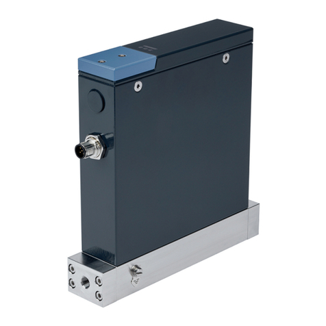
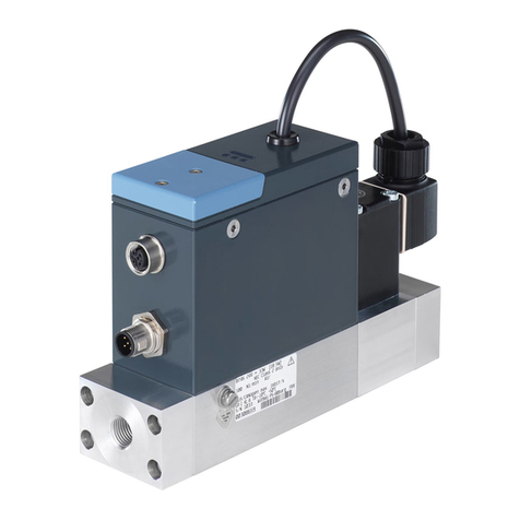
Burkert 8743 User manual

Type 8743
Mass flow meter / Mass flow controller
Operating Instructions

We reserve the right to make technical changes without notice.
© Bürkert Werke GmbH & Co. KG, 2023
Operating Instructions 2304/00_EUen 00572427 / Original EN

Type 8743
Table of contents
3
TABLE OF CONTENTS
1 About this document..................................................................................................................................6
1.1 Manufacturer .................................................................................................................................... 6
1.2 Used symbols................................................................................................................................... 6
1.3 Terms and abbreviations .................................................................................................................. 7
2 Safety instructions......................................................................................................................................8
2.1 Intended use..................................................................................................................................... 8
2.2 Safety................................................................................................................................................ 8
3 Product description..................................................................................................................................11
3.1 Product overview............................................................................................................................ 11
3.2 Product identification ..................................................................................................................... 13
3.2.1 Type label...........................................................................................................................13
3.2.2 Calibration label .................................................................................................................14
3.2.3 Conformity marking ...........................................................................................................14
3.2.4 Symbols and markings on device......................................................................................14
3.3 Display elements ............................................................................................................................ 14
3.3.1 Status indicator..................................................................................................................14
3.3.2 NAMUR mode....................................................................................................................15
3.3.3 Network status indicator....................................................................................................16
3.3.4 Communication indicator...................................................................................................16
3.4 Functionality ................................................................................................................................... 16
3.4.1 büS interface......................................................................................................................16
3.4.2 Actuator is a control valve .................................................................................................17
3.4.3 Memory card......................................................................................................................17
4 Technical data ..........................................................................................................................................18
4.1 Standards and Directives ............................................................................................................... 18
4.2 Operating conditions ...................................................................................................................... 18
4.3 Medium........................................................................................................................................... 18
4.3.1 Quality of the medium........................................................................................................19
4.3.2 Pressure loss .....................................................................................................................20
4.4 Electrical data ................................................................................................................................. 21
4.5 Communication .............................................................................................................................. 23
4.6 Mechanical data ............................................................................................................................. 23
5 Medium connection..................................................................................................................................24
5.1 Possible medium connections ....................................................................................................... 24
5.2 Installation procedure ..................................................................................................................... 24
5.2.1 G-internal-threaded connections.......................................................................................24
5.2.2 NPT-internal-threaded connections ..................................................................................26
5.2.3 Flange connections............................................................................................................26
6 Electrical connection................................................................................................................................28
6.1 Additional documentation .............................................................................................................. 28
6.2 Wire the variant Analogue with D-sub DE-9 male connector......................................................... 28
6.2.1 Digital input ........................................................................................................................29
Type 8743
Table of contents
4
6.2.2 Relay output.......................................................................................................................30
6.3 Wire the variant Analogue with a 6-pin terminal strip..................................................................... 31
6.4 Wire the variant Industrial Ethernet ................................................................................................ 32
6.5 Connect the functional earth .......................................................................................................... 33
7 Commissioning.........................................................................................................................................35
7.1 Commissioning procedure ............................................................................................................. 35
8 Configuration with Bürkert Communicator .............................................................................................36
8.1 Setting tools.................................................................................................................................... 36
8.2 Connect to the Bürkert Communicator .......................................................................................... 36
8.3 Setting the Industrial Ethernet address .......................................................................................... 37
8.4 Functions ........................................................................................................................................ 37
8.4.1 Shut-off threshold ..............................................................................................................37
8.4.2 Flush mode ........................................................................................................................37
8.5 Change of medium ......................................................................................................................... 38
8.6 User-defined adjustment ................................................................................................................ 38
8.7 Zero point adjustment .................................................................................................................... 38
8.8 Set-point sources and operation modes........................................................................................ 38
8.9 Operation modes of an MFC .......................................................................................................... 39
8.10 Normal operation mode.................................................................................................................. 40
8.10.1 Analogue variant ................................................................................................................41
8.10.2 Industrial Ethernet variant ..................................................................................................41
8.11 Optimise the closed-loop control parameters................................................................................ 41
8.12 Choose the source that gives the set-point value.......................................................................... 42
8.13 Set-point values without communication ....................................................................................... 43
9 Maintenance .............................................................................................................................................44
9.1 Inspect and clean the stainless steel mesh-filter............................................................................ 44
9.2 Cleaning and recalibration at the factory........................................................................................ 44
9.3 Replace the memory card .............................................................................................................. 45
10 Troubleshooting .......................................................................................................................................46
10.1 Status indicator is red..................................................................................................................... 46
10.2 Status indicator is orange............................................................................................................... 46
10.3 Status indicator is yellow................................................................................................................ 47
10.4 Status indicator is blue ................................................................................................................... 47
10.5 Status indicator is off...................................................................................................................... 48
10.6 Status indicator flashes .................................................................................................................. 48
10.7 Status indicator goes out periodically ............................................................................................ 48
10.8 Replacement device adopts none of the values from the defective device................................... 48
10.9 Replacement device does not adopt all of the values from the defective device.......................... 48
10.10 No mass flow rate........................................................................................................................... 49
10.11 Unstable measured value ............................................................................................................... 49

Type 8743
Table of contents
5
10.12 Set-point value at 0 %, no mass flow, but a non-zero mass flow rate is measured...................... 50
10.13 Set-point value at 0 %, mass flows, and a mass flow rate is measured........................................ 50
10.14 Set-point value is not reached........................................................................................................ 50
10.15 Network status indicator ................................................................................................................ 50
11 Spare parts and accessories ...................................................................................................................52
11.1 Electrical accessories ..................................................................................................................... 52
11.2 Compression fittings for a device with G-internal-threaded connections...................................... 52
11.3 Mesh filters ..................................................................................................................................... 52
11.4 Additional software......................................................................................................................... 53
12 Uninstallation ............................................................................................................................................54
12.1 Dismantling..................................................................................................................................... 54
13 Logistic .....................................................................................................................................................55
13.1 Transport ........................................................................................................................................ 55
13.2 Storage ........................................................................................................................................... 55
13.3 Return ............................................................................................................................................. 55
13.4 Disposal .......................................................................................................................................... 55

Type 8743
About this document
6
1 ABOUT THIS DOCUMENT
The document is an important part of the product and guides the user to safe installation and operation.
The information and instructions in this document are binding for the use of the product.
Before using the product for the first time, read and observe the whole safety chapter.
Before starting any work on the product, read and observe the respective sections of the document.
Keep the document available for reference and give it to the next user.
Contact the Bürkert sales office for any questions.
Further information concerning the product at country.burkert.com.
1.1 Manufacturer
Bürkert Fluid Control Systems
Christian-Bürkert-Str. 13−17
D-74653 Ingelfingen
The contact addresses are available at country.burkert.com in the menu Contact.
1.2 Used symbols
DANGER!
Warns of a danger that leads to death or serious injuries.
WARNING!
Warns of a danger that can lead to death or serious injuries.
CAUTION!
Warns of a danger that can lead to minor injuries.
NOTICE!
Warns of property damage that can damage the product or the installation.
Indicates important additional information, tips and recommendations.
Refers to information in this document or in other documents.
Indicates a step to be carried out.
Indicates a result.
Menu Indicates a software user-interface text.

Type 8743
About this document
7
1.3 Terms and abbreviations
The terms and abbreviations are used in this document to refer to following definitions.
Device Type 8743
MFM Mass flow meter
MFC Mass flow controller
bar Unit for relative pressure

Type 8743
Safety instructions
8
2 SAFETY INSTRUCTIONS
2.1 Intended use
The device MFM is designed to measure the mass flow rate of clean and dry gases.
The device MFC is designed to measure and regulate the mass flow rate of clean and dry gases.
The permitted media are listed in Technical data [}18].
Prerequisites for safe and trouble-free operation are correct proper transportation, storage, installation,
start-up, operation and maintenance.
The instructions are part of the device. The device is intended exclusively for use within the scope of these
instructions. Uses of the device that are not described in these instructions, the contractual documents or
the type label can lead to severe personal injury or death, damage to the device or property and dangers for
the surrounding area or the environment.
Only trained and qualified personnel may install, operate and maintain the device. See qualification of
persons in Safety [}8]
Use the device only in conjunction with third-party devices and components recommended and author-
ized by Bürkert.
Use the device only when it is in perfect condition.
Only use the device indoors.
Do not open the device.
Do not mechanically load the device.
Do not use the device in high-vibration areas.
2.2 Safety
Qualification of personnel working with the device
Improper use of the device can lead to serious personal injury or death. To avoid accidents when working
with the device, the following minimum requirements must be met:
Carry out work on the device within the scope of these instructions in a safety-compliant manner.
Detect and avoid dangers when working on the device.
Understand the instructions and implement the information contained therein accordingly.
Responsibility of the operator
The operator is responsible for observing the location-specific safety regulations, also in relation to person-
nel.
Observe the general rules of technology.
Install the device according to the regulations applicable in the respective country.
The operator must make hazards arising from the location of the device avoidable by providing appropri-
ate operating instructions.

Type 8743
Safety instructions
9
Changes and other modifications, spare parts and accessories
Changes to the device, incorrect installation or use of non-approved devices or components create hazards
that can lead to accidents and injuries.
Do not make any changes to the device.
Do not mechanically load the device.
Observe the operating instructions of the device or component used.
Only use the devices in conjunction with approved devices or components.
Spare parts and accessories that do not meet Bürkert’s requirements may impair the operational safety of
the device and cause accidents.
To ensure operational safety, only use original parts from Bürkert.
Operation only after proper transport, storage, installation, start-up or maintenance.
Improper transport, storage, installation, start-up or maintenance endanger the operational safety of the
device and can cause accidents. This can lead to serious personal injury or death.
Only carry out works which are described in these instructions.
Only carry out works using suitable tools.
Have all other works carried out by Bürkert only.
Technical limit values and media
Non-compliance with technical limit values or unsuitable media can damage the device and lead to leaks.
This can cause accidents and seriously injure or kill people.
Comply with limit values. See Technical data [}18] and information on the type label.
Only feed media into the media ports that are listed in the chapter Technical data [}18].
Observe the safety data sheet for the media used.
Medium under pressure
Medium under pressure can seriously injure people. In the event of overpressure or pressure surges, the
device or lines can burst. Pneumatic lines that are defective or not securely fastened can come loose and
swing around.
Before working on the device or system, switch off the pressure. Vent or empty the lines.
Adhere to the permitted pressure ranges of the medium.
Comply with the permitted temperature ranges of the medium.
Electric shock due to electrical components
Touching live parts can result in severe electric shock. This can lead to serious personal injury or death.
Before working on the device or system, switch off the power supply. Secure it against reactivation.
Observe any applicable accident prevention and safety regulations for electrical devices.
Working on the device
Working on the device that has not been powered down, unauthorised switching on or uncontrolled start-
up of the system can cause accidents. This can lead to serious personal injury or death.
Only work on the device when it is not in use.
Ensure that the device or system cannot be switched on unintentionally.

Type 8743
Safety instructions
10
Only start the process in a controlled manner following disruptions. Observe sequence:
1. Apply supply voltage or pneumatic supply.
2. Charge the device with medium.
Hot surfaces and fire hazard
The surface of the device can become hot with fast-switching actuators or with hot media.
Wear suitable protective gloves.
Keep highly flammable substances and media away from the device.
Electrostatically sensitive components and assemblies
The device contains electronic components that are susceptible to the effects of electrostatic discharging
(ESD). Components that come into contact with electrostatically charged persons or objects are at risk. In
the worst case scenario, these components will be destroyed immediately or fail after start-up.
Meet the requirements specified by EN61340-5-1 to minimise or avoid the possibility of damage caused
by a sudden electrostatic discharge.
Do not touch electronic components when the supply voltage is connected.

Type 8743
Product description
11
3 PRODUCT DESCRIPTION
The device is used for ultimate precision in the feedback control of medium.
This document describes following variant:
MFM Analogue
MFM Industrial Ethernet
MFC Analogue with proportional valve
MFC Industrial Ethernet with proportional valve
3.1 Product overview
MFM Analogue
1
234
5
6
7
8
Fig.1: Example of a MFM Analogue D-Sub
1 Status indicator (LED) 2 Flow direction
3 Base block 4 Functional earth connection
5 Medium connection 6 Electrical connection
7 büS interface 8 Slot for the memory card

Type 8743
Product description
12
MFM Industrial Ethernet
1
234
5
6
7
8
9
10
Fig.2: Example of a MFM Industrial Ethernet
1 Status indicator (LED) 2 Flow direction
3 Base block 4 Functional earth connection
5 Medium connection 6 Electrical connection
7 3-pin removable terminal strip 8 büS interface
9 Slot for the memory card 10 Communication indicator (LED)
MFC Analogue with proportional valve
1
2
345
6
7
8
9
Fig.3: Example of a MFC Analogue D-Sub with proportional valve
1 Status indicator (LED) 2 Proportional valve
3 Flow direction 4 Base block
5 Functional earth connection 6 Medium connection
7 Electrical connection 8 büS interface
9 Slot for the memory card

Type 8743
Product description
13
MFC Industrial Ethernet with proportional valve
1
2
345
6
7
8
910
Fig.4: Example of a MFC Industrial Ethernet
1 Status indicator (LED) 2 Proportional valve
3 Flow direction 4 Base block
5 Functional earth connection 6 Medium connection
7 Electrical connection 8 büS interface
9 Slot for the memory card 10 Communication indicator (LED)
3.2 Product identification
3.2.1 Type label
8743 24V 9W [5,5W]
IP20
5,0 Nl/min N2
10,0 Nl/min N2
IN/OUT 0-5 V
Ta=-10°C .. +50°C FKM
S/N 1000 W41ME PS=100barg
00******
1 2 3
4
5
6
7
8910
11
12
13
14
15
16
Fig.5: Example of type label Type 8743
1 Type 2 Operating voltage
3 Power consumption 4 Note: Observe the operating instructions
5 Medium 1 6 Medium 2
7 Sealing material 8 Burst pressure
9 Manufacture code 10 Article number
11 Serial number 12 Ambient temperature
13 Input and output 14 Nominal mass flow rate (Q nominal)
15 Nominal mass flow rate (Q nominal) 16 Degree of protection

Type 8743
Product description
14
3.2.2 Calibration label
Mass Flow Controller
Medium 1 Medium 2
P1: 1,00 barg P1: 1,00 barg
Mounting: horizontal upright
Id: 00******
QC passed: __ . __ . ____
1
2
3
4
5
6
Fig.6: Description of the calibration label
1 Variant 2 Calibration medium
3 Calibration pressure 4 Installation position
5 Article number 6 Calibration date
3.2.3 Conformity marking
1
2
3
Fig.7: Conformity label
1 CE marking 2 Certification marking for USA and/or
Canada
3 Warning hot surface
3.2.4 Symbols and markings on device
Earth terminal
Direct current
Industrial Ethernet variant
DC-B0-58-FF-FF-FF Example of marking of the MAC address
ETH 2
ETH 1
Marking of the Ethernet ports
3.3 Display elements
3.3.1 Status indicator
The status indicator changes its colour based on the NAMUR recommendation NE107. Refer to NAMUR
mode [}15].
The colour of the status indicator indicates:

Type 8743
Product description
15
Whether device diagnostics are active or not. Diagnostics are active on the device and cannot be deactiv-
ated.
If diagnostics are active, then the status indicator shows whether diagnostics events have been generated
or not. If several diagnostics events have been generated, then the status indicator shows the diagnostics
event with the highest priority.
If the status indicator flashes, then the device is selected in a man-machine interface such as the Bürkert
Communicator software.
To solve a problem indicated by the status indicator, refer to Troubleshooting [}46]
3.3.2 NAMUR mode
The status indicator shows the status of the device and its peripherals, based on NAMUR recommendation
107 (NR 107).
If various alerts are present, the status indicator always shines in the colour of the highest prioritised alert
(red = outage = highest priority).
Colour Colour
code
Status Description
red 5 Failure, error or fault Due to a malfunction in the device or its periphery, normal
operation is not possible.
orange 4 Function check Work is being carried out on the device, which means that
normal operation is temporarily not possible.
yellow 3 Out of specification The environment conditions or process conditions for the
device are not within the specified range. Internal device
diagnostics indicate problems within the device or with the
process properties.
blue 2 Maintenance required The device is in normal operation, although a function is
briefly restricted.
Service device
green 1 Diagnostics active Device is running faultlessly, diagnostics are active.
white 0 Diagnostics inactive Device is switched on, diagnostics are inactive.
Tab.1: Status indicator according to NE 107

Type 8743
Product description
16
3.3.3 Network status indicator
Industrial Ethernet variant
1
2
Fig.8: Location and description of the LED's of an RJ45 socket
1 Link/Act LED (green) 2 Link LED (yellow)
3.3.4 Communication indicator
Industrial Ethernet variant
This LED shows the status of the communication between the device and the PLC (Programmable Logical
Controller).
LED indicator Description Meaning
Green RUN Connection to the PLC is active.
Red ERROR Connection to the PLC is inactive.
Tab.2: Description of the communication indicator
3.4 Functionality
3.4.1 büS interface
The büS interface is used for short-term servicing of the device with the Bürkert Communicator.
The Bürkert Communicator runs under Windows. Refer to Connect to the Bürkert Communicator [}36]
The USB-büS-Interface set, available as an accessory, is necessary. Refer to Spare parts and accessories
[}52]

Type 8743
Product description
17
Fig.9: büS stick, inserted in the related connector of the device
3.4.2 Actuator is a control valve
MFC with proportional valve
The control valve is a direct-acting and normally-closed proportional valve.
The control valve provides the sealing function when the following conditions are met:
The device is used within the specified pressure range.
The device is equipped with a valve seat seal that is made of a soft material such as FKM, FFKM or
EPDM.
If the valve seat seal is made of a hard material such as PCTFE, then the control valve may not be
tight.
Valves with a seat size of 0.05mm or 0.1mm have a seat seal made of a hard material.
Unstable measured values may occur. Refer to Unstable measured value [}49]
3.4.3 Memory card
If the memory card is defective or has been lost, contact your Bürkert sales office to purchase a
new one.
The device is delivered with a memory card that is inserted in the device.
When the device is energised, there are two possibilities:
If device-specific data is stored on the inserted memory card, then the device adopts the data. At deliv-
ery, the memory card contains device-specific data. To get a list of the stored data, refer to the file Device
Description File that can be downloaded from country.burkert.com.
If the inserted memory card is empty, then the device loads its own data on the memory card. A new
memory card is empty.
The data on the memory card can be transferred to another device with the same article number. For ex-
ample, the data can be transferred from a defective device to a new device.

Type 8743
Technical data
18
4 TECHNICAL DATA
4.1 Standards and Directives
The device complies with the relevant EU harmonisation legislation. In addition, the device also complies
with the requirements of the laws of the United Kingdom.
The harmonised standards that have been applied for the conformity assessment procedure are listed in
the current version of the EU Declaration of Conformity/UK Declaration of Conformity.
4.2 Operating conditions
MFM
Ambient temperature −10°C...+40°C
Storage temperature −10°C...+70°C
Degree of protection IP20 according to EN60529 / IEC60529 (only with cables, plugs or
sockets connected correctly) determined by Bürkert, not evaluated
by UL
Medium temperature −10°C...+40°C
Medium Refer to the type label
Operating pressure max.10 bar
Relative ambient humidity Max.95% at 55°C (non-condensing)
MFC with proportional valve
Ambient temperature −10°C...+40°C
Storage temperature −10°C...+70°C
Degree of protection IP20 according to EN60529 / IEC60529 (only with cables, plugs or
sockets connected correctly) determined by Bürkert, not evaluated
by UL
Medium temperature −10°C...+40°C
Medium Refer to the type label
Operating pressure max.10 bar
Relative ambient humidity Max.95% at 55°C (non-condensing)
4.3 Medium
MFM
Calibration medium Nitrogen (N2)
Nominal flow range Qnom (reference
to N2 (lN/min))
0,01...100IN/min

Type 8743
Technical data
19
Turn-down ratio 1:20 (Qnom < 0,025lN/min)
1:50 (Qnom ≥ 0,025lN/min)
others on request
Repeatability ±0.1% of the full scale
Measurement accuracy, after
30minutes warm-up time
± 0.8% of the measured value
± 0.3% of the full scale
If the medium deviates from the calibration medium, the actual
measurement accuracy might vary from the value specified in the
data sheet.
Response time < 2s
MFC with proportional valve
Calibration medium Nitrogen (N2)
Nominal flow range Qnom (reference
to N2 (lN/min))
0,01...100IN/min
Turn-down ratio 1:20 (Qnom < 0,025lN/min)
1:50 (Qnom ≥ 0,025lN/min)
others on request
Repeatability ±0.1% of the full scale
Measurement accuracy, after
30minutes warm-up time
± 0.8% of the measured value
± 0.3% of the full scale
If the medium deviates from the calibration medium, the actual
measurement accuracy might vary from the value specified in the
data sheet.
Response time < 2s
4.3.1 Quality of the medium
The medium must be clean and dry.
NOTICE!
The gas or gas mixture must obey the quality criteria in the following table. The quality criteria are given in
standard ISO 8573-1, Compressed Air - Part 1: Contaminants and purity classes. The medium must obey
the quality criteria to obey the following requirements:
the necessary measurement accuracy of the device
to meet the safety requirements
to meet the closed-loop control accuracy of an MFC
ðFor further information on the quality criteria, refer to ISO 8573-1.
Criteria Quality class Value
Maximum particle size 2 1 μm
Maximum particle density 2 1 mg/m3

Type 8743
Technical data
20
Criteria Quality class Value
Maximum dew point under pressure 4 3 °C
Maximum oil concentration 1 0.01 mg/m3
Tab.3: Quality criteria of the medium
4.3.2 Pressure loss
MFM
A mass flow meter has a pressure loss that depends on the following parameters:
the flow rate value
the size of the device connections
the type of the device connections
the size of the device base-block
the type of operating medium
Determine the pressure-loss value depending on whether the medium is air or a gas other than air.
4.3.2.1 Medium is air or nitrogen
If the medium is air or nitrogen, read the pressure-loss value directly from the diagram in following figures.
For example, if the flow rate through an MFM with 1/4" threaded connections is 55lN/min then the pressure
loss ΔPAir as given in following figure is 10mbar.
0
5
10
15
20
25
30
35
40
0 10 20 30 40 50 60 70 80 90 100 110
G1/4
p [mbar]
Q [lN/min]
Fig.10: Pressure loss diagram for air, MFM with a 25-μm mesh filter, flow rate range 0...100 lN/min
4.3.2.2 Medium is not air or nitrogen
If the medium is not air or nitrogen, determine the pressure loss as follows:
Read the air pressure-loss ΔPAir from the diagram (approach QGas = QAir).
Calculate the pressure loss ΔPGas with the following formula.
Table of contents
Other Burkert Measuring Instrument manuals

Burkert
Burkert MassFlowMeter 8700 User manual

Burkert
Burkert 8026 User manual

Burkert
Burkert 8222 ELEMENT NEUTRINO User manual

Burkert
Burkert 8644 AirLINE User manual

Burkert
Burkert 8221 User manual

Burkert
Burkert 8071 User manual

Burkert
Burkert 558129 User manual

Burkert
Burkert 8026 User manual

Burkert
Burkert 8035 User manual

Burkert
Burkert 8203 User manual

Burkert
Burkert 8025 Series User manual

Burkert
Burkert SE36 User manual

Burkert
Burkert FLOWave L User manual

Burkert
Burkert 8746 User manual

Burkert
Burkert FLOWave S User manual

Burkert
Burkert 7616 User manual

Burkert
Burkert 8045 User manual

Burkert
Burkert 8025 UNIVERSAL User manual

Burkert
Burkert 8201 User manual

Burkert
Burkert 8032 User manual