5 - 5 B
Trouble Shooting
1. Output water temperature does not correspond with temperature set
Cause: Thermostat has not been adjusted base on the existing home water system
Remedy: Adjust the thermostat, refer to “Temperature Setting” procedure.
Cause: Hot Water temperature too low.
Remedy: Adjuster the water heater, increase hot water temperature to 65
°C
2. Crossflow, cold water being forced into hot water pipe, or vice versa, when valve is closed
Cause: check valves dirty or leaking
Remedy: Clean the check valves or exchange if necessary
3. Very low flow or no flow
Cause: Supply pressure inadequate
Remedy: Check hot and cold feeds. If a pump has been installed, please check to see if the pump is working.
(the valve will shut down if either the cold or hot water supply fails)
4. Water will not run hot enough when first installed
Cause: Wrong maximum temperature setting
Remedy: Adjust the maximum temperature, refer to “Temperature Setting” procedure.
Cleaning
We do NOT recommend you use any household cleaners to clean the product. Because these cleaners change substance or formula
too frequently. So product should be always cleaned only with soapy water and rinsing with clean water and drying with soft cloth.
Commissioning & Annual Test
The installation of thermostatic mixing valves must comply with the requirement of the Water Supply (Water Fittings) Regulations 1999.
TMV2 approve valve must be tested once a year, to check if it is out of the original maximum temperature set.
1. Prepare a calibrated thermometer.
2. Adjust to maximum water temperature.
3. Allow water running 5 seconds for stability, measure the mixed water temperature at the outlet.
• The mixed water temperature at the outlet should never exceed 42°C for showers.
• The mixed water temperature at the outlet should never exceed 46°C for bath filler.
Note: 46°C is the maximum mixed water temperature from the bath tap. The maximum temperature takes account of the allowable temperature
tolerances inherent in thermostatic mixing valves and temperature losses in metal baths. It is not a safe bathing temperature for adults or children.
The British Burns Association recommends 37 to 37.5°C as a comfortable bathing temperature for children. In premises covered by the Care
Standards Act 2000, the maximum mixed water outlet temperature is 43°C.
IF NOT, then the adjustment of the temperature is necessary following the “ Temperature Setting ”
4. Close the isolating valve at the Cold water supply. While the flowing is residual, and the water temperature has no any change
obviously from the initial maximum temperatue set.
5. Reopen the Cold supply, retest the water temperature. if also having no change obviously. Then the valve is working correctly, no further
service work is required.
12
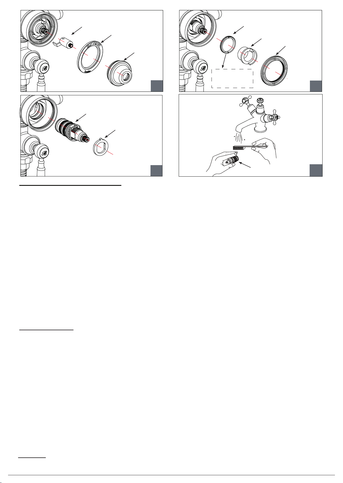
METAL BLOCK
PLASTIC BLOCK
METAL RING
CARTRIDGE
CLAMP NUT
CERAMIC RING
CARTRIDGE
CAP
Use part A to
loosen/tighten the
cartridge clamp nut.
34
CARTRIDGE
LOCATION LUG
CARTRIDGE