AIR-EAGLE®XLT
Analog & Digital 900 MHz RF Receiver
MODEL 441AN/DP-5-0003-120VAC
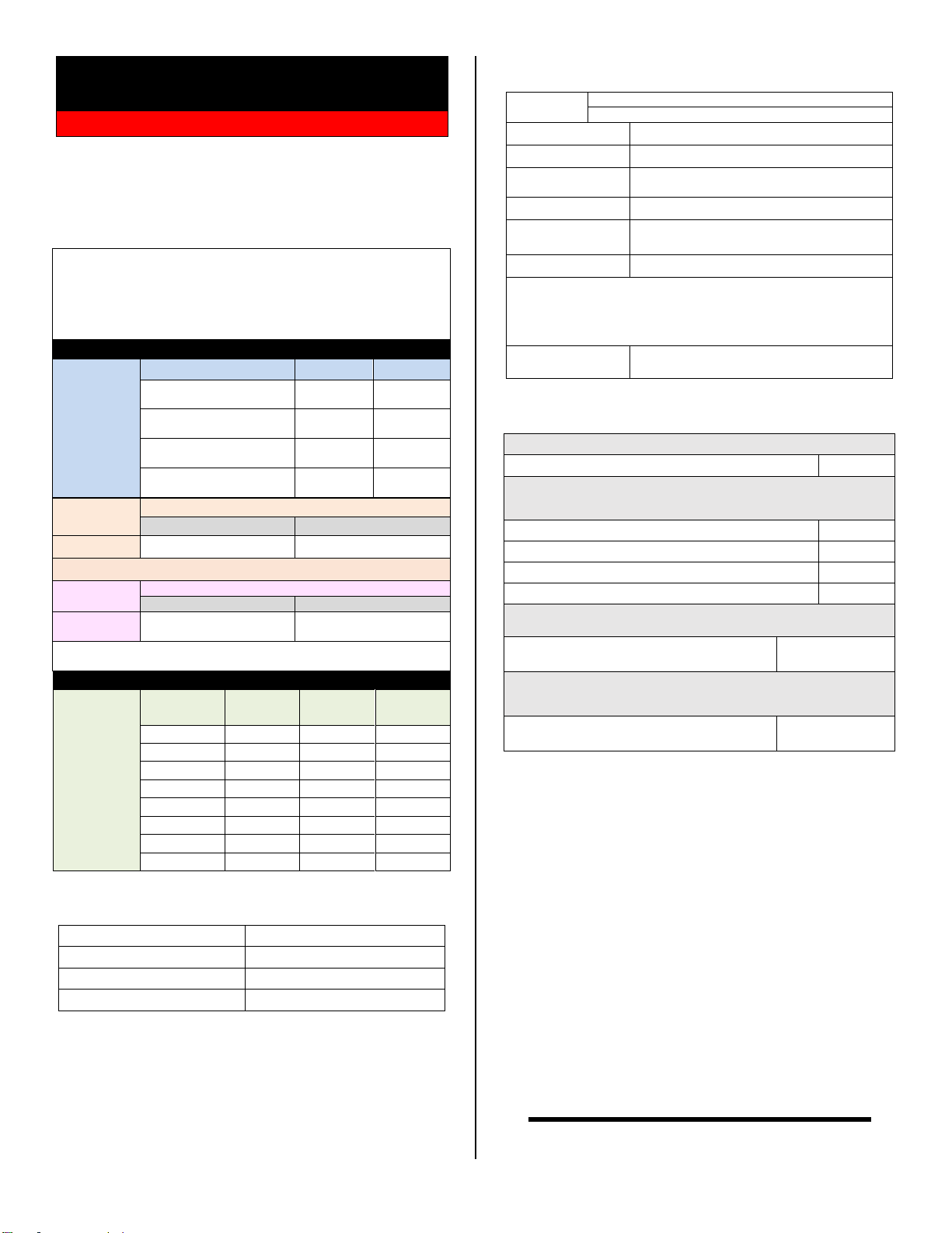
OUTPUT OPTIONS & FREQUENCY SET-UP
This receiver is factory set with an analog output of 0-24mA selected and
to operate onfrequency #1. If you wish to change the default settings,
follow the instructions using the table below:
1) Remove power from unit
2) Remove top cover.
3) Select desired output option and/or frequency using table below.
4) Reattach cover and apply power.
5) Programming is now complete.
0-24mA Output (default)
TER2 Pins 1 and 2
0-20mA Output
TER2 Pins 1 and 2
4-20mA Output
TER2 Pins 1 and 2
Voltage Output
TER2 Pins 1 and 3
Note –SW3 is only to be used if running in “voltage mode”
Analog output at 0% at
power up (default)
Power on with previous
analog setting
NOTE: Analog output must stay at a level for 30 seconds before it is
saved.
One 4-20mA or voltage output (0-5 or 0-10 VDC)
One DPDT2amps @120VAC or 30VDC relay output
100-240 VAC, 16 W, 50/60 Hz fromsupplied
wall adapter
Polycarbonate NEMA 4 (IP66)
900MHz Spread Spectrum
8 Independent Networks
Up to 2500 Feet w/Standard Antenna
Note: Max range figures are estimates, based on free-air terrain with limited sources of
interference. Actual range will vary based on transmitting power, orientation of
transmitter and receiver, height of transmitting antenna, height of receiving antenna,
weather conditions, interference sources in the area, and terrain between receiver and
transmitter, including, but not limited to, indoor and outdoor structures such as walls,
metal objects, trees, buildings, hills, and mountains.
Standard Antenna (Included):
900MHz TNC “Rubber Duck” Antenna
Mobile/Base Antennas –
Used to help achieve max range in both nonline of sight and line of
sight applications. - ContactBWI Eagle for recommendations
900MHz Thru-Hole Mount Mobile Antenna
900MHz Magnet Mount Mobile Antenna
900MHz Omni Directional Base Antenna
900MHz Yagi Directional Base Antenna
High Quality Coax Cables –
Used to connect external high gain antennas to control unit
Flex Coax Cable w/Connectors –Available in
5’,15’,25’,30’,40’,60’,80’,100’ Lengths
49-4000-XX
(XX = # of Feet)
Bulkhead Extensions –
Used to provide an external antenna connection whenmounting
control unit inside another enclosure
TNC Male to TNCBulkhead CableAssembly
- Available in 2’, 4’, 7’ Lengths
49-5004-X-ISO
(X = # of Feet)
LIMITED WARRANTY STATEMENT
BWI Eagle Inc. warrants the Air-Eagle Remote Control System, if properly
used and installed, will be free from defects inmaterial and workmanship
for a period of 1 year after date of purchase. Said warranty to includethe
repair or replacement of defective equipment. This warranty does not
cover damage due to external causes, including accident, problems with
electrical power, usage not in accordance with product instructions,
misuse, neglect, alteration, repair,improperinstallation, or improper
testing. This limited warranty, and any implied warranties that may exist
under state law, apply only to the original purchaser of the equipment, and
last only for as long as such purchaser continues to own the equipment.
This warranty replaces all other warranties, express or implied including,
but not limited to, the implied warranties or merchantability and fitness for
a particular purpose. BWI Eaglemakes no express warranties beyond
thosestated here. BWI disclaims without limitation, implied warranties of
merchantability and fitness for a particular purpose. Some jurisdictions do
not allowthe exclusion of implied warranties so this limitation may not
apply to you. To obtain warranty service, contact BWI Eagle for a return
material authorization. When returning equipment to BWI Eagle, the
customer assumes the risk of damage or loss during shipping and is
responsible for the shipping costs incurred.
DOCUMENT DATE: 09/21/2021 / PRODUCT REV.3


