AIR-EAGLE®XLT
900 MHz RF Receiver
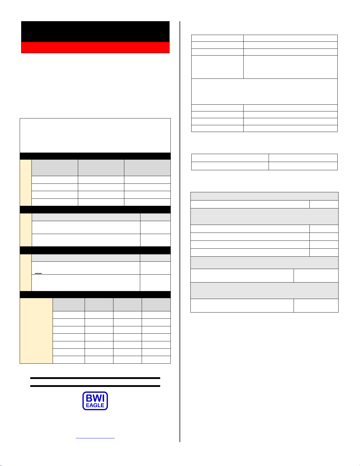
OPTIONS & FREQUENCY SET-UP
The unit is shipped from the factory with all SEL1 switches inthe open
positions. By default, the link-loss shutdown timeis setto .5 seconds;
power must be recycled to reset thesystemfollowing an E-stop event; all
relays respond to either E-stop command; and the unit is operating on
Frequency #1. If you wish to select different options and/or change the
frequency, follow the instructions on the table below.
1) Remove power from unit
2) Remove top cover.
3) Select desired options and/or frequency using table below.
4) Reattach cover and apply power.
5) Programming is now complete.
Link-Loss
Shutdown Time
in Seconds
Powermust be recycled to receiver following any
E-stop event (default)
Relays revert to energized state upon release of E-
stop button and resumption ofcommunication link
Relay Response to E-Stop Event
All four relays de-energize upon E-stopcommand
OR link-loss (default)
Relays 1 & 2 de-energize upon E-stop command;
Relays 3 & 4 de-energize upon link loss
DOCUMENT DATE: 03/06/2020 / PRODUCT REV. 5
105 Bonnie Drive
Butler, PA 16002
(724) 283-4681
Fax (724) 283-5939
www.bwieagle.com
SPDT 5 amp @ 120VAC or 30VDC
Up to 2500 feet when using handheld
transmitter / Up to 2 miles when using
stationary transmitter & external high
gain antennas
Note: Range figures are estimates, based on free-air terrain with limited sources of
interference. Actual range will vary based on transmitting power, orientation of
transmitter and receiver, height of transmitting antenna, height of receiving antenna,
weather conditions, interference sources in the area, and terrain between receiver and
transmitter, including, but not limited to, indoor and outdoor structures such as walls,
metal objects, trees, buildings, hills, and mountains.
902 –928 MHz Spread Spectrum
Eight Independent Network Frequencies
Polycarbonate, NEMA 4, IP66
Standard Antenna (Included):
900MHz TNC “Rubber Duck” Antenna
High Gain Antennas –
Used to help achieve max range in both non line of sight and line
of sight applications. - Contact BWI Eagle for recommendations
900MHz Thru-Hole Mount Omni Directional Antenna
900MHz Magnet Mount Omni Directional Antenna
900MHz Omni Directional Antenna
High Quality Coax Cables –
Used to connect external high gain antennas to control unit
Flex Coax Cable w/Connectors –Available
in 5’,15’,25’,30’,40’,60’,80’,100’ Lengths
49-4000-XX
(XX = # of Feet)
Bulkhead Extensions –
Used to provide an external antenna connection when mounting
control unit inside another enclosure
TNC Male to TNCBulkhead CableAssembly
- Available in 2’, 4’, 7’ Lengths
49-5004-X-ISO
(X = # of Feet)
LIMITED WARRANTY STATEMENT
BWI Eagle Inc. warrants theAir-Eagle Remote ControlSystem, if properly
used and installed, will be free fromdefects in material and workmanship
for a period of 1 year after date of purchase. Said warranty to include the
repair or replacement of defective equipment. This warranty does not
cover damage due to external causes, including accident, problems with
electrical power, usage not in accordance with product instructions,
misuse, neglect, alteration, repair,improperinstallation, or improper
testing. This limited warranty, and any implied warranties that may exist
under state law, apply only to the original purchaser of the equipment, and
last only for as long as such purchaser continues to own the equipment.
This warranty replaces all other warranties, express or implied including,
but not limited to, the implied warranties or merchantability and fitness for
a particular purpose. BWI Eaglemakes no express warranties beyond
thosestated here. BWI disclaims without limitation, implied warranties of
merchantability and fitness for a particular purpose. Some jurisdictions do
not allow the exclusion of implied warranties so this limitation may not
apply to you. To obtain warranty service, contact BWI Eagle for a return
material authorization. When returning equipment to BWI Eagle, the
customer assumes the risk of damage or loss during shipping and is
responsible for the shipping costs incurred.


