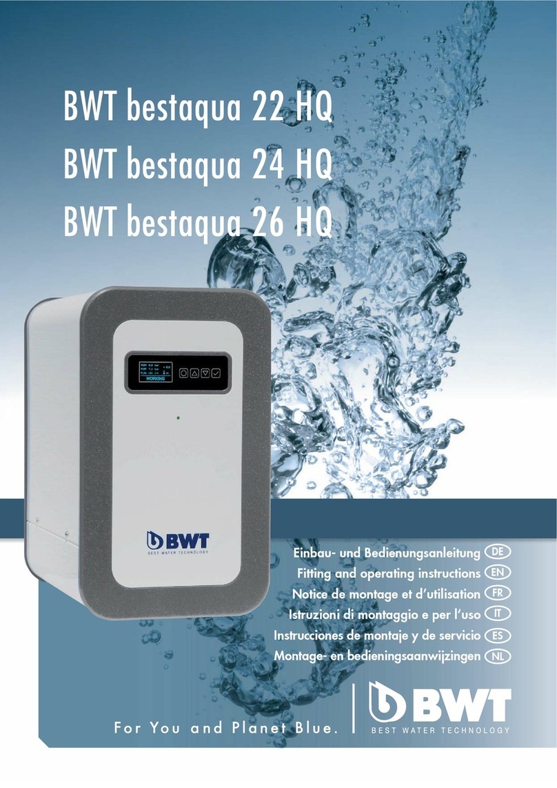
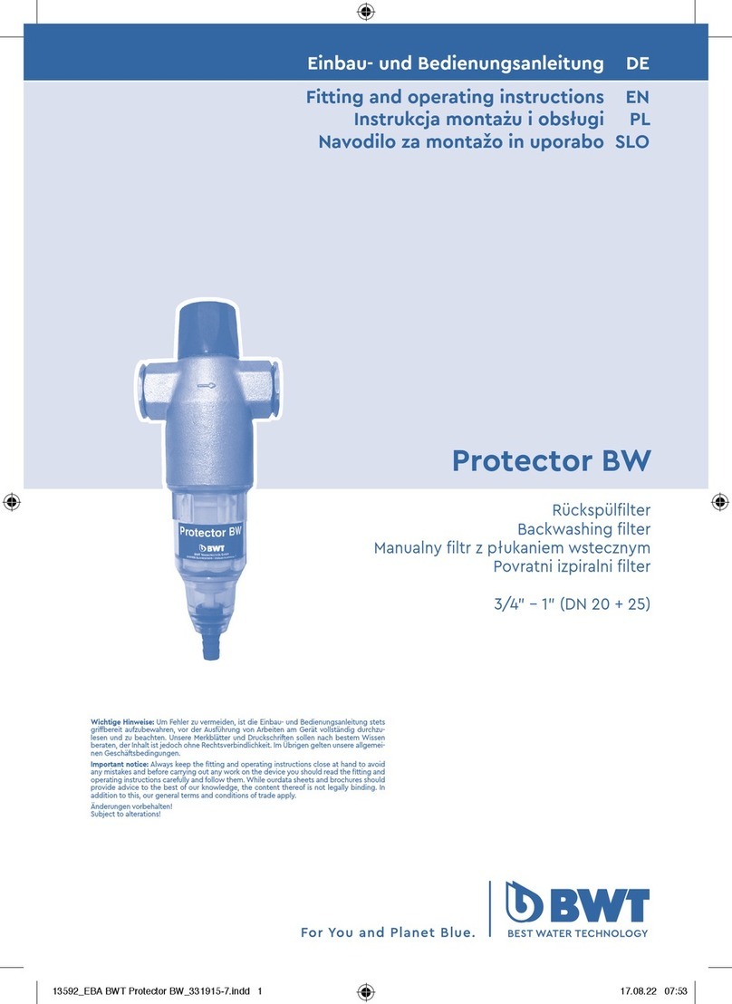
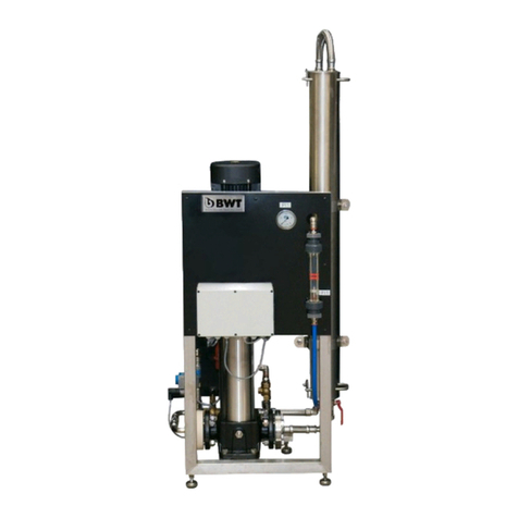
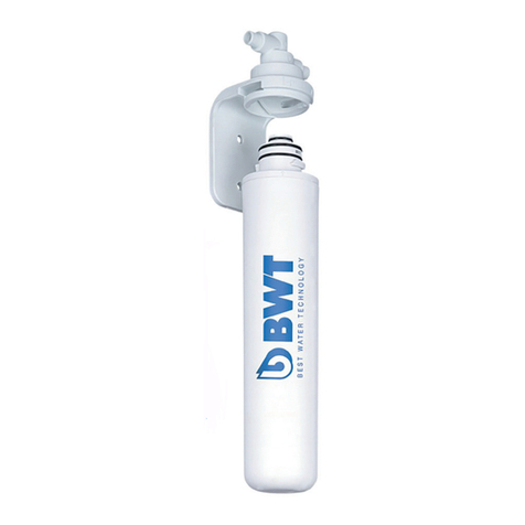
BWT AQA nano User manual

AQA nano
Kalkschutz
Limescale protection
Appareil anti-calcaire
Protezione anticalcare
Protección contra la cal
Antikalktoestel
Einbau- und Bedienungsanleitung DE
Installation and operating manual EN
Notice de montage et d‘utilisation FR
Istruzioni di montaggio e servizio IT
Instrucciones de montaje y funcionamiento ES
Montage- en bedieningshandleiding NL
Effektiver Kalkschutz bis 20°dH und Durchflussleistungen
von bis zu 25 Litern pro Minute
Effective limescale protection up to 20°dH and
flow rates of up to 25 litres per minute
Protection efficace contre les dépôts calcaires jusqu’à
20°dH et pour des débits jusqu’à 25 litres par minute
Reale protezione anticalcare fino a 20°dH e
potenze di erogazione fino a 25 litri al minuto
Protección eficaz contra la cal hasta 20° alemanes de
dureza y prestaciones de flujo de hasta 25 litros por minuto
Een efficiënte bescherming tegen kalkafzettingen tot 20°dH en
voor debieten tot 25 liter per minuut.
Wichtige Hinweise: Um Fehler zu vermeiden, ist die Einbau- und Bedienungsanlei-
tung stets griffbereit aufzubewahren, vor der Ausführung von Arbeiten am Gerät
vollständig durchzulesen und zu beachten. Unsere Merkblätter und Druckschriften
sollen nach bestem Wissen beraten, der Inhalt ist jedoch ohne Rechtsverbindlich-
keit. Im Übrigen gelten unsere allgemeinen Geschäftsbedingungen.
Important notice: Always keep the fitting and operating instructions close at hand
to avoid any mistakes and before carrying out any work on the device you should
read the fitting and operating instructions carefully and follow them. While ourda-
ta sheets and brochures should provide advice to the best of our knowledge, the
content thereof is not legally binding. In addition to this, our general terms and
conditions of trade apply.
Änderungen vorbehalten!
Subject to alterations!

2
NL
ES
IT
FR
EN
Vielen Dank für das Vertrauen, das
Sie uns durch den Kauf eines BWT
Gerätes entgegengebracht haben.
Thank you very much for the con-
fidence that you have shown in us
by purchasing a BWT appliance.
Nous vous remercions de la confi-
ance dont vous nous témoignez
par l’achat d’un appareil BWT.
Vi ringraziamo per la fiducia
accordataci acquistando un’
apparecchiatura BWT.
Muchas gracias po la confianza
depositada en nosotros al comprar
un equipo BWT.
Hartelijk dank voor het vertrouwen
dat u in ons gesteld hebt door uw
aankoop van een BWT-apparaat.
Inhaltsverzeichnis Seite 3
Table of contents Page 10
Table des matières Page 17
Indice Pagina 24
Índice Página 31
Inhoud Pagina 38
DE

3
DE
1. Lieferumfang.......................................................................................................................................................... 5
2. Funktion & Einsatz................................................................................................................................................ 5
3. Einbauvorbedingungen....................................................................................................................................... 5
4. Einbau..................................................................................................................................................................... 6
5. Inbetriebnahme .................................................................................................................................................... 6
6. Betrieb.....................................................................................................................................................................7
7. Wechsel der Kalkschutzeinheit............................................................................................................................7
8. Inspektion ...............................................................................................................................................................7
9. Betreiberpflichten .................................................................................................................................................7
10. Gewährleistung................................................................................................................................................... 8
11. Garantie................................................................................................................................................................. 8
12. Technische Daten................................................................................................................................................ 8
13. Technische Zeichnung........................................................................................................................................ 9
Inhaltsverzeichnis

4
DE
Bild 1 Bild 2 Bild 3 Bild 4
Bild 5 Bild 6 Bild 7 Bild 8
Bild 9 Bild 10 Bild 11 Bild 12
Bild 13 Bild 14 Bild 15 Bild 16
Bild 17 Bild 18 Bild 19 Bild 20

5
DE
Werter Kunde,
vielen Dank, dass Sie sich für ein BWT Kalkschutz-
gerät der neuesten Generation entschieden haben.
Mit AQA nano steigen Sie preiswert in die Welt der
BWT Nanokristall-Technologie ein und sichern sich
und Ihrer Familie gleichzeitig einzigartige Vorteile:
• BWT Komfort: AQA nano ist bedienungsfrei,
die Elektronik erinnert Sie zuverlässig an die
jährlich vorgeschriebene Wartung.
• BWT Sicherheit: Schutz vor Kalkinfarkt,
verstopften Leitungen und unnötigem
Hygienerisiko durch Ablagerungen bis 20°
Gesamthärte.
• BWT Trinkwassergarantie: Genießen Sie
weiterhin alle wertvollen und lebenswichtigen
Mineralstoffe wie Kalzium und Magnesium. Ihr
Trinkwasser bleibt wie es ist!
• BWT Servicegarantie: Lehnen Sie sich zurück
und genießen Sie das gute Gefühl einen
kompetenten Partner an der Seite zu haben.
Verlassen Sie sich auf das Aqua Service
Garantie- und Leistungspaket des euro-
päischen Marktführers.
Hinweis:
Bewahren Sie die Einbau- und Bedienungsanlei-
tung stets griffbereit auf, um Fehler zu vermeiden.
Vor der Ausführung von Arbeiten ist die Einbau- und
Bedienungsanleitung vollständig durchzulesen und
zu beachten.
1. Lieferumfang
AQA nano Kalkschutz
AQA nano wird komplett mit neu entwickelter Kalk-
schutzeinheit zur Nanokristall-Bildung, modernster
integrierter Steuereinheit und Anschlussverschrau-
bungen geliefert.
Für eine erleichterte Wartung empfehlen wir vor
und nach dem AQA nano Kalkschutzgerät den op-
tional erhältlichen BWT Trinkwasserkugelhahn als
robuste und zuverlässige Wartungsabsperrung ein-
zubauen.
2. Funktion & Einsatz
Kalkschutz
AQA nano arbeitet nach dem Prinzip der Nanokris-
tall-Bildung. Die integrierte Kalkschutzeinheit be-
steht aus einer dreidimensionalen Elektrode. Durch
definierte Strom-/Spannungsimpulse kommt es zu
einer lokalen Verschiebung des Kalk-Kohlensäure-
Gleichgewichts im Wasser, wodurch sog. Nano-
kristalle gebildet werden. Aufgrund ihrer geringen
Größe tragen die Nanokristalle eine elektrische
Ladung, welche ein Zusammenwachsen verhindert.
Die Gesamtheit der Nanokristalle ist in der Lage,
den Kalk im Wasser aufzufangen und dadurch Ab-
lagerungen in Rohrleitungen und Boilern zu vermin-
dern. Das Trinkwasser bleibt wie es ist.
Einsatzzweck
AQA nano wird zum Kalkschutz und somit zur Ver-
minderung von Kalkausfall in Trinkwasser führenden
Rohrleitungen bis 20 °dH und in den nachgeschal-
teten, geschlossenen Warmwasserbereitern bis
80 °C (Oberflächentemperatur) eingesetzt.
Die Aufbereitung anderer Medien als Trinkwas-
ser für den menschlichen Gebrauch und die Ver-
wendung außerhalb der Durchflussgrenzen von
25 l/min ist nicht vorgesehen und führt zum Verlust
aller Haftungsansprüche an den Hersteller. Einbau-
vorbedingungen, Verwendungsgrenzen, örtliche
Installationsvorschriften, allgemeine Richtlinien
(z.B. DIN, VDE, DVGW, ÖVGW, SVGW, WVU, EVU,
..), allgemeine Hygienebedingungen und techni-
sche Daten, sind zu beachten.
Der Einbauort muss frostsicher sein und der Schutz
des Gerätes vor Wärmequellen über 40 °C und
Chemikalien aller Art muss gewährleistet sein. Für
die Zusammensetzung von Trinkwasser gilt die EU
Richtlinie 98/83. Ebenso gelten die WHO Trinkwas-
serstandards sowie die Trinkwasserverordnung.
3. Einbauvorbedingungen
Örtliche Installationsvorschriften, allgemeine Richt-
linien, allgemeine Hygienebedingungen und tech-
nische Daten beachten.
Der Einbauort muss frostsicher sein und den Schutz
der Anlage vor Chemikalien, Farbstoffen, Lösungs-
mitteln, Dämpfen und Umwelteinflüssen gewähr-
leisten. Die Umgebungstemperatur darf 40 °C nicht
überschreiten. Das Gerät vor direkter Sonnenein-
strahlung und UV-Licht schützen.
Der Bereich vom Wasserzähler bis 1 m nach dem
AQA nano Gerät ist korrosionssicher auszuführen.
Wir empfehlen den Einsatz eines HydroMODUL
Hauswasserverteilers, der darüber hinaus eine
schnelle & kostengünstige Montage ermöglicht.
Verwenden Sie das HM-Einbauset für die Integrati-
on von AQA nano in eine bestehende HydroModul
Basisinstallation.
6
DE
Dem Gerät ist zum Schutz vor Fremdpartikeln zwin-
gend ein DIN/DVGW (bzw. ÖVGW) geprüfter Trink-
wasserfilter vorzuschalten.
Zum Schutz der gesamten Installation und der An-
lage sollte bei einem Netzdruck größer 4 bar ein
Druckminderer vorgeschaltet werden.
Für die Funktionskontrolle des AQA nano ist eine
Prüfstrecke erforderlich. Diese kann einfach mit
2 HM-Verlängerungen (= 244 mm) im HydroMODUL
System realisiert werden.
4. Einbau
Gehen Sie sicher, dass am Einbauort eine Schutz-
steckdose vorhanden ist. Die Länge des Anschluss-
kabels des Gerätes beträgt 1 Meter.
I. Auspacken
Nehmen Sie das Gerät aus der Verpackung und
prüfen Sie die Lieferung auf Vollständigkeit und auf
etwaige Transportschäden.
II. Durchflussrichtung
Beachten Sie bereits vor der Montage die ge-
wünschte Durchflussrichtung. Das Gerät wird stan-
dardmäßig mit einer Durchflussrichtung "von links
nach rechts" ausgeliefert.
Sollte es nötig sein die Durchflussrichtung zu
ändern, so gehen sie wie folgt vor:
a. Die Geräteverkleidung, nach dem Lösen der
beiden Halteschrauben (Rändelschrauben) an
der Geräteseite, abnehmen (siehe Bild 1 und 2).
b. Legen Sie das Gerät mit der Rückseite nach
oben auf eine weiche Unterlage (siehe Bild 3).
c. Lösen Sie die Montagehalterung und nehmen
Sie diese ab (siehe Bild 4).
d. Drücken Sie zum Lösen des Anschlussteiles
den Sicherungsring an den beiden Laschen
zusammen und ziehen Sie ihn in Richtung des
Anschluss-Stückes (siehe Bild 5).
e. Drehen Sie das Anschluss-Stück um 45°
gegen den Uhrzeiger und nehmen Sie es ab
(siehe Bild 6).
f. Wenden Sie das Basisstück entsprechend der
Durchflussrichtung verbinden Sie es wieder
mit dem Gerät (siehe Bild 7, 8, 9).
g. Achten Sie dabei auf die Durchflussrichtungs-
pfeile und auf das Einrasten des Sicherungs-
ringes. Sofern AQA nano in eine senkrechte
Leitung eingebaut werden soll, drehen Sie
den Anschlussteil nur um 45°. Danach wird
dieser wieder aufgesetzt und gesichert.
h. Montieren Sie danach den Befestigungsbügel
wieder in seiner ursprünglichen Position.
III. Verbindung mit der Wasserleitung
Verbinden Sie das Gerät mithilfe der im Lieferum-
fang enthaltenen Anschlussverschraubungen mit
der Rohrleitung, sowie mit dem mitgelieferten Be-
festigungswinkel, den Schrauben und den Dübeln
an der Wand.
Der Wandabstand der Rohrachse kann bei
AQA nano zwischen 80 mm und 100 mm liegen. Der
minimale Bodenabstand der Rohrachse bzw. des
Montagepunktes in senkrechten Leitungen beträgt
500 mm.
Nach der Vorbereitung der Rohrleitung die Wand-
halterung befestigen und das Gerät auf die Wand-
halterung aufsetzen.
Die beiden Schrauben verbinden Ihr AQA nano
Kalkschutzgerät mit der Wandhalterung (siehe Bild
10 und 11).
5. Inbetriebnahme
Öffnen Sie nach der Installation bzw. nach dem
Wechsel der Kalkschutzeinheit die Absperrarmatur
(z.B. BWTTrinkwasserkugelhahn) vor der AQA nano
Kalkschutzanlage und setzen Sie das Gerät unter
Druck. Kontrollieren Sie anschließend alle Anschlüs-
se auf ihre Dichtheit.
Wichtig!
AQA nano und die integrierte Kalkschutzeinheit
werden aus hygienischen Gründen trocken ausge-
liefert. Aus diesem Grund empfehlen wir, das Ge-
rät bei der Inbetriebnahme durch das Öffnen eines
Entleerungshahnes nach der Anlage, für ca. drei
Minuten gründlich zu spülen. Auf diese Weise wer-
den auch Späne und andere Verunreinigungen, die
bei der Installation eingebracht wurden, ausge-
spült.
Stecken Sie das Netzkabel danach in die vorgesehe-
ne Schutzkontaktsteckdose und überprüfen Sie die
Funktion der beiden grünen Kontroll-LEDs im Sicht-
fenster. Beide Kontrolllampen müssen leuchten. Bei
Wasserentnahme beginnt die obere Kontroll-LED
im Zwei-Sekunden-Takt zu blinken. Sollte dieses Si-
gnal nicht angezeigt werden, so überprüfen Sie die
Durchflussrichtung, die Stromversorgung und die
Kabelverbindungen.
Das Gerät ist nun einsatzbereit!

7
DE
6. Betrieb
AQA nano zeigt alle Betriebszustände durch die
zwei Kontroll-LEDs im Sichtfenster an (siehe Bild 12).
Bei Wasserentnahme blinkt die obere Kontrolllam-
pe im Zwei-Sekunden-Takt. Wenn die Kontroll-LED
„IN OPERATION” erlischt, so ist die Kalkschutzein-
heit, wie unter Punkt 7 beschrieben, zu wechseln.
Wenn die Kontrolllampe „POWER” erlischt, ist ent-
weder die Stromversorgung gestört oder es liegt
eine schwerwiegende Beschädigung des Gerätes
vor. Blinkt die Kontrolllampe „POWER” bei Wasse-
rentnahme nicht, so erfolgt die Wasserentnahme
nicht durch das Gerät oder es liegt ein Gerätefehler
vor. Wenden Sie sich in diesem Fall an Ihren Installa-
teur oder Ihren BWT Fachberater.
7. Wechsel der Kalkschutzeinheit
Sobald die Kontroll-LED „IN OPERATION” erlischt,
muss die Kalkschutzeinheit gewechselt werden.
I. Sperren Sie dazu die Wasserleitung vor und
nach AQA nano ab und lösen Sie die Halte-
schrauben seitlich am Gerät (siehe Bild 13).
II. Nehmen Sie die Geräteverkleidung ab.
III. Durch das Öffnen der schwarzen Ablass-
Schraube an der Unterseite des Klarsicht-
zylinders können Sie die Druckentlastung
durchführen (siehe Bild 14).
IV. Schrauben Sie den Klarsichtzylinder danach
ohne Werkzeug ab (siehe Bild 15).
V. Ziehen Sie nun die Kalkschutzeinheit ab
(siehe Bild 16). Sie können die Kalkschutz-
einheit bedenkenlos dem Hausmüll oder dem
Kunststoffrecycling zuführen.
VI. Öffnen Sie die Schutzhülle der neuen
Kalkschutzeinheit und nehmen Sie diese unter
Verwendung der beigelegten Hygienehand-
schuhe aus der Verpackung (siehe Bild 17).
VII. Setzen Sie die Kalkschutzeinheit nun an den
beiden Titanelektroden so an, dass die
Spitzen der Elektroden in die Kalkschutz-
einheit ragen (siehe Bild 18).
VIII. Schieben Sie die Kalkschutzeinheit nun bis
zum Einrasten über die Elektroden (siehe Bild
19).
IX. Schrauben Sie jetzt den Klarsichtzylinder
wieder ohne Werkzeug fest.
X. Bestätigen Sie den Tausch der Kalkschutzein-
heit nun, indem Sie die Taste "RESET" für ca.
drei Sekunden gedrückt halten (siehe Bild 20).
Die grüne Kontrollleuchte "IN OPERATION"
leuchtet nun wieder auf.
XI. Prüfen Sie abschließend alle Kabelver-
bindungen auf ihren festen Sitz und montieren
Sie die Geräteverkleidung mit den beiden
Halteschrauben.
8. Inspektion
Für die optimale Hygienesicherheit, eine einwand-
freie Funktion und eine lange Gerätelebensdauer
empfehlen wir Ihnen eine regelmäßige Sichtkont-
rolle des Geräts (mind. 1 x proWoche) und die Über-
prüfung des Betriebszustandes (LED-Leuchten). Die
professionelle Wartung/Servicierung durch Ihren
Fachinstallateur oder unseren BWT Werkskunden-
dienst schafft zudem höchste Sicherheit.
9. Betreiberpflichten
Sie haben ein langlebiges und servicefreundliches
Produkt gekauft. Jede technische Anlage benötigt
jedoch einen regelmäßigen Service, um die ein-
wandfreie Funktion zu erhalten. Voraussetzung für
die Funktion und etwaige Gewährleistungs- und
Garantieansprüche sind die Einhaltung der in dieser
Bedienungsanleitung angeführten Vorgaben.
Diese betreffen insbesondere:
Sichern Sie sich Ihre Ansprüche und lassen Sie
sämtliche Service- und Wartungsarbeiten, sowie
den Austausch von Verschleiß- bzw. Ersatzteilen
ausschließlich durch Fachpersonal (gerätekundige
Installationsfirma bzw. BWT Werkskundendienst)
ausführen. Vertrauen Sie auf original BWT Ersatz-
und Verschleißteile – diese garantieren Ihnen Zu-
verlässigkeit für viele Jahre!
Wir empfehlen, einen Wartungsvertrag mit Ihrem
Installateur oder dem BWT Werkskundendienst ab-
zuschließen.
POWER IN OPERATION
Stand-By (bei-
de LEDsleuchten)
Stand-By, Kalkschutzeinheit
tauschen
Wasserentnahme
(POWER blinkt) (())
Wasserentnahme, Kalk-
schutzeinheit tauschen (())
Keine Stromversorgung
oder elektrischer Defekt

8
DE
10. Gewährleistung
Im Störfall während der Gewährleistungszeit wen-
den Sie sich bitte unter Nennung des Gerätetyps
(siehe technische Daten bzw. Typenschild des Gerä-
tes) an Ihren Vertragspartner, die Installationsfirma
oder an den BWTWerkskundendienst. Es gelten die
nationalen gesetzlichen Gewährleistungsbestim-
mungen in der jeweils neuesten Fassung.
Qualifiziertes Personal:
Nur Fachpersonal darf das Produkt installieren, in
Betrieb nehmen und Instand halten. Die Bedienung
und der Gebrauch hat durch unterwiesene Perso-
nen zu erfolgen.
Unterwiesene Person:
Wurde in einer Unterweisung und durch die Infor-
mationen aus dieser Anleitung über die ihr über-
tragenen Aufgaben und mögliche Gefahren bei
unsachgemäßem Verhalten unterrichtet.
Fachpersonal:
Ist aufgrund seiner fachlichen Ausbildung, Kenntnis-
se und Erfahrung sowie Kenntnis der einschlägigen
Bestimmungen in der Lage, das Produkt zu instal-
lieren, in Betrieb zu nehmen und Instand zu halten.
11. Garantie
Beim Kauf von AQA nano sind die Leistungen des
Aqua Service basic Garantiepakets (2 Jahre BWT
Werksgarantie) bereits inbegriffen. Voraussetzung
hierfür ist der Bezug des Geräts über den Fachhan-
del und die Installation durch einen autorisierten
Installateur.
12. Technische Daten
AQA nano
Anschlussnennweite DN 25
Anschlussgewinde Außengewinde 1"
Kalkschutzleistung bis max. 20° dH m
3
/h max. 1,5
l/min. max. 25
l/min. min. 0,6
Kalkschutzkapazität m
3
max. 110 ± 10*
Monate max. 12
Betriebsdruck PN bar 16
Temperatur Wasserzulauf max. °C 30
Temperatur Umgebung max. °C 40
Temperatur Boiler °C 80
Geräteabmessungen und Anschlussmaße:
Breite x Höhe mm 300 × 710
Einbaulänge (mit Verschraubungen) mm 234
Abstand: Wand Rohrmitte mm 80 bis 100
Gewicht kg ca. 11
Kabellänge mm 1000
Netzanschluss Volt/Hertz 230/50, 110/60 **
Elektrische Anschlussleistung Watt 5,5
Leistung Standby-Betrieb Watt 1,8
Energieverbrauch pro m
3
Wasser kWh 0,018
Schutzart IP 54
* je nach Wasserqualität ** länderspezifisch

9
DE
13. Technische Zeichnung
AQA nano
Durchflussrichtung links nach rechts
AQA nano
Durchflussrichtung rechts nach links

10
EN
1. Scope of delivery..................................................................................................................................................12
2. Function & Use.....................................................................................................................................................12
3. Pre-requisites for fitting .....................................................................................................................................12
4. Fitting ....................................................................................................................................................................13
5. Start-up..................................................................................................................................................................13
6. Operation..............................................................................................................................................................13
7. Changing the limescale protection unit..........................................................................................................14
8. Inspection .............................................................................................................................................................14
9. Operator duties....................................................................................................................................................14
10. Warranty..............................................................................................................................................................14
11. Technical Data .....................................................................................................................................................15
12. Technical Drawing..............................................................................................................................................16
Table of contents

11
EN
Fig. 1 Fig. 2 Fig. 3 Fig. 4
Fig. 5 Fig. 6 Fig. 7 Fig. 8
Fig. 9 Fig. 10 Fig. 11 Fig. 12
Fig. 13 Fig. 14 Fig. 15 Fig. 16
Fig. 17 Fig. 18 Fig. 19 Fig. 20

12
EN
Dear Customer,
Thank you for purchasing the latest generation
BWT limescale protection device. With the AQA
nano you are getting value for money and entering
into the world of the BWT nano-crystal technology
and at the same time giving you and your family
unique benefits:
• BWT Comfort: AQA nano is unmanned and
you can rely on the electronics to remind you of
the annual service required.
• BWT Security: Protection against extreme
calcification, blocked pipes and unnecessary
hygiene risks from deposits up to 20° total
hardness.
• BWT Drinking water guarantee: You will still
enjoy all the valuable and essential mineral
nutrients like calcium and magnesium. Your
drinking water stays as it is!
• BWT Service guarantee: Sit back and enjoy
the good feeling of having a competent partner
at your side. You can rely on the Aqua Service
guarantee and service package of the
European market leader.
Note:
Always keep the fitting and operating instructions
close at hand to avoid any mistakes and before car-
rying out any work, read the fitting and operating
instructions carefully and follow them.
1. Scope of delivery
AQA nano limescale protection
AQA nano comes complete with the recently de-
veloped limescale protection unit for forming na-
no-crystals, the latest integrated control unit and
screw connections.
To make maintenance easier, we would recom-
mend
before and after the AQA nano limescale protection
device, fitting a robust and reliable maintenance
shut-off device.
2. Function & Use
Limescale protection
AQA nano works on the principle of nano-crystal
formation. The integrated limescale protection unit
consists of a three-dimensional electrode. Defined
current/voltage pulses cause a local displacement
of the limescale carbonic acid balance in the wa-
ter, causing so-called nanocrystals to be formed.
Because of their small size, the nano-crystals carry
an electrical charge that prevents adherence. The
nano-crystals as a whole are able to absorb the li-
mescale in the water and thus prevent deposits in
pipe work and boilers. The drinking water remains
unaffected.
Application
AQA nano is used for limescale protection and
thus for the prevention of limescale stains in pipes
carrying drinking water up to 20 °dH and in the
downstream, closed water heaters up to 80 °C
(surface temperature). The processing of other
media as drinking water for human consumption
and use outside the flow limits of 25 l/min is not
intended and shall lead to the loss of any liability
claims against the manufacturer. Any prerequisites
for fitting, limits of use, local installation regulations,
general guidelines (e.g. DIN, VDE, DVGW, ÖVGW,
SVGW, WVU, EVU,…), general hygiene require-
ments and technical data shall be adhered to.
The installation area must be frost-proof and pro-
tection of the device against heat sources over
40 °C and chemicals of any type must be guaran-
teed. In terms of the composition of drinking water,
the EU Directive 98/83 shall apply. Likewise, the
WHO Drinking Water Standards and the Drinking
Water Ordinance shall apply.
3. Pre-requisites for fitting
Local installation regulations, general guidelines,
general hygiene requirements and technical data
shall be followed.
The installation area must be frost-proof and gua-
rantee the protection of the system against che-
micals, dyes, solvents, vapours and environmental
influences. The ambient temperature must not ex-
ceed 40 °C. Protect the device from direct sunlight
and ultra-violet light.
The area from the water meter to 1 m after the
AQA nano device shall have a corrosionresistant
finish.
To protect the device from foreign particles, it is
essential to add a DIN/DVGW (or ÖVGW) tested
drinking water filter.
To protect the whole installation and the system, a
pressure reducer should be added at a mains pres-
sure greater than 4 bar.

13
EN
A testing line is required for the function check of
the AQA nano. This can be done simply with 2 HM-
extensions (= 244 mm) in the HydroMODUL system.
4. Fitting
Make sure that there is a sheltered socket in the in-
stallation area. The length of the connection cable
of the device is 1 metre.
I. Unpacking the device
Remove the device from its packaging and check
the delivery to see that everything is there and for
any damage caused during transport.
II. Flow direction
Please note the desired flow direction prior to as-
sembly. The device comes as standard with a flow
direction "from left to right". If you need to change
the flow direction, then proceed as follows:
a. Remove the device cladding after releasing
the two locking screws (knurled screws) on
the side of the device (see Fig. 1 und 2).
b. Set the device down with its back facing up
on a soft base (see Fig. 3).
c. Release the assembly bracket and remove it
(see Fig. 4).
d. To release the connector, press the circlip on
both flaps together and pull it in the
direction of the connection (see Fig. 5).
e. Turn the connection 45° anticlockwise and
remove it (see Fig. 6).
f. Turn the base in the flow direction and
re-connect it to the device (see Fig. 7, 8, 9).
g. In so doing, please note the flow direction
arrows and make sure the circlip clicks in. If
the AQA nano is to be fitted in a vertical pipe,
only turn the connector 45°. Then this is
fitted again and secured.
h. Then fit the support bracket back to its
original position.
III. Connecting to the water pipe
Connect the device using the screw connection
supplied to the pipe, and using the fastening bra-
cket, screws and dowels supplied, to the wall. The
projection of the tubular axle in AQA nano may be
between 80 mm and 100 mm.
The minimum ground clearance of the tubular axle
or the assembly point in vertical pipes is 500 mm.
After preparing the pipe, fit the wall bracket and
set the device on the wall bracket.
The two screws connect your AQA nano limescale
protection device to the wall bracket (see Fig. 10
and 11).
5. Start-up
After the installation or after changing the limesca-
le protection unit, open the shut-off valve in front
of the AQA nano limescale protection system and
pressurize the device. Then check that all connec-
tions are properly sealed.
Important!
AQA nano and the integrated limescale protection
unit are supplied dry for hygienic reasons. For this
reason, we recommend thoroughly rinsing the de-
vice on start-up by opening a drain valve for ap-
prox. three minutes. This also allows any shavings
and other impurities introduced on installation to
be rinsed out.
Then put the mains cable into the protective con-
tact socket provided and check that the two green
indicator LEDs are working in the inspection win-
dow. Both indicator lamps must light up. When
water is removed, the upper indicator LED starts
to flash every two seconds. If this signal is not dis-
played, then check the flow direction, the power
supply and the cable connections.
The device is now ready for use!
6. Operation
AQA nano displays all operating conditions through
the two indicator LEDs in the inspection window
(see Fig. 12).
When water is removed, the upper indicator lamp
flashes every two seconds. If the indicator LED
“IN OPERATION” goes out, then the limescale pro-
tection unit, as described in Item 7, must be chan-
ged. If the indicator lamp “POWER” goes out, there
is either a fault in the power supply or the device
has been seriously damaged. If the indicator lamp
“POWER” does not flash when water is removed,
then the water is not removed by the device or the-
re is a fault in the device. In this case, please con-
tact your fitter or your BWT technical advisor.

14
EN
7.
Changing the limescale protection
unit
As soon as the indicator LED “IN OPERATION” goes
out, the limescale protection unit must be changed.
I. Isolate the water pipe before and after
AQA nano and release the locking screws at
the side of the device (see Fig. 13).
II. Remove the device cladding.
III. By opening the black drain screw at the
bottom of the transparent cylinder, you can
carry out the pressure discharge (see Fig. 14).
IV. Unscrew the transparent cylinder then
manually (see Fig. 15).
V. Now detach the limescale protection unit (see
Fig. 16). You can, without any hesitation, put
the limescale protection unit in the domestic
waste or send it to be recycled.
VI. Open the protective covering of the new
limescale protection unit and remove it from
the packaging using the hygiene gloves
supplied (see Fig. 17).
VII.
Now set the limescale protection unit on the
two titanium electrodes in such a way that the
points of the electrodes stick into the limescale
protection unit (see Fig. 18).
VIII. Now push the limescale protection unit until it
clicks over the electrodes (see Fig. 19).
IX. Now tighten the transparent cylinder again
manually.
X. Now confirm that the limescale protection unit
has been changed, by holding the "RESET"
key for around three seconds (see Fig. 20).
The green indicator light "IN OPERATION"
now lights up again.
XI. Finally check that all cable connections are
tight and fit the device cladding using
the two locking screws.
8. Inspection
To guarantee the best level of hygiene safety, effici-
ent working and long life for the device, we would
recommend you carry out a regular visual check of
the device (at least once a week) and check the
operating status (LED lights).
Professional maintenance / servicing by your ex-
pert fitter or our BWT customer service also provi-
de the highest safety levels.
9. Operator duties
Although you have purchased a durable and easy
to maintain product, every technical system requi-
res regular service to guarantee its correct opera-
tion. A precondition for the operation and any war-
ranty and guarantee claims is the compliance with
the specifications listed in these operating instruc-
tions. These specifications concern in particular:
- normal use of AQA nano
- the operation within the operation limits (s.
technical data)
- correct fitting by the approved specialist
company
- Regular tests being carried out
- Service- and maintenance work being carried
out by your specialist fitter or the BWT custo-
mer service
Protect your rights and have all the service and
maintenance work, and the replacement of spare
and wear parts carried out solely by specialist per-
sonnel (installation company familiar with the de-
vice or BWT customer service). Make sure you use
original BWT spare and wear parts – these will gua-
rantee you reliability for many years! We would re-
commend entering into a service agreement with
your fitter or the BWT customer service.
10. Warranty
In the case of a breakdown during the warranty
period, please contact your trade partner giving
the device type (see technical data or name plate
on the device), the installation company or BWT’s
customer service. The national statutory warranty
provisions shall apply as amended.
Qualified staff:
The product may only be installed, commissioned
and serviced by skilled personnel.
Only trained persons are allowed to operate and
use it.
POWER IN OPERATION
Stand- By
(both LEDs light up)
Stand-By, Replace lime-
scale protection unit
Water removal
(POWER flashes) (())
Water removal, remove
limescale protection unit (())
No power supply or elec-
trical fault

15
EN
Trained person:
Has received instruction and studied the informati-
on in this document concerning the tasks entrusted
to him/her, and the possible risks in the event of
inappropriate behaviour.
Skilled personnel:
Based on the professional training received, know-
ledge and experience, and knowledge of the
relevant definitions,isqualifiedtoinstallthe product,
to commission and to service it.
11. Technical Data
AQA nano
Connection nominal diameter DN 25
Connection thread outside thread 1"
Limescale protection up to max. 20°dH m
3
/h max. 1.5
l/min. max. 25
l/min. min. 0.6
Limescale protection capacity m
3
max. 110 ± 10*
months max. 12
Operating pressure PN bar 16
Temperature water inflow max. °C 30
Temperature environment max. °C 40
Temperature boiler max. °C 80
Dimensions of device & connection dimensions:
Width x height mm 300 × 710
Fitting length (with screw connections) mm 234
Clearance: Wall middle of pipe mm 80 to 100
Weight kg ca. 11
Cable length mm 1000
Mains connection Volt/Hertz 230/50, 110/60 **
Electrical connected rating Watt 5.5
Capacity stand-by operation Watt 1.8
Energy consumption per m
3
water kWh 0.018
Type of protection IP 54
* depending on water quality ** country-specific

16
EN
12. Technical Drawing
AQA nano
Flow direction left to right
AQA nano
Flow direction right to left

17
FR
1. Matérial livré..........................................................................................................................................................19
2. Fonctionnement et utilisation...........................................................................................................................19
3. Conditions des montage....................................................................................................................................19
4. Montage ...............................................................................................................................................................20
5. Mise en service....................................................................................................................................................20
6. Fonctionnement .................................................................................................................................................20
7. Remplacement de l'unité anticalcaire .............................................................................................................21
8. Inspection .............................................................................................................................................................21
9. Obligations de l'utilisateur.................................................................................................................................21
10. Garantie..............................................................................................................................................................22
11. Données techniques..........................................................................................................................................22
12. Schémas techniques......................................................................................................................................... 23
Table des matières

18
FR
Ill. 1 Ill. 2 Ill. 3 Ill. 4
Ill. 5 Ill. 6 Ill. 7 Ill. 8
Ill. 9 Ill. 19 Ill. 11 Ill. 12
Ill. 12 Ill. 14 Ill. 15 Ill. 16
Ill. 17 Ill. 18 Ill. 19 Ill. 20

19
FR
Cher client,
Merci d’avoir acheté un appareil anti-calcaire BWT
de la dernière génération. Avec AQA nano, vous dé-
couvrirez à un prix avantageux la technologie des
nanocristaux BWT et vous et votre famille bénéfi-
cierez en même temps d’avantages exclusifs:
• Confort BWT:
AQA nano est simple d’utilisation,
le système électronique vous signalera chaque
année de façon fiable qu’il est temps de
procéder à la maintenance.
• Sécurité BWT: Protège contre le calcaire, les
conduites bouchées et les problèmes
d’hygiène inutiles causés par les dépôts
jusqu’à un titre hydrotimétrique total de 20°.
• Garantie eau potable BWT: Continuez à
profiter de toutes les substances minérales
précieuses et vitales comme le calcium et le
magnésium. Votre eau potable restera de
qualité!
• Garantie de service BWT: Installez-vous
confortablement et profitez de la sensation
agréable d’avoir un partenaire compétent à
vos côtés. Vous pouvez compter sur le
package prestations et garantie Aqua Service
du leader européen.
Remarque:
Conservez toujours à portée de main la notice de
montage et d’utilisation afin d’éviter toute erreur.
Veuillez la lire intégralement et la respecter avant
d’utiliser l’appareil.
1. Matériel livré
Appareil anti-calcaire AQA nano
AQA nano est livré complet, avec une unité anti-cal-
caire nouvellement mise au point pour la formation
de nanocristaux, une unité de commande intégrée
très moderne et des raccords.
Pour faciliter la maintenance, nous recomman-
dons d’installer en amont et en aval de l’appareil
anticalcaire AQA nano un robinet d’eau potable
à boisseau sphérique BWT, disponible en option,
comme dispositif de coupure solide et fiable pour
la maintenance.
2. Fonctionnement et utilisation
Protection contre les dépôts calcaires
Le fonctionnement du système AQA nano est
basé sur la formation de nanocristaux. L’unité anti-
calcaire intégrée se compose d’une électrode tri-
dimensionnelle. Des impulsions de tension et de
courant déterminées provoquent un déplacement
local de l’équilibre calco-carbonique dans l’eau, ce
qui entraîne la formation de nanocristaux. En raison
de leur taille minuscule, ceux-ci portent une char-
ge électrique qui les empêche de se regrouper.
L’ensemble des nanocristaux est capable de captu-
rer le calcaire dans l’eau permettant ainsi de rédui-
re les dépôts dans les conduites et les chauffe-eau.
Votre eau potable restera de qualité!
Utilisation
AQAnano est utilisé pour protéger contre le calcaire
et donc pour réduire les dépôts calcaires jusqu’à
20 °dH dans les conduites d’eau potable et jusqu’à
80° (température de surface) dans les chauffe-eau
fermés en aval. Le traitement d’autres liquides que
l’eau potable destinés à la consommation humaine
et l’utilisation en dehors des limites de débit de
25 l/min ne sont pas prévus et peuvent entraîner
la déclinaison de toute responsabilité de la part du
fabricant. Les conditions de montage, les limites
d’utilisation, les dispositions locales d’installation,
les directives générales (par ex. DIN, VDE, DVGW,
ÖVGW, SSIGE, WVU, EVU, ..), les normes d’hygiène
générales et les données techniques doivent être
respectées.
L’endroit de montage doit être à l’abri du gel et
l’appareil doit être protégé contre les sources de
chaleur de plus de 40 °C ainsi que contre les pro-
duits chimiques de tout type. La composition de
l’eau potable est conforme à la directive europé-
enne 98/83. Les normes de l’OMS relatives à l’eau
potable ainsi que le décret sur l’alimentation en
eau potable (Trinkwasserverordnung) s’appliquent
également.
3. Conditions de montage
Les dispositions locales d’installation, les directives
générales, les normes d’hygiène générales et les
données techniques sont à respecter. Le lieu de
montage doit être à l’abri du gel et l’installation doit
être protégée contre les produits chimiques, les ma-
tières colorantes, les solvants, les vapeurs et les in-
fluences de l’environnement. La température ambi-
ante ne doit pas dépasser 40 °C. Protégez l’appareil
de l’ensoleillement direct et des rayons UV.
Protéger la zone du compteur à eau contre la cor-
rosion jusqu’à 1 m au-delà de l’appareil AQA nano.
Un filtre à eau potable certifié DIN/DVGW (ou
ÖVGW) doit être obligatoirement monté en série
sur l’appareil pour la protection contre les corps

20
FR
étrangers. Pour la protection de toute l’installation
et de l’appareil, un détendeur doit être installé si
la pression du réseau est supérieure à 4 bar. Pour
pouvoir contrôler le fonctionnement du AQA nano,
une ligne d’essai est indispensable. Cela peut être
réalisé facilement au moyen de 2 rallonges HM (=
244 mm) dans le système HydroMODUL.
4. Montage
Assurez-vous qu’une prise de courant avec dispo-
sitif de sécurité est présente à l’endroit du mon-
tage. La longueur du câble de raccordement de
l’appareil est d’un mètre.
I. Déballage
Enlevez l’appareil de l’emballage,vérifiez l’intégralité
de la livraison et assurez-vous que le matériel ne
comporte aucun dommage dû au transport.
II. Sens du débit
Tenez compte déjà avant le montage du sens de
débit souhaité. L’appareil est fourni en version stan-
dard avec un sens de débit allant de «gauche vers
la droite». S’il est nécessaire de modifier le sens de
débit, procédez comme suit
a. Enlevez le boîtier de l’appareil en desserrant
les deux vis de fixation (vis moletées) sur le
côté de l’appareil (voir illustrations 1 et 2).
b. Placez l’appareil avec la face arrière vers le
haut sur un support souple (voir illustration 3).
c. Desserrez le support de montage et
enlevez-le (voir illustration 4).
d. Pour desserrer le bloc de raccordement,
appuyez sur l’anneau d’arrêt des deux
languettes et tirez-le dans le sens de l’embout
(voir illustration 5).
e. Tournez l’embout de 45° dans le sens inverse
des aiguilles d’une montre et enlevez-le (voir
illustration 6).
f. Tournez la pièce de base selon le sens de
débit et rebranchez-la à l’appareil (voir
illustrations 7,8 et 9).
g. Tenez compte du sens de débit indiqué par la
flèche et vérifiez si l’anneau d’arrêt est bien
encliqueté. Si AQA nano doit être monté dans
une conduite verticale, tournez le bloc de
raccordement de 45°. Ensuite, il sera
replacé et bloqué.
h. Remontez enfin la bride de fixation dans sa
position initiale.
III. Raccordement à la conduite d’eau
Raccordez l’appareil à la conduite d’eau au moyen
des raccords fournis et attachez-le au mur à l’aide
de l’équerre de fixation, des vis et des chevilles dis-
ponibles.
La distance entre le mur et l’axe tubulaire doit at-
teindre entre 80 et 100 mm pour le AQA nano. La
distance minimum entre le sol et l’axe tubulaire ou
le point de montage dans des conduites vertica-
les doit atteindre 500 mm. Après la préparation de
la conduite d’eau, fixez le support mural et placez
l’appareil sur ce support.
Attachez votre appareil anti-calcaire AQA nano au
support mural au moyen de deux vis (voir illustra-
tions 10 et 11).
5. Mise en service
Après l’installation ou après le remplacement de
l’unité anti-calcaire, ouvrez la vanne d’arrêt en
amont de l’appareil AQA nano et mettez l’appareil
sous pression. Contrôlez ensuite l’étanchéité de
tous les raccords.
Important!
Pour des raisons d’hygiène, l’AQA nano et l’unité
anti-calcaire intégrée sont fournis à sec. C’est pour-
quoi, nous recommandons de rincer abondamment
l’appareil pendant environ trois minutes lors de la
mise en service en ouvrant simplement un robinet
de vidange en aval de l’installation. De cette façon,
les éclats et autres impuretés dus au montage peu-
vent être éliminés.
Insérez ensuite le câble réseau dans la prise de
courant de sécurité prévue à cet effet et vérifiez
si les deux voyants LED verts de contrôle fonction-
nent dans la fenêtre d’inspection. Les deux voyants
de contrôle doivent être allumés. Lors de la prise
d’eau, le LED de contrôle supérieur se met à cligno-
ter toutes les deux secondes.
Si ce signal ne s’affiche pas, vérifiez le sens de dé-
bit, l’alimentation en courant et les raccordements.
L’appareil est maintenant prêt à être utilisé!
6. Fonctionnement
AQA nano indique tous les états de fonctionnement
au moyen de deux voyants LED de contrôle dans la
fenêtre d’inspection (voir illustration 12).
Lors de la prise d’eau, le LED de contrôle supérieur se
met à clignoter toutes les deux secondes. Si le LED
Other manuals for AQA nano
2
Table of contents
Languages:
Other BWT Water Filtration System manuals

BWT
BWT 40067000 User manual

BWT
BWT Infinity Manual

BWT
BWT Europafilter WF Series User manual

BWT
BWT Multipur M DN65 User manual

BWT
BWT Bewades MQ-LC User manual

BWT
BWT bestaqua 16 ROC User manual

BWT
BWT TFPPKIT User manual

BWT
BWT Multipur AP Series User manual

BWT
BWT bestaqua24 HQ Manual

BWT
BWT Infinity M User manual

BWT
BWT Haier HBP-V40 User manual

BWT
BWT COVERDECK AX-IN User manual

BWT
BWT Perla one User manual

BWT
BWT Infinity M User manual

BWT
BWT TFPKIT User manual

BWT
BWT AQA drink TC200 User manual

BWT
BWT Infinity A User manual

BWT
BWT 1000 User manual

BWT
BWT SOLIFLOW Operating instructions

BWT
BWT Infinity A+AP User manual