manuals.online logo
Brands
  1. Home
  2. •
  3. Brands
  4. •
  5. Cal-Royal
  6. •
  7. Door Opening System
  8. •
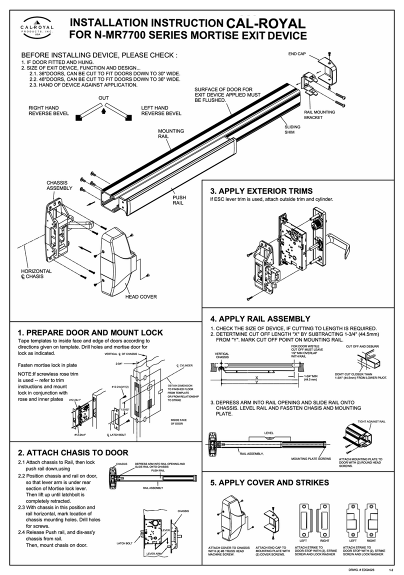
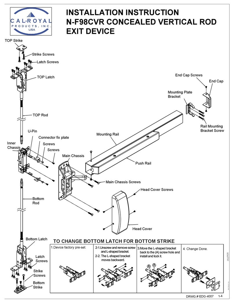
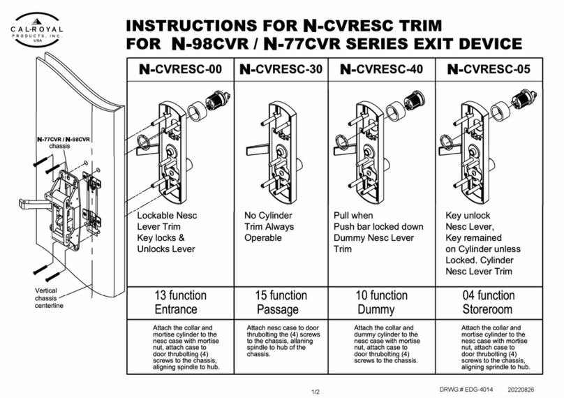
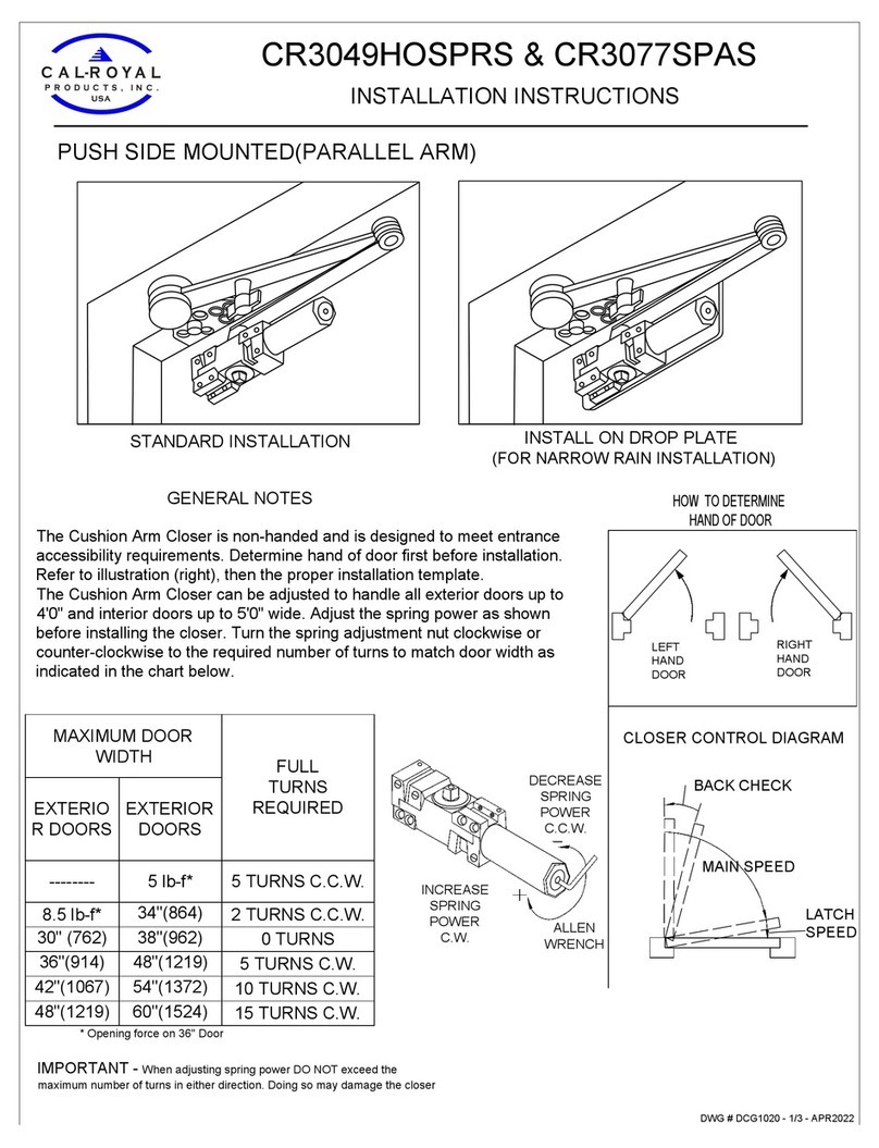
  9. Cal-Royal 8600 User manual

Cal-Royal 8600 User manual

CAL-ROYAL PRODUCTS Inc.
AUTOMATIC LOW ENERGY SWING DOOR OPERATOR
Operations & Installation Manual
These original installation instructions detailed within are solely forThese original installation instructions detailed within are solely for
professional Installers and not intended to be handed over to the end user.professional Installers and not intended to be handed over to the end user.
CAL-ROYAL PRODUCTS Inc.
6605 Flotilla Street, City of Commerce, CA 90040 USA
Tel.# (323) 888-6601, FAX# (323) 888-6699
WEB SITE: CAL-ROYAL.COM
Email: [email protected]
Ver. October 31, 2020
8600 Series
Installation Instruction
2 of 40
CAL-ROYAL PRODUCTS, INC.
6605 Flotilla St. Commerce CA 90040
Tel: (323) 888-6601; Fax: (323) 888-6699
Email: [email protected]; Website: www.calroyal.com
Please read these instructions carefully before installing the door operator. We are not responsible for
any loss or damage if these precautions are not followed.
These instructions should be followed to
avoid the possibility injury and damage due to wrong installation or adjustment
.
During maintenance and installation, the power to the control unit should be OFF.
Please use the correct power supply
–
Power Acceptance 90V~250V DC - 50 / 60 Hz
Make sure that the operator is grounded or connected to earth! The coating of the operator is made of
an electrically conductive metallic material, which will easily induce electrical conduction! Make sure the
ground or earth wire is connected!
The operator housing is not completely sealed, therefore it should be noted that excessive moisture or
a corrosive atmosphere could destroy the electronic components contained within.
Do not remove screws and bolts from the structure of the Control Unit or Motor Gear Box. Do not intend
to open, repair or alter any part of the operator unit. Failure to comply results in loss of warranty.
Installation and maintenance of this product can be performed by Trained and authorized personnel only.
Before switching ON the power supply, make sure that no objects obstruct the travel of the automatic
Doors.
NATIONAL WIRING REGULATIONS AND STANDARDS MUST BE CONFORMED TO.
Follow all indicated instructions as improper installation could cause severe damage.
Correct equipment must be used in order to reach overhead area for installation and service.
KEEP FINGERS & CLOTHING CLEAR OF ALL MOVING PARTS
Please keep these instructions.
WARRANTY 24 MONTHS FROM SHIPMENT - WARRANTY VOID IF REPAIR IS ATTEMPTED TO MOTOR GEAR
OR CONTROL ASSEMBLY
Failure to observe the information in this manual may result in personal injury or damage to equipment. To
reduce the risk of injury to persons - use this operator with single or double pedestrian swinging doors only.
Save these instructions for future reference.
AVOIDANCE OF ELECTRIC SHOCK, INJURY, FIRE OR MALFUNCTIONS
WARNING
8600 Series
Installation Instruction
3 of 40
CAL-ROYAL PRODUCTS, INC.
6605 Flotilla St. Commerce CA 90040
Tel: (323) 888-6601; Fax: (323) 888-6699
Email: [email protected]; Website: www.calroyal.com
1.0 PRODUCT SUMMARY
2.0 TECHNICAL SPECIFICATIONS
3.0 RECEIVING INSPECTION
4.0 PRE-INSTALLATION INFO
5.0 INSTALLATION
6.0 ARM(S) INSTALLATION
DOOR LEARNING CYCLE + START UP
7.0
ELECTRONICS CONTROLLER PROGRAMING
8.0
WIRING CONNECTIONS
9.0
HANDING OF OPERATOR
11.0 SAFETY SIGNAGE + DECALS
12.0 TROUBLE SHOOTING
13.0 DAILY SAFETY CHECK LIST
14.0 ADDITIONAL INFO
# SECTION
TABLE OF CONTENTS
8600 Series
Installation Instruction
4 of 40
CAL-ROYAL PRODUCTS, INC.
6605 Flotilla St. Commerce CA 90040
Tel: (323) 888-6601; Fax: (323) 888-6699
Email: [email protected]; Website: www.calroyal.com
When properly installed and programmed this product complies with ANSI/BHMA A156.19 Standard for Power
Assist and Low Energy Power Operated Swinging Doors.
It is the responsibility of the installer and/or installationcompany to certify that the final completed
Operator is installed in accordance with local building codes, applicable laws
and ANSI 156.19
standards
governing this product.
manual
8600 Series
Installation Instruction
5 of 40
CAL-ROYAL PRODUCTS, INC.
6605 Flotilla St. Commerce CA 90040
Tel: (323) 888-6601; Fax: (323) 888-6699
Email: [email protected]; Website: www.calroyal.com
1.0 Model 8600
2.0 Application Low Energy Swing Door Operator
3.0 Power Supply 90V ~ 250V AC, 50/60Hz
4.0 Consumption 100W Max
5.0 Motor 1/4 Hp, Low revolution 24VDC, 3A MAX
6.0 Rated Operation Continuous opening and closing cycles
7.0 Reduction Gear Enclosed Reduction Gear system
8.0 Control System Microprocessor Digital Control
9.0 Operating Environment
Ambient temperature -18 deg ~ +50 deg.
(no condensation or icing)
Ambient humidity 30% to 85%RH
(no hazardous materials must be present in
the atmosphere)
10.0 Operation During Power Failure Low manual resistance when opened by hand.
Door closing by spring.
11.0 Operator Net Weight 17kg Approx./ 38lbs
12.0 Operator Dimensions 5 ½” (H)(140 mm) x 4 ½” (D) (115mm)
13.0 Door Weight (max) 700 lbs (318kg) per leaf
14.0 Door Width Limits 29" up to 60" (Consult factory for Special Sizes)
15.0 Operator Width 29" - 102"
16.0 Installation Types Push, Pull, Overhead Concealed, Center spindle
17.0 Adjustable Opening Angle 80° - 180°
18.0 Auxiliary Power supply 1.2 Amps @ 24vdc for accessories
19.0 Closing Force Adjustable Pressure by Spring Tension and
optional motor close
20.0 Product Standards UL 325 Listed by ETL #5012330
ANSI 156.19 Compliant
Section # 2.0 - Technical Specification
8600 Series
Installation Instruction
6 of 40
CAL-ROYAL PRODUCTS, INC.
6605 Flotilla St. Commerce CA 90040
Tel: (323) 888-6601; Fax: (323) 888-6699
Email: [email protected]; Website: www.calroyal.com
If any of the below items are not correct, do not attempt to install the unit until all conditions are correct.
Report any incorrect items immediately.
NO CLAIMS FOR SHORTAGE WILL BE ACCECPTED UNLESS REPORTED WITHIN 24 HOURS OF RECEIPT
OF SHIPMENT. THE FOLLOWING ITMES SHOULD BE SUPPLIED:
No. Description Part No.
1 Screw end cover
2 Blank end cover
3 End cover plate Left
4 End cover bracket Left
5 Fixing Bolt
7 Control Unit 8600
8 8600 Housing
1
3
2
4
7
8
16
5
9 11
10
12
13
19 20
MH-8600
CU-8600
FB-8600
ECBL-8600
ECPL-8600
BEC-8600
SEC-8600
9 Motor
10 Motor gear box mount bracket
11 Gear Box
12 Spindle
13
16 Motor gear box end support bracket
19 End cover plate Right
20 End cover bracket Right
Mechanical door stop MDS-8600
ECBR- 8600
REP-8600
MEB-8600
S-8600
GB-8600
MGBMB-8600
M-8600
3
On receiving the package, please verify that the order was shipped complete and correct. Including model number,
header width, door handing, arm and color.
8600 Series
Installation Instruction
7 of 40
CAL-ROYAL PRODUCTS, INC.
6605 Flotilla St. Commerce CA 90040
Tel: (323) 888-6601; Fax: (323) 888-6699
Email: [email protected]; Website: www.calroyal.com
• t technicians are
• all is to the any or
maintenance.
•on any or parts.
•the operator or
• controls
the the
strictly
is
the the installer operator
A156.19 Standard for Power Assist and Low Energy Power
Operated Swing Doors, local
to complete the site inspection and into operation.
• A wiring must conform to standard wiring practice in accordance with national and local wiring codes.
• Door must swing freely through the entire opening and closing cycle before beginning of installation.
• Incorrectly installed or improperly adjusted door operators can cause property damage or personal
injury.
• A dimensions are given in inches (millimeters), unless otherwise note.
• Before installation, verify door frame is properly reinforced and is well anchored in the wall.
• Concealed electrical conduit and concealed switch or sensor wires should be pulled to the frame before
proceeding.
CAUTION
4.3 Electrical
lines into the the
clearly its correct
control to the operator to
these a installation.
is the the
to ease in the process.
the arm is the
in the correct
moving parts the the
any controls or accessories into the
any moving parts.
the motor is is no resistance against the
opening oror armarm closeclose veryvery
an electrical access hole is the
8600 Series
Installation Instruction
8 of 40
CAL-ROYAL PRODUCTS, INC.
6605 Flotilla St. Commerce CA 90040
Tel: (323) 888-6601; Fax: (323) 888-6699
Email: [email protected]; Website: www.calroyal.com
•Allen Wrench Set
•Power Drill and Drill Bits
•Level
•Tape Measure
•Wire Stripper
•Screwdrivers: Flat, Philip, 5/16” Hex.Nut
•Additional Fasteners Depending Surface
•Shims
•Hand Saw/ Power Saw
for
•#14 x 2-3/4” (70mm) long sheet metal screws for wood.
for
•#12, #14, Wood screws, Sheet Metal screws, Self-tapping screws of varying lengths depending on
applications.
•Typically, doors are hung on 4 ½” butt hinges or 3/4” (19mm) offset pivots.
fastener are use
need to
4 Required Tools for Installation
8600 Series
Installation Instruction
9 of 40
CAL-ROYAL PRODUCTS, INC.
6605 Flotilla St. Commerce CA 90040
Tel: (323) 888-6601; Fax: (323) 888-6699
Email: [email protected]; Website: www.calroyal.com
Operator
a
1
6
Battery Back-up Connection
COM
NO
NC
GND
12v
24v
8600 Series
Installation Instruction
10 of 40
CAL-ROYAL PRODUCTS, INC.
6605 Flotilla St. Commerce CA 90040
Tel: (323) 888-6601; Fax: (323) 888-6699
Email: [email protected]; Website: www.calroyal.com
Arm
that the operator is the correct orientation. Left Push, Right Push, Left Pull or Right Pull.
5.5 PULL Arm
• If the operator label is facing 'Down' to the floor, the handing is Left Hand Push/Pull.
• If the operator label is facing 'up' to the ceiling, the handing is Right Hand Push/Pull.
8600 Series
Installation Instruction
11 of 40
CAL-ROYAL PRODUCTS, INC.
6605 Flotilla St. Commerce CA 90040
Tel: (323) 888-6601; Fax: (323) 888-6699
Email: [email protected]; Website: www.calroyal.com
5.5 Operator Installation
Remove the cover from the assembly by
gently pulling the cover down with minimal effort.
Carefully s
Step 2. Remove the motor/gearbox and control
board from the back plate make through holes on
the back plate for mounting header where appropriate.
Note: Can be installed without removal of motor/gear box
and control board if preferred.
8600 Series
Installation Instruction
12 of 40
CAL-ROYAL PRODUCTS, INC.
6605 Flotilla St. Commerce CA 90040
Tel: (323) 888-6601; Fax: (323) 888-6699
Email: [email protected]; Website: www.calroyal.com
Step 3
.
Power Supply
Make sure all power i s turned OFF
before handling the supply wires.
electrician and w ithin the guidelines
of the enforced local electrical codes.
Drill holes f or the high voltage wires
in backing plate.
Pull the power supply i nto the header
at the same time as t he header
assembly is positioned.
Step 4. Fixing Operator in Place
B
e sure t here i s proper support i n
the wall to secure t he header at the
vertical jambs and behind t he
header a t intervals between t he
vertical jambs.
be required to compensate for any
gap between t he back o f base rail
and wall.
door frame, t hat access holes for
power supply cables are i n line, if
required
Secure the header box to the top of the door frame w ith the appropriate fasteners.
Holes can b e made anywhere i n header to secure. A ll holes MUST be drilled into substantial support
(studs, blocks, framing, etc.).
8600 Series
Installation Instruction
13 of 40
CAL-ROYAL PRODUCTS, INC.
6605 Flotilla St. Commerce CA 90040
Tel: (323) 888-6601; Fax: (323) 888-6699
Email: [email protected]; Website: www.calroyal.com
5-1/4
(133mm)
Step 5.
Once the header back plate is in place, install the motor/gearbox and control board to the header back plate
Slide the nuts (supplied with the operator) to hold the motor/gear box and control board along the 2 parallel tracks on
the back plate.
Fasten the bolt to hold the motor/gear box and control board in place.
The motor/gearbox needs to be installed so that the center of the spindle is 5 ¼" ( 133mm) from the end plate.
8600 Series
Installation Instruction
14 of 40
CAL-ROYAL PRODUCTS, INC.
6605 Flotilla St. Commerce CA 90040
Tel: (323) 888-6601; Fax: (323) 888-6699
Email: [email protected]; Website: www.calroyal.com
Push Pull
Following these simple steps will allow the door to be set up quickly and correctly. Refer to installation
drawings below.
Notes: Base rail to be mounted flush with the bottom of the door frame.
A solid spacer material or filler may be required to compensate for any gap between the back of base rail and
wall. Ensure, before fixing base rail to the door frame, t hat access holes for power supply cables are in line,
if required
Without arm fitted, set 3-position switch to Hold Open (II. The drive shaft with turn fully until hitting the
in-built fixed doorstop, so charging the spring.
Step 2. With door closed
in
below at
8600 Series
Installation Instruction
15 of 40
CAL-ROYAL PRODUCTS, INC.
6605 Flotilla St. Commerce CA 90040
Tel: (323) 888-6601; Fax: (323) 888-6699
Email: [email protected]; Website: www.calroyal.com
Step 3. Manually open the door to
the full open position (Approx. 100deg
open position).
,
Line up Rod with Push Arm,
sliding Rod into Push Arm and
tighten bolts.
Step 4. Set 3-position switch to
manual (0) and allow door to close
under spring pressure.
Test and adjust arm at full closed
position as necessary so door
closes fully with frame.
Step 5. Press Test/Learn button to begin the learning cycle. See Learning Door Cycle.
Fit PUSH arm to the drive
shaft at the full open position,
close door and tighten arm.
8600 Series
Installation Instruction
16 of 40
CAL-ROYAL PRODUCTS, INC.
6605 Flotilla St. Commerce CA 90040
Tel: (323) 888-6601; Fax: (323) 888-6699
Email: [email protected]; Website: www.calroyal.com
Turn 3-position switch to automatic (I). Press Test/Learn button to begin the learning cycle.
See Learning Door Cycle.
Manually open the
door to full Step 2. Manually
open the door to full open
(Approx. 100deg open
position).
Fit PULL arm to the drive
shaft at the full open position
so t he roller touches t he
door.
Mark the open position
where roller touches the
door.
Set 3-position
switch to manual (0) and
allow the door to close
under spring power.
Mark the closed position
where the roller touches the
door.
4. Position slide track
horizontally within 1st and
2nd mark, then fix it to the
door.
Slide the roller along the
channel, followed by fitting
end caps.
6.2 PULL / SLIDE TRACK STANDARD ANGLE ARM 0" - 4" REVEALS
Notes: Operator to be mounted so that base of drive shaft is clear above the door top. See Installation Drawings.
A solid spacer material or filler may be required to compensate for any gap between the back of base rail and
wall. Ensure, before fixing base rail to the door frame, that access holes for power supply cables are in line, if
required
Without PULL arm fitted, set 3-position switch to Hold Open (II). The drive shaft with turn fully until hitting
the in-built fixed doorstop, so charging the spring.
8600 Series
Installation Instruction
17 of 40
CAL-ROYAL PRODUCTS, INC.
6605 Flotilla St. Commerce CA 90040
Tel: (323) 888-6601; Fax: (323) 888-6699
Email: [email protected]; Website: www.calroyal.com
THIS PAGE LEFT INTENTIONALY BLANK
8600 Series
Installation Instruction
18 of 40
CAL-ROYAL PRODUCTS, INC.
6605 Flotilla St. Commerce CA 90040
Tel: (323) 888-6601; Fax: (323) 888-6699
Email: [email protected]; Website: www.calroyal.com
ycyclele + Start u+ Start upp
“TEST/LEARN” button is currently used for two functions.
a. TEST an
b. LEARN a
Note: The built-in mechanical doorstop should only act as a limiting device should the door
be pushed past it's pre-set electroncally selected open position
Step
a
8600 Series
Installation Instruction
19 of 40
CAL-ROYAL PRODUCTS, INC.
6605 Flotilla St. Commerce CA 90040
Tel: (323) 888-6601; Fax: (323) 888-6699
Email: [email protected]; Website: www.calroyal.com
Section # 8.0 - Electronics Controller Programming
∞ Programming is quick and simple via the visual LED display
∞ Each FUNCTION is clearly shown on the display in text, words and symbols
∞ The VALUE or APPLICATION can easily be adjusted using the buttons on the face of the controller
∞ Changed menu values will automatically be saved during the next opening cycle
SPECIAL WARNING
All Menu Values and Settings must comply with ANSI/BHMA A156.19 Standard
for Power Assist and Low Energy Power Operated Swing Doors
8.1.
Opening Speed (05-12 for Low Energy) or (05-20 for Full Automatic)
∞ This setting is the door “Opening” speed from the fully closed position to the back-check position
∞ Use the “UP” and “DOWN” buttons to select the desired door opening speed
∞ Activate the door to check the speed is correctly adjusted
8.2.
Back-check Speed (01-05)
∞ This setting is speed when the door reaches the back-check position to the full door opening
∞ Use the “UP” and “DOWN” buttons to select the desired door back-check speed
∞ Activate the door to check the speed is correctly adjusted
8.3.
Safety Speed (Hold/Crawl)
∞ This setting is door speed when “Safety 2” is active during the opening cycle
∞ Use the “UP” and “DOWN” buttons to select either Hold or Crawl speed
8.4.
Closing Speed (01-15)
∞ This setting is the door “Closing” speed from the fully opened position to the Latch area
∞ Use the “UP” and “DOWN” buttons to select the desired door “Closing” speed
∞ Activate the door to check the speed is correctly adjusted
8.5.
Latch Speed (01-05)
∞ This setting is the door “Closing” speed in the Latch area until fully Closed
∞ Use the “UP” and “DOWN” buttons to select the desired door “Latching” speed
∞ Activate the door to check the speed is correctly adjusted
8.6.
Current Limit (01-20)
∞ In case the door encounters an obstruction during the Opening cycle, once the maximum Current limit
is reached for at least 2 seconds, the door Opening is then canceled
∞ Use the “UP” and “DOWN” buttons to select the desired “Current” limit strength
∞ Activate the door to Open. During the Opening cycle, physically apply pressure to stall the door for at
least 2 seconds
∞ Check the force needed to reach the limit at which the door Opening is canceled
∞ Increase or Decrease this setting to achieve the correct strength needed
∞ Note: Setting of 10 is sufficient for most all applications
8.7.
Activation Time (01-60 seconds)
∞ This setting is the duration of the door Open cycle in seconds
∞ The timer starts when the door starts to activate
∞ Use the “UP” and “DOWN” buttons to select the desired “Opening” time
8600 Series
Installation Instruction
20 of 40
CAL-ROYAL PRODUCTS, INC.
6605 Flotilla St. Commerce CA 90040
Tel: (323) 888-6601; Fax: (323) 888-6699
Email: [email protected]; Website: www.calroyal.com
8.8. Hold On Manual Open (No or 01-05 seconds)
∞ This setting is the length of time the door will be physically held Open, when the door is “Manually”
pushed or pulled open by a pedestrian
∞ The door must be opened at least 60% of the door swing, for this feature to activate
∞ Use the “UP” and “DOWN” buttons to Enable or Disable this feature and set the timer value to keep
open
∞ Caution: do not set timer for more than 1.0 seconds unless requested by the end user
8.9.
Electronic Door Stop (Yes/No)
∞ This feature is always Enabled even if you select Disabled
8.10
. Electric Lock (Yes/No)
∞ This setting is to Enable or Disable the electric Lock/Strike through the Control unit
∞ Select No when there is not an electric Lock
∞ Use the “UP” and “DOWN” buttons to set the proper Electric Lock
8.11
. Electric Lock Delay (0.2-2.0 seconds)
∞ This setting is the length of time in seconds for the Delay between activating the Electric Lock and the
Start of the Opening cycle
∞ Use the “UP” and “DOWN” buttons to Disable or Enable the electronic Delay/Output
∞ Note: Setting of 0.2 seconds is sufficient for most applications
8.12
. Latch Position (2%-30%)
∞ This setting will adjust the door Latch position during the Closing cycle
∞ Use the “UP” and “DOWN” buttons to set the starting point for the Latch position
∞ Activate the door. During the Closing cycle, check the Latch starting position where the door begins to
slow down
∞ Check this setting is correctly adjusted
∞ If stack pressure is preventing the door from Fully Closing set at 30% and activate the Power Close
feature
8.13
. Backcheck Position (70%-98%)
∞ This setting is to adjust the door Back-check position of the Opening cycle
∞ Use the “UP” and “DOWN” buttons to set the starting point for the Back-check position
∞ Activate the door. During the Opening cycle, check the position where the Back-check begins and the
door starts to slow down
∞ Check this setting is correctly adjusted
∞ In windy conditions set to 70%
8.14
. Push & Go (Yes/No)
∞ This setting is to Enable or Disable the Push & Go feature, also known as Manual Activation, when the
door is Manually pushed or pulled open by hand
∞ Caution: do not activate this feature without training and specifically requested by the end user
∞ Use the “UP” and “DOWN” buttons to Disable or Enable this feature
8.15
. Push & Go Active Time (01-30 seconds)
∞ This setting is to adjust the duration of the door Open cycle in seconds from when the door is Manually
pushed Open to when the Push & Go feature is enabled
∞ Use the “UP” and “DOWN” buttons to select the desired Opening time

Other manuals for 8600

1

Other Cal-Royal Door Opening System manuals
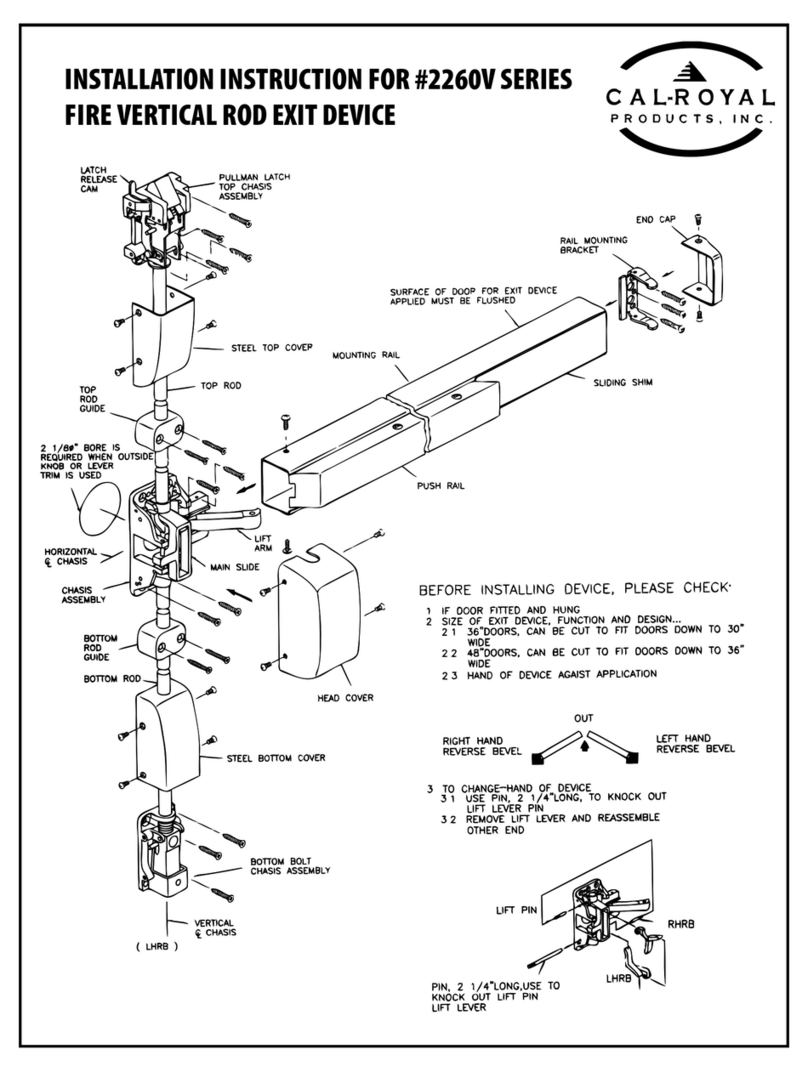
Cal-Royal CR3049HOSPRS User manual

Cal-Royal

Cal-Royal CR3049HOSPRS User manual

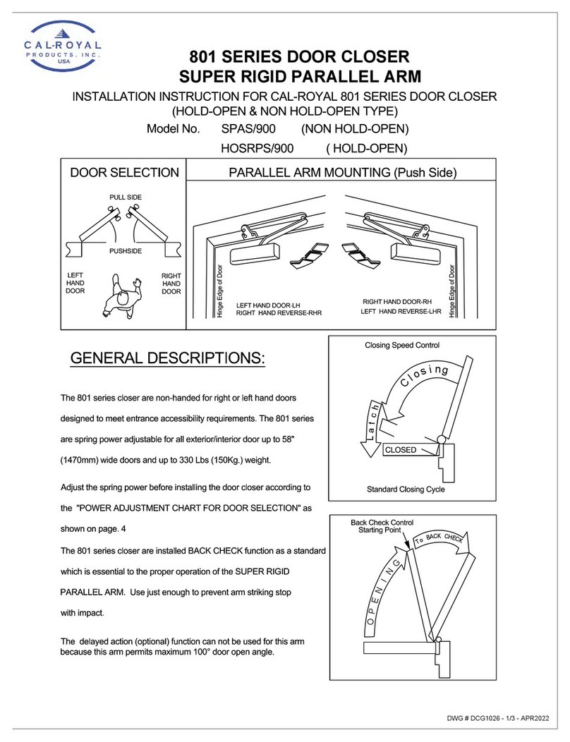
Cal-Royal 801 Series User manual

Cal-Royal

Cal-Royal 801 Series User manual

Cal-Royal 2260V Series User manual

Cal-Royal

Cal-Royal 2260V Series User manual
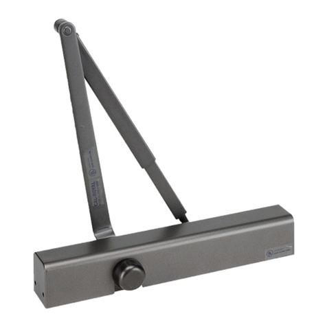
Cal-Royal N-77CVR User manual

Cal-Royal

Cal-Royal N-77CVR User manual

Cal-Royal 7760V Series User manual

Cal-Royal

Cal-Royal 7760V Series User manual

Cal-Royal 22-3PT User manual

Cal-Royal

Cal-Royal 22-3PT User manual

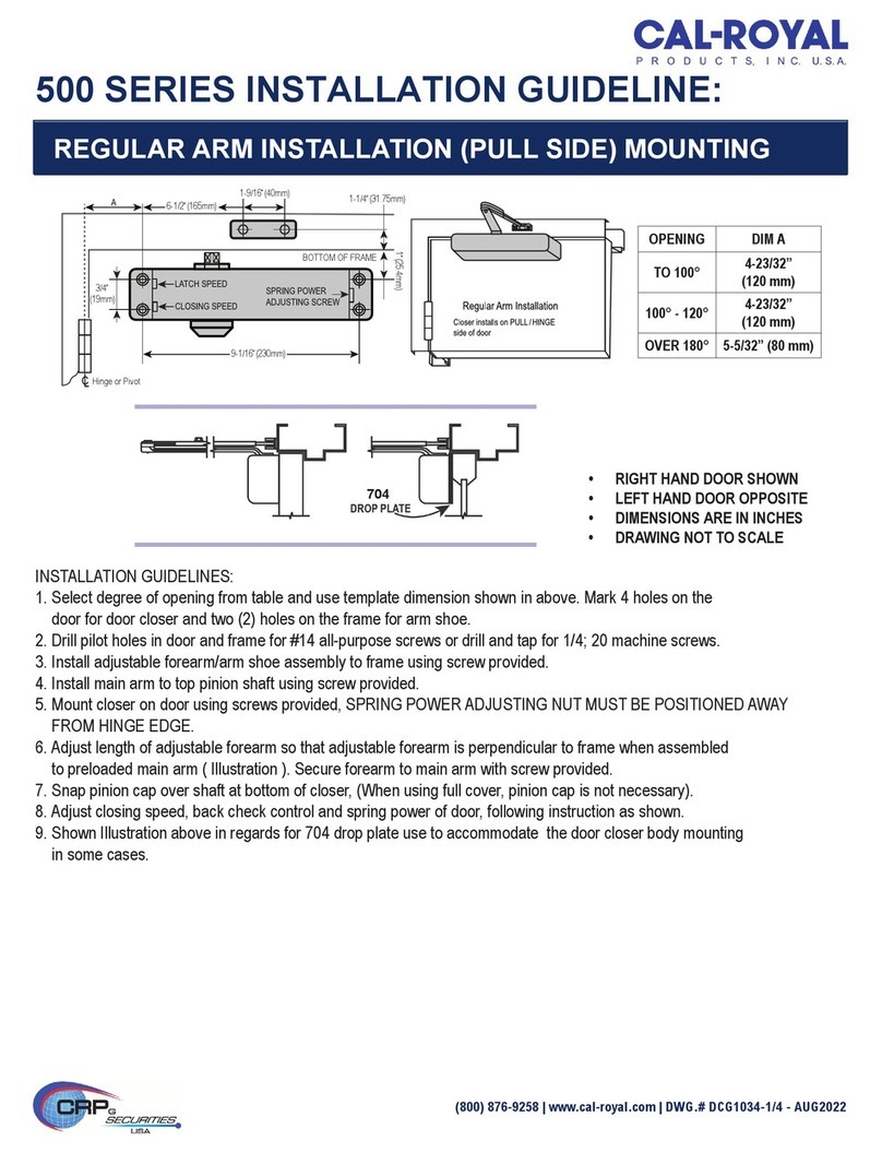
Cal-Royal 500 Series Instruction sheet

Cal-Royal

Cal-Royal 500 Series Instruction sheet

Cal-Royal N-CVRESC User manual

Cal-Royal

Cal-Royal N-CVRESC User manual

Cal-Royal N900 Series User manual

Cal-Royal

Cal-Royal N900 Series User manual

Cal-Royal N-FMR7700 Series User manual

Cal-Royal

Cal-Royal N-FMR7700 Series User manual

Cal-Royal N-MR7700 Series User manual

Cal-Royal

Cal-Royal N-MR7700 Series User manual

Cal-Royal CR801 Series User manual

Cal-Royal

Cal-Royal CR801 Series User manual

Cal-Royal 98-3PT User manual

Cal-Royal

Cal-Royal 98-3PT User manual

Cal-Royal N-F98CVR User manual

Cal-Royal

Cal-Royal N-F98CVR User manual

Cal-Royal 8600 User manual

Cal-Royal

Cal-Royal 8600 User manual

Cal-Royal A2260V Series User manual

Cal-Royal

Cal-Royal A2260V Series User manual

Cal-Royal N-F77CVR User manual

Cal-Royal

Cal-Royal N-F77CVR User manual

Cal-Royal 900 Series User manual

Cal-Royal

Cal-Royal 900 Series User manual
Popular Door Opening System manuals by other brands

Nabco GYRO TECH GT-1175 Wiring and Programming Manual

Nabco

Nabco GYRO TECH GT-1175 Wiring and Programming Manual

Record K 32 M user manual

Record

Record K 32 M user manual

QUAD EZ-4000 Owners and installation manual

QUAD

QUAD EZ-4000 Owners and installation manual

EZ-ACCESS CONCIERGE 23DR installation manual

EZ-ACCESS

EZ-ACCESS CONCIERGE 23DR installation manual

Woelm HELM GT-L 50 installation instructions

Woelm

Woelm HELM GT-L 50 installation instructions

Assa Abloy Corbin Russwin PED4000 Series installation instructions

Assa Abloy

Assa Abloy Corbin Russwin PED4000 Series installation instructions

CAME MI1010 quick start guide

CAME

CAME MI1010 quick start guide

Benninca VN.15C operating instructions

Benninca

Benninca VN.15C operating instructions

Locinox VERTICLOSE-RAIL Installation instructions manual

Locinox

Locinox VERTICLOSE-RAIL Installation instructions manual

Akerstroms Sesam 500 Technical guide

Akerstroms

Akerstroms Sesam 500 Technical guide

hager 9850 Installation instructions manual

hager

hager 9850 Installation instructions manual

BEA Falcon Assembly Dimensional drawing

BEA

BEA Falcon Assembly Dimensional drawing

Assa Abloy SARGENT 351 installation instructions

Assa Abloy

Assa Abloy SARGENT 351 installation instructions

Dorma 8900 DS quick start guide

Dorma

Dorma 8900 DS quick start guide

Iseo ACE IS9100 Mounting instructions

Iseo

Iseo ACE IS9100 Mounting instructions

Door Controls DC One installation manual

Door Controls

Door Controls DC One installation manual

Lamp FD30-F installation manual

Lamp

Lamp FD30-F installation manual

Yale 3040 installation instructions

Yale

Yale 3040 installation instructions

manuals.online logo
manuals.online logoBrands
  • About & Mission
  • Contact us
  • Privacy Policy
  • Terms and Conditions

Copyright 2025 Manuals.Online. All Rights Reserved.