manuals.online logo
Brands
  1. Home
  2. •
  3. Brands
  4. •
  5. Cal-Royal
  6. •
  7. Door Opening System
  8. •
  9. Cal-Royal 900 Series User manual

Cal-Royal 900 Series User manual

900 SERIES
SUPER RIGID PARALLEL ARM
INSTALLATION INSTRUCTION FOR
CAL-ROYAL 900 SERIES DOOR CLOSERS
(HOLD-OPEN & NON HOLD-OPEN TYPE)
Model No. SPAS/900 (NON HOLD-OPEN)
HOSRPS/900 ( HOLD-OPEN)
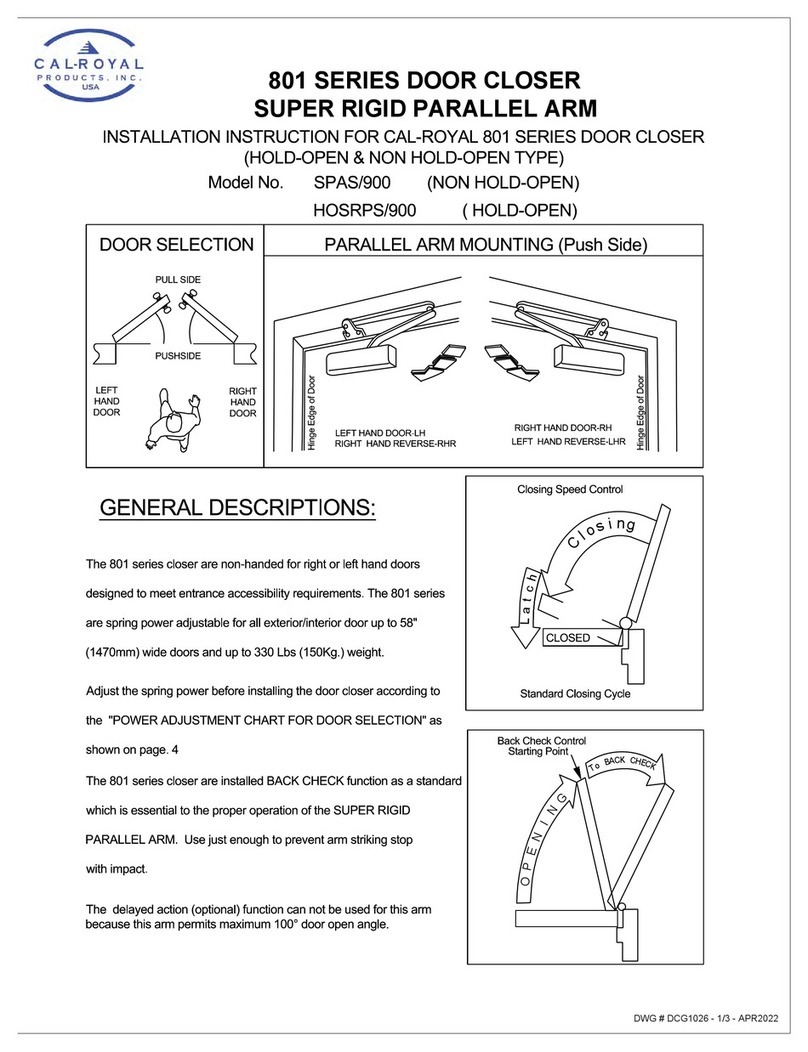
DOOR SELECTION
PULL SIDE
PUSHSIDE
LEFT
HAND
DOOR
RIGHT
HAND
DOOR
PARALLEL ARM MOUNTING (Push Side)
Hinge Edge of Door
LEFT HAND DOOR-LH
RIGHT HAND REVERSE-RHR
RIGHT HAND DOOR-RH
LEFT HAND REVERSE-LHR
Hinge Edge of Door
GENERAL DESCRIPTIONS:
The 900 series closer are non-handed for right or left hand doors
designed to meet entrance accessibility requirements. The 900 series
are spring power adjustable for all exterior/interior door up to 58"
(1470mm) wide doors and up to 330 Lbs (150Kg.) weight.
Adjust the spring power before installing the door closer according to
the "POWER ADJUSTMENT CHART FOR DOOR SELECTION" as
shown on page. 4
The 900 series closer are installed BACK CHECK function as a standard
which is essential to the proper operation of the SUPER RIGID
PARALLEL ARM. Use just enough to prevent arm striking stop
with impact.
The delayed action (optional) function can not be used for this arm
because this arm permits maximum 100° door open angle.
Closing Speed Control
Back Check Control
Standard Closing Cycle
CLOSED
Starting Point
T
o
B
A
C
K
C
H
E
C
K
C
l
o
s
i
n
g
L
a
t
c
h
O
P
E
N
I
N
G
1 of 4
LEFT HAND DOOR
DOOR STOP
DOOR STOP
PARALLEL ARM (PUSH SIDE) MOUNTING
LEFT HAND DOOR SHOWN
8-1/4"
·DIMENSION ARE IN INCHES
·RIGHT HAND DOOR OPPOSITE
·DO NOT SCALE
PARALLEL ARM (PUSH SIDE) MOUNTING
RIGHT HAND DOOR SHOWN
8-1/4""
4-7/8"
3-3/8"
4 7/8"
11-1/8"
2-7/8"
STOP
FACE
DOOR
EDGE
BRACKET
BRACKET
11-1/8"
2-7/8"
3-3/8"
BACKCHECK CONTROL CLOSING SPEED
LATCH SPEED
SPRING ADJUSTING NUT
BACKCHECK CONTROL
CLOSING SPEED
LATCH SPEED
SPRING ADJUSTING NUT
·DIMENSION ARE IN INCHES
·RIGHT HAND DOOR OPPOSITE
·DO NOT SCALE
RIGHT HAND DOOR
INSTALLATION INSTRUCTION
Model No. : SPAS/900 (NON HOLD-OPEN TYPE)
HOSRPS/900 (HOLD-OPEN TYPE)
STOP
FACE
DOOR
EDGE
2 of 4
5/16 OR 8mm
HEX WRENCh of door (refer to page 1) THE HAND MUST BE CORRECT
BEFOR THE BRACKET IS MOUNTED TO THE DOOR STOP (TOP JAMB).
FOR LEFT HAND DOORS:
All bracket are shipped assembled for LEFT HAND DOOR. Insert 5/16"
(8mm) hex wrench into ARM STOP and turn anti-clockwise to seat as tightly
as possible.
Push filler plug in firmly.
FOR RIGHT HAND DOORS:
Push filler plug out of bracket
Using a 5/16" (8mm) hex wrench turn ARM STOP clockwise to remove from
bracket insert in hole marked "R". Turn hex wrench clockwise to seat ARM
STOP as tightly as possible. Push filler into other hole.
BRACKET
ARM STOP
FILLER PLUS
INTERCHANGEBLE FOR DOOR HANDING
Left Hand Door
MAIN ARM
CAUTION
IMPROPER INSTALLATION OR REGULATION
MAY RESULT IN PERSONAL INJURY OR
PROPERTY DAMAGE FOLLOW ALL
INSTRUCTION CAREFULLY.
WRENCH
hold open control handle
stud
forearm
MAIN ARM
REMOVABLE
INSERTS
SHAFT
SCREW
Sackcheck valve
SPRING
ADJUSTING NUT
INSTALLATION SEQUENCE
LEFT HAND DOOR SHOWN - RIGHT HAND DOOR OPPOSITE
IMPORTANT REMARK
1. Adjusting spring power to match door width or weight as
indicated by DOOR SELECTION CHART shown on page 4.
2. Mount closer on door to dimensions shown on page 2.
3. Attach MAIN ARM as follows:
(a) Remove stud at junction between MAIN ARM and FOREARM
(b) -IMPORTANT- place open end wrench (spanner) on bottom
shaft and turn toward hinge edge about 45°
(c) place MAIN ARM on top shaft parallel with door and secure
with shaft screw with wrench (13/32" or 10mm)
4. Attach BRACKET to door stop (Top jamb) as shown on page 2.
5. Swing door open about 45° join main and forearm insert stud and tighten securely.
REGULATION
Do not allow door to slam into frame.
A normal standard closing time from 90° open position is 5 to 7
seconds evenly divided between main closing (sweep) speed and
latching speed Adjust the CLOSING speed first, then adjust the
LATCHING speed.
For slow closing speed of door turn speed adjusting valve of "C"
(closing speed) clockwise and anti-clockwise for fast.
Latching speed control of door is the same manner as closing speed adjustment.
ADJUSTABLE BACK CHECK FUNCTION
This function is essential to the proper operation of the SUPER
RIGID PARALLEL ARM. Use just enough to prevent arm to striking
stop with impact. See page 4.
ATTACH COVER
Slide cover insert into the un-used cutout in cover.
Install cover securely using screw provided.
HOW TO HOLD-OPEN (90° STOP)
A quarter turn on the HOLD-OPEN CONTROL HANDLE engages or
disengages hold-open.
APPROX
45°
45°
3 of 4
DOOR CLOSER SIZE CLOCKWISE TURNS OF
ADJUSTIN NUT APPLICABLE DOOR SIZE APPLICABLE
DOOR
WEIGHT
900-P/PDA
(SIZE 1/2-6)
900-FBF/BFDA
(SIZE 1/2-4)
900-P/PDA
(SIZE 2-6)
900-PBF/BFDA
(SIZE 1/2-4) INTERIOR EXTERIOR
(SWING OUT)
NOT RECOMMEND
USE 900-PBF/BFDA 12N/A • -9 28"(0.71m) 24"(0.51m) 22-33 Lbs
(10-15kg)
NOT RECOMMEND
USE 900-PBF/BFDA 1 N/A • -6 32"(0.81m) 28"(0.71m) 33-55 Lbs
(15-30kg)
2 2 • -3 • -3 36"(0.91m) 32"(0.81m) 55-88 Lbs
(30-45kg)
3 3 0
(FACTORY SET)
0
(FACTORY SET) 42"(1.07m) 38"(0.91m) 88-143 Lbs
(45-85kg)
4 4 3 3 48"(1.22M) 42"(1.07m) 143-187 Lbs
(65-85kg)
5
NOT
RECOMMEND
USE 900-P/PDA 6N/A 54"(1.37m0 48"(1.22M) 187-264 Lbs
(85-120kg)
6
NOT
RECOMMEND
USE 900-P/PDA 9 N/A 58"(1.47m) 52"(1.37m0 264-330 Lbs
(120-150kg)
T
o
B
A
C
K
C
H
E
C
K
O
P
E
N
I
N
G
Back Check Control
POWER ADJUSTMENT CHART FOR DOOR SELECTIONS
Spring Power Control HOW TO ADJUST SPRING POWER
To increase opening force and closing force
turn the spring adjusting nut clockwise.
To decrease opening force and closing force
turn the spring adjusting nut anticlockwise.
BE NOTED THAT 900 SERIES ARE SET DOWN AS DOOR CLOSER SIZE 3 FROM THE FACTORY.
EX: SIZE 2 CLOSER CAN BE MADE BY ROTATING SPRING ADJUSTING NUT ANTI-CLOCKWISE 3 TURNS
BECAUSE IT WAS SET DOWN AS SIZE 3 FROM THE FACTORY ORIGINALLY. ALSO IN A SAME WAY.
SIZE 6 CLOSER CAN BE MADE BY ROTATING SPRING ADJUSTMENT NUT CLOCKWISE 9 TURNS.
Increase
Decrease
SPRING
ADJUSTING NUT
NOTE: MAXIMUM ADJUSTMENT
IS APPROXIMATELY 10 TURNS.
DO NOT FORCIBLY EXTEND.
ADJUSTMENT BEYOND LIMITS.
Decrease
Increase Backcheck Valve
·To increase back check intensity, turn back
check control valve clockwise.
·To decrease back check intensity, turn
back check control valve counterclockwise.
·NEVER close this valve completely OPENING Cycle
INSTRUCTION FOR INSTALLATING
BRACKET SUPPORT ("L" SUPPORT)
SUPPORT
"L"
1/4-20 MACHINE SCREW
(2 PCS REQUIRED)
FRAME
DOOR
STOP
DOOR
BRACKET
"PLEASE DRILL & TAP HERE"
(AFTER BRACKET IS INSTALLED)
IT frame (or door stop) is not wide enough to fix the bracket wholly use "L" support to
support and fasten between the frame and bracket as shown below:
HOW TO INSTALL
1. Set "L" support on top of bracket and hold & match with frame.
2. Fasten the 2 pieces of 1/4-20 machine screws to the frame.
3. To the proper position. DRILL & TAP one or two holes of 1/4-20
from the bracket through "L" support.
4. Tighten the 1/4-20 screw(s) securely.
·-3 Mean 3 turn anti-clockwise
4 of 4

This manual suits for next models

2

Other Cal-Royal Door Opening System manuals
Cal-Royal 98-3PT User manual

Cal-Royal

Cal-Royal 98-3PT User manual

Cal-Royal 7760V Series User manual

Cal-Royal

Cal-Royal 7760V Series User manual

Cal-Royal N900 Series User manual

Cal-Royal

Cal-Royal N900 Series User manual

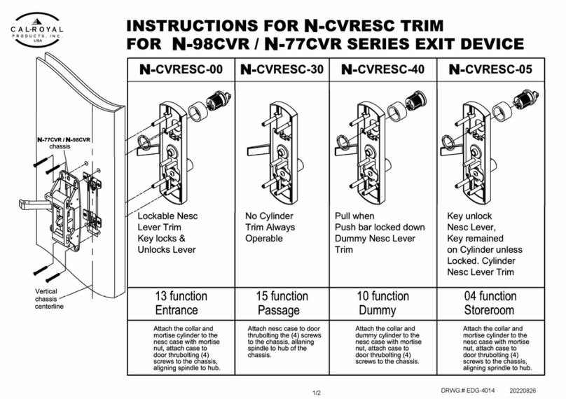
Cal-Royal N-CVRESC User manual

Cal-Royal

Cal-Royal N-CVRESC User manual

Cal-Royal 8600 User manual

Cal-Royal

Cal-Royal 8600 User manual

Cal-Royal 2260V Series User manual

Cal-Royal

Cal-Royal 2260V Series User manual
Cal-Royal N-FMR7700 Series User manual

Cal-Royal

Cal-Royal N-FMR7700 Series User manual

Cal-Royal A2260V Series User manual

Cal-Royal

Cal-Royal A2260V Series User manual

Cal-Royal CR3049HOSPRS User manual

Cal-Royal

Cal-Royal CR3049HOSPRS User manual

Cal-Royal N-F77CVR User manual

Cal-Royal

Cal-Royal N-F77CVR User manual

Cal-Royal 22-3PT User manual

Cal-Royal

Cal-Royal 22-3PT User manual

Cal-Royal CR801 Series User manual

Cal-Royal

Cal-Royal CR801 Series User manual
Cal-Royal N-F98CVR User manual

Cal-Royal

Cal-Royal N-F98CVR User manual

Cal-Royal 801 Series User manual

Cal-Royal

Cal-Royal 801 Series User manual

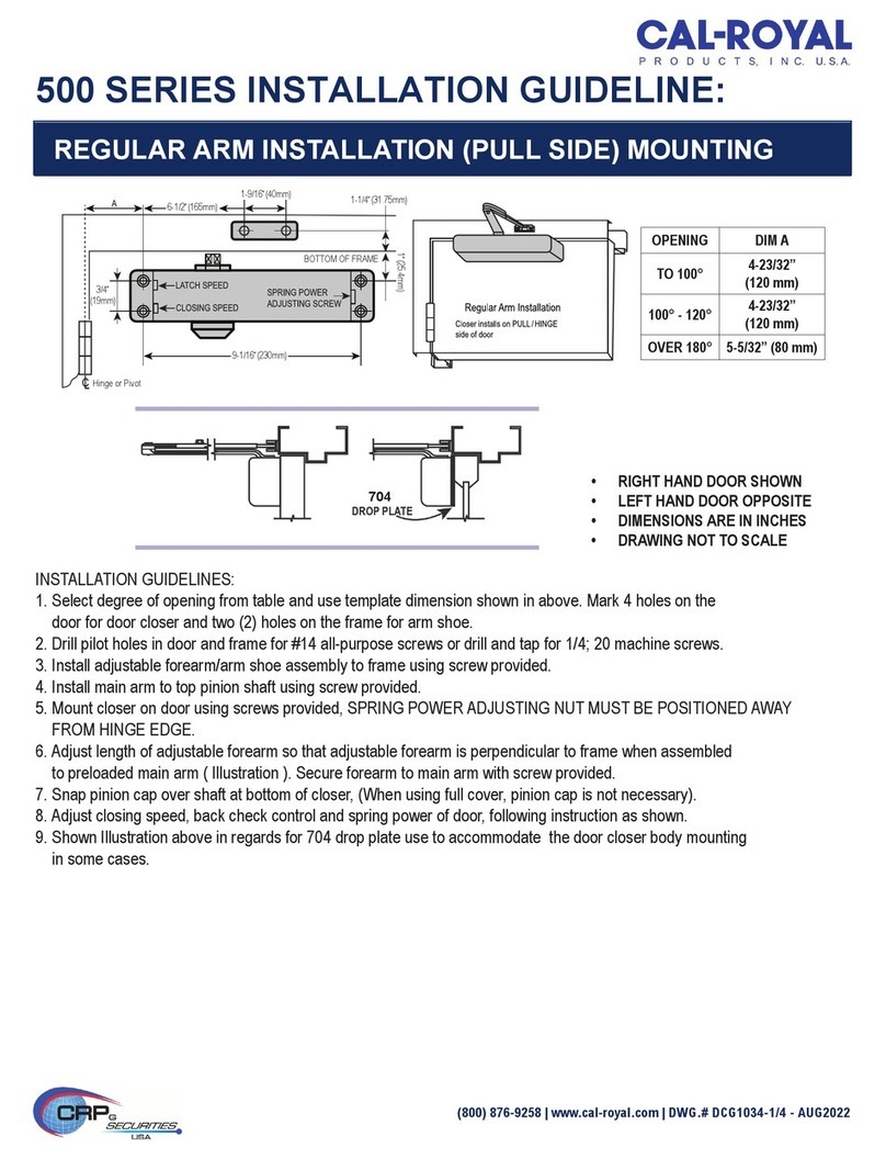
Cal-Royal 500 Series Instruction sheet

Cal-Royal

Cal-Royal 500 Series Instruction sheet

Cal-Royal N-77CVR User manual

Cal-Royal

Cal-Royal N-77CVR User manual

Cal-Royal 8600 User manual

Cal-Royal

Cal-Royal 8600 User manual

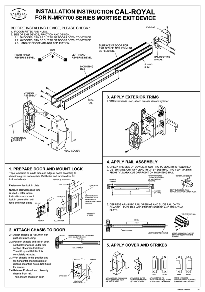
Cal-Royal N-MR7700 Series User manual

Cal-Royal

Cal-Royal N-MR7700 Series User manual

Popular Door Opening System manuals by other brands

Henderson HUSKY 50 Fitting instructions

Henderson

Henderson HUSKY 50 Fitting instructions

Assa Abloy Norton 6300 Series installation instructions

Assa Abloy

Assa Abloy Norton 6300 Series installation instructions

Celegon COMPACK LIVING 90 Construction manual

Celegon

Celegon COMPACK LIVING 90 Construction manual

GILGEN SLM manual

GILGEN

GILGEN SLM manual

Fireco Dorgard SmartSound user guide

Fireco

Fireco Dorgard SmartSound user guide

Assa Abloy Adams Rite EX76 Preparation Guide and Installation Instructions

Assa Abloy

Assa Abloy Adams Rite EX76 Preparation Guide and Installation Instructions

Bohle BO 5215496 instruction manual

Bohle

Bohle BO 5215496 instruction manual

FAAC XKPR125D manual

FAAC

FAAC XKPR125D manual

Aprimatic BA 230 Electrical installation, Use and Maintenance instructions

Aprimatic

Aprimatic BA 230 Electrical installation, Use and Maintenance instructions

Savio SUMMA quick start guide

Savio

Savio SUMMA quick start guide

Roto E-Tec DoorDrive Installation, maintenance and operation instructions

Roto

Roto E-Tec DoorDrive Installation, maintenance and operation instructions

Assa Abloy Norton 1600H Series installation instructions

Assa Abloy

Assa Abloy Norton 1600H Series installation instructions

SECO-LARM Enforcer SD-C141S installation manual

SECO-LARM

SECO-LARM Enforcer SD-C141S installation manual

hawa HAWA-Motronic 60 Installation and commissioning instructions

hawa

hawa HAWA-Motronic 60 Installation and commissioning instructions

GEZE Powerdrive PL-HT installation instructions

GEZE

GEZE Powerdrive PL-HT installation instructions

raumplus 800 AIR-B Series Assembly & installation

raumplus

raumplus 800 AIR-B Series Assembly & installation

D+H BAZ 04-N-UT Original instructions

D+H

D+H BAZ 04-N-UT Original instructions

Langer & Laumann QKS6 user manual

Langer & Laumann

Langer & Laumann QKS6 user manual

manuals.online logo
manuals.online logoBrands
  • About & Mission
  • Contact us
  • Privacy Policy
  • Terms and Conditions

Copyright 2025 Manuals.Online. All Rights Reserved.