Instruction manual, March 2016 Page 2
1Introduction
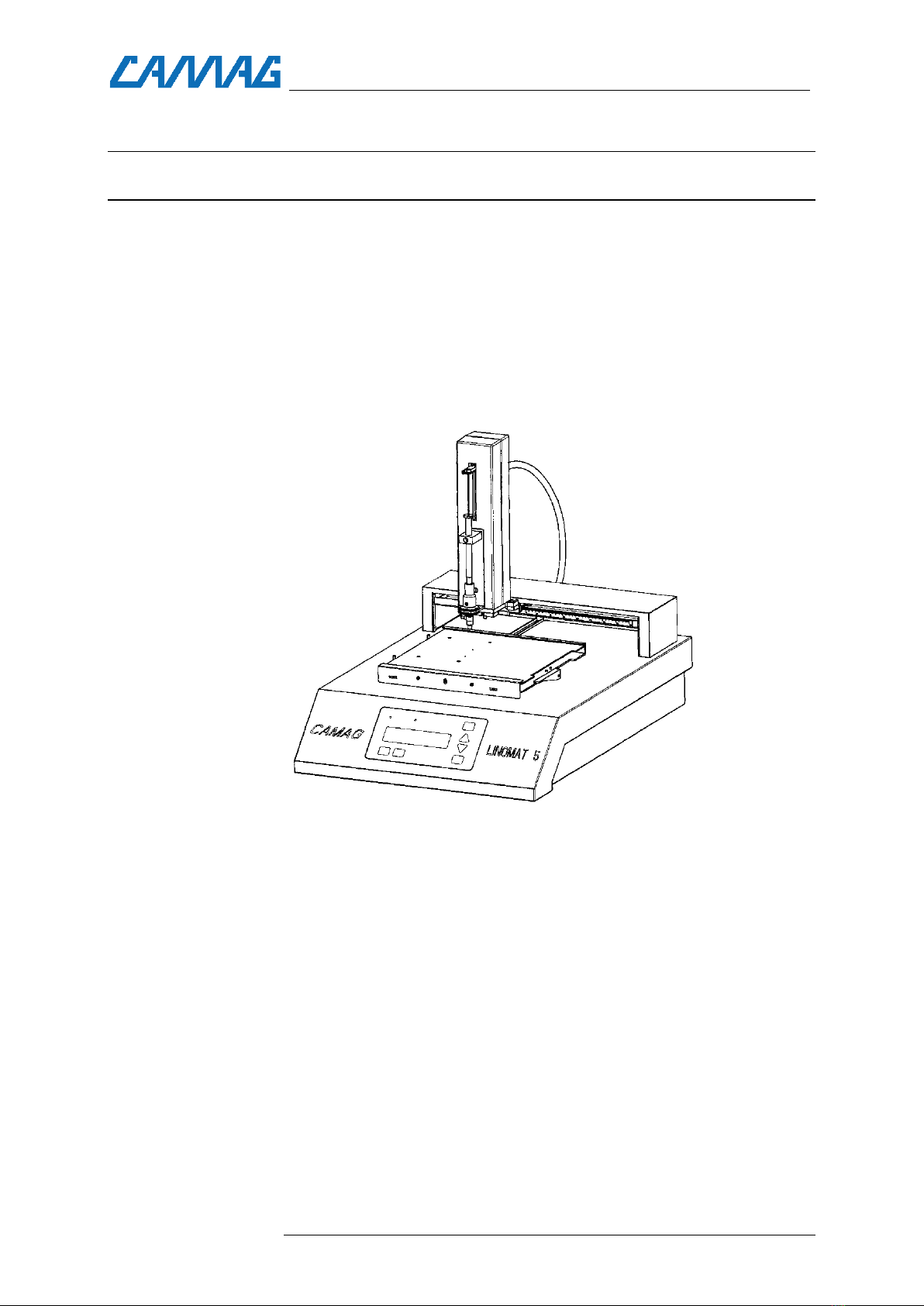
1.1 CAMAG Linomat 5
The CAMAG Linomat 5 is a semiautomatic sample application de-
vice for use in qualitative, quantitative and preparative Thin-layer
chromatography. The Linomat 5 is shipped with EquiLink, RS232
cable and built in interface for connecting to a computer from
which the instrument can be programmed.
The parameters for up to 10 application programs can be stored
for stand-alone operation without PC- control.
The Linomat 5 is software controlled, visionCATS/winCATS con-
trols and reports all parameters and steps of the TLC analysis in-
cluding definition of plate material, sample application, derivatiza-
tion, development and evaluation. All data are handled in a
cGMP/cGLP-compliant manner.
1.2 Precautions
•Please read this operating manual before starting the installa-
tion! This manual contains information and warnings the user
has to follow to ensure reliable operation of the instrument.
•Some interior parts of the instrument are under AC power.
Careless and improper use can cause injury. Unauthorized ma-
nipulations can cause damage
•This sign indicates (on instrument and in this manual) that fail-
ure to take note of the accompanying information may result
in damage of the instrument
•The instrument is manufactured and tested in accordance with
the respective European safety publications shown on the Dec-
laration of Conformity (DoC). The instrument complies with
safety class 1 and has been designed for indoor use only (IP
20). Further, this device has passed the CAMAG Quality Assur-
ance tests and has been delivered in safe operation condition.
For detailed instrument data see chapter technical data
•Attention: For safety reasons the instrument may only be used
for the purposes described in the operating manual
•To avoid injury use adequate safety equipment (protective
goggles, gloves etc. if applicable) when working with the in-
strument
•Before first operation, check whether the voltage shown on the
instrument matches your local mains voltage. The power cord
may only be connected to a grounded, fused (not higher than