ITALIANO
Leggere attentamente le istruzioni prima di iniziare l’installazione ed eseguire gli
interventi come specificato dal costruttore. • Il prodotto deve essere destinato solo
all’uso per il quale è stato espressamente studiato e ogni altro uso è da considerarsi
pericoloso. • Il produttore non può essere considerato responsabile per eventuali
danni causati da usi impropri, erronei ed irragionevoli. • Prima di eseguire i
collegamenti elettrici, togliere l'alimentazione e, se presenti, scollegare le batterie. •
La predisposizione dei cavi, la posa in opera, il collegamento e il collaudo si devono
eseguire osservando la regola dell’arte, in ottemperanza alle norme e leggi vigenti.
• Il prodotto è conforme alle direttive di riferimento applicabili e vigenti.
Dismissione e smaltimento
Non disperdere nell’ambiente l’imballaggio e il dispositivo alla fine del ciclo di vita,
ma smaltirli seguendo le norme vigenti nel paese di utilizzo del prodotto. I componenti
riciclabili riportano simbolo e sigla del materiale.
I DATI E LE INFORMAZIONI INDICATE IN QUESTO MANUALE SONO DA RITENERSI
SUSCETTIBILI DI MODIFICA IN QUALSIASI MOMENTO E SENZA OBBLIGO DI PREAVVISO.
LE MISURE, SE NON DIVERSAMENTE INDICATO, SONO IN MILLIMETRI.
Descrizione
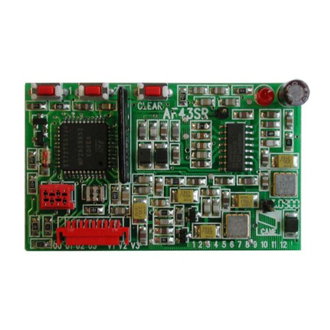
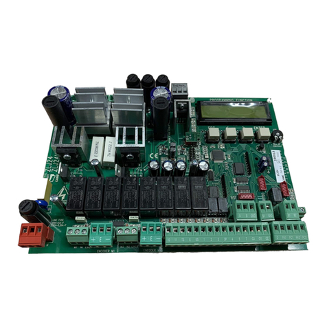
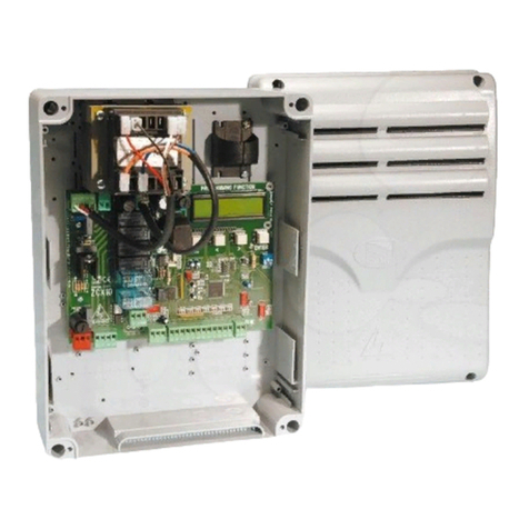
Scheda ingressi/uscite.
Descrizione delle parti
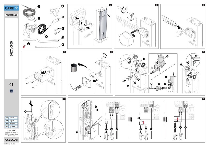
1Scheda I/O RS485
2Staffa supporto scheda I/O
3Staffa DIN
4Scheda gestione funzioni (RSE)
5Cavo interfaccia I/O
6Vite a testa esagonale M6x12
7Dado M6
8Vite autofilettante 3,9x13
9Rondella 4,3 x 12
Dati tecnici
MODELLI 806SA-0160
Alimentazione (V - 50/60 Hz) 24 AC/DC
Potenza (W) 3
Temperatura d’esercizio (°C) -20 ÷ +55
Grado di protezione (IP) 30
Collegamenti elettrici E
①Cavo grigio
②Cavo nero
③Cavo marrone
④Cavo bianco
Settaggi G
Sulla scheda elettronica, impostare la funzione F49 con rE2 = 5 (I/O - RS485).
Funzione degli ingressi e uscite della scheda I/O H
AIngresso per il collegamento di un pulsante con funzione SOLO APRE (COM-N1)
BIngresso per il collegamento di un pulsante con funzione SOLO CHIUDE (COM-N2)
CUscita contatto segnalazione rilevazione ostacolo
DUscita contatto segnalazione asta a finecorsa apre
EUscita contatto segnalazione asta a finecorsa chiude
FUscita contatto segnalazione sportello di ispezione aperto o motoriduttore sbloccato
o caduta asta (in caso di barriera munita di attacco asta sganciabile)
GUscita contatto segnalazione dello stato dell'ingresso CX
Ogni uscita è un contatto pulito (NO) con portata massima 1A – 24 V DC.
ENGLISH
Read the instructions carefully before beginning the installation and carry out
the procedures as specified by the manufacturer. • Only use this product for its
intended purpose. Any other use is hazardous. • The manufacturer cannot be
held liable for any damage caused by improper, unreasonable or erroneous use. •
Before connecting up the electrics, disconnect the power supply and any batteries.
• The device must be installed, wired, connected and tested according to good
professional practice, in compliance with the standards and laws in force. • This
product complies with current applicable reference standards.
Dismantling and disposal
Dispose of the packaging and the device responsibly at the end of its life cycle, in
compliance with the laws in force in the country where the product is used. The
recyclable components are marked with a symbol and the material ID marker.
THE DATA AND INFORMATION IN THIS MANUAL MAY BE CHANGED AT ANY TIME AND
WITHOUT NOTICE.
THE MEASUREMENTS, UNLESS OTHERWISE STATED, ARE IN MILLIMETRES.
Description
Input/output board.
Description of parts
1I/O board RS485
2I/O board support bracket
3DIN bracket
4Function control board (RSE)
5I/O interface cable
6Hex-head screw M6x12
7M6 nut
8Self-tapping screw 3.9x13
9Washer 4.3 x 12
Technical data
MODELS 806SA-0160
Power supply (V - 50/60 Hz) 24 AC/DC
Power (W) 3
Operating temperature (°C) -20 ÷ +55
Protection rating (IP) 30
Electrical connections E
①Grey cable
②Black cable
③Brown cable
④White cable
Settings G
On the electronic board, set function F49 with rE2 = 5 (I/O - RS485).
I/O board input and outboard functions H
AInput for connecting a button with OPEN ONLY function (COM-N1)
BInput for connecting a button with CLOSE ONLY function (COM-N2)
CContact output indicating obstacle detection
DContact output indicating open boom at limit switch
EContact output indicating close boom at limit switch
FContact output indicating inspection hatch open or gearmotor unlocked or boom
drop-away (where the barrier has a detachable boom attachment)
GContact output indicating CX input status
Each output is a dry contact (NO) with maximum capacity 1A – 24 V DC.
FRANÇAIS
Lire attentivement les instructions avant de commencer l'installation et d'effectuer
les interventions comme indiqué par le fabricant. • Ce produit ne devra être destiné
qu'à l'utilisation pour laquelle il a été expressément conçu et toute autre utilisation
est à considérer comme dangereuse. • Le fabricant décline toute responsabilité en
cas d’éventuels dommages provoqués par des utilisations impropres, incorrectes
et déraisonnables. • Avant d'effectuer les branchements électriques, mettre hors
tension et déconnecter les éventuelles batteries. • La position des câbles, la pose, la
connexion et l'essai doivent être réalisés selon les règles de l'art et conformément
aux normes et lois en vigueur. • Ce produit est conforme aux directives de référence
en vigueur.
Mise au rebut et élimination
Ne pas jeter l'emballage et le dispositif dans la nature au terme du cycle de vie de ce
dernier, mais les éliminer selon les normes en vigueur dans le pays où le produit est
utilisé. Le symbole et le sigle du matériau figurent sur les composants recyclables.
LE CONTENU DE CE MANUEL EST SUSCEPTIBLE DE SUBIR DES MODIFICATIONS À
TOUT MOMENT ET SANS AUCUN PRÉAVIS.
LES DIMENSIONS SONT EXPRIMÉES EN MILLIMÈTRES, SAUF INDICATION CONTRAIRE.
Description
Carte entrées/sorties.
Description des parties
1Carte E/S RS485
2Patte de support de la carte E/S
3Étrier DIN
4Carte de gestion des fonctions (RSE)
5Câble interface E/S
6Vis à tête hexagonale M6x12
7Écrou M6
8Vis autotaraudeuse 3,9x13
9Rondelle 4,3 x 12
Données techniques
MODÈLES 806SA-0160
Alimentation (V - 50/60 Hz) 24 AC/DC
Puissance (W) 3
Température de fonctionnement (°C) -20 ÷ +55
Degré de protection (IP) 30
Branchements électriques E
①Câble gris
②Câble noir
③Câble marron
④Câble blanc
Réglages G
Sur la carte électronique, configurer la fonction F49 avec rE2 = 5 (E/S - RS485).
Fonction des entrées et des sorties de la carte E/S H
AEntrée pour la connexion d’un bouton avec fonction OUVERTURE SEULEMENT
(COM-N1)
BEntrée pour la connexion d’un bouton avec fonction FERMETURE SEULEMENT
(COM-N2)
CSortie contact signalisation détection obstacle
DSortie contact signalisation lisse ouverte en fin de course
ESortie contact signalisation lisse fermée en fin de course
FSortie contact signalisation porte de visite ouverte, motoréducteur débloqué ou chute
de la lisse (en cas de barrière avec fixation de lisse détachable)
GSortie contact signalisation de l’état de l’entrée CX
Chaque sortie est un contact sec (NO) avec portée maximale 1 A – 24 VDC
РУССКИЙ
Внимательно прочитайте инструкции, прежде чем приступить к установке и
выполнению работ, согласно указаниям фирмы-изготовителя. • Это изделие
должно использоваться исключительно по назначению. Использование не по
назначению считается опасным. • Производитель не несет ответственности
за ущерб в результате неправильного, ошибочного или небрежного
использования изделия. • Перед выполнением электрических подключений
отключите электропитание и отсоедините аккумуляторы при их наличии. •
Монтаж, прокладка кабелей, электрические подключения и наладка системы
должны выполняться в соответствии с установленными правилами, мерами
безопасности и соответствующими процедурами эксплуатации. • Изделие
соответствует требованиям применяемых действующих директив.
Утилизация
Не выбрасывайте упаковку и устройство совместно с бытовыми отходами.
Утилизируйте их в соответствии с требованиями законодательства, действующего
в стране установки изделия. Пригодные для повторного использования
компоненты отмечены специальным символом с обозначением материала.
СОДЕРЖАНИЕ ЭТОГО РУКОВОДСТВА МОЖЕТ БЫТЬ ИЗМЕНЕНО В ЛЮБОЕ ВРЕМЯ
БЕЗ ПРЕДВАРИТЕЛЬНОГО УВЕДОМЛЕНИЯ.
ВСЕ РАЗМЕРЫ ПРИВЕДЕНЫ В МИЛЛИМЕТРАХ, ЕСЛИ НЕ УКАЗАНО ИНОЕ.
Описание
Плата ввода/вывода.
Описание компонентов
1Плата ввода/вывода с интерфейсом RS485
2Кронштейн крепления платы ввода/вывода
3DIN-рейка
4Плата управления функциями (RSE)
5Интерфейсный кабель ввода/вывода
6Винт с шестигранной головкой M6x12
7Гайка M6
8Саморез 3,9x13
9Шайба 4,3 x 12
Технические характеристики
МОДЕЛИ 806SA-0160
Напряжение питания (В, 50/60 Гц) ~/=24В
Мощность (Вт) 3
Диапазон рабочих температур (°C) -20 ÷ +55
Класс защиты (IP) 30
Электрические подключения E
①Серый провод
②Черный кабель
③Коричневый провод
④Белый провод
Настройки G
Установите на плате функцию F49 с rE2 = 5 (I/O - RS485).
Функция входов и выходов платы ввода/вывода H
AВход для подключения кнопки с функцией «ТОЛЬКО ОТКРЫТЬ» (COM-N1)
BВход для подключения кнопки с функцией «ТОЛЬКО ЗАКРЫТЬ» (COM-N2)
CВыход контакта индикации обнаружения препятствия
DВыход контакта индикации стрелы в крайнем положении открывания
EВыход контакта индикации стрелы в крайнем положении закрывания
FВыход контакта для сигнализации открытия смотровой дверцы, разблокировки
привода или падения стрелы (если шлагбаум оснащен системой защиты стрелы
от удара автомобиля)
GВыход контакта для сигнализации о состоянии входа CX
Каждый выход представляет собой чистый контакт (Н.Р.) с максимальной
нагрузкой 1 A =24 В.
FA01583M4A - 05/2021
