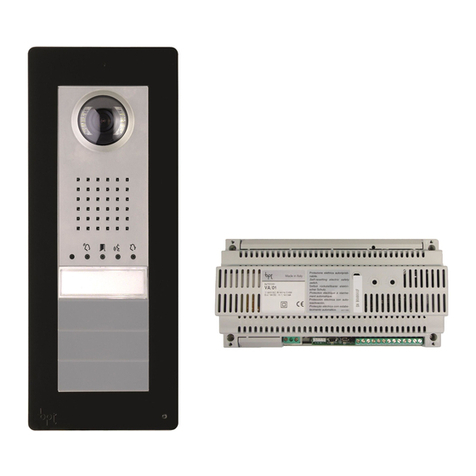
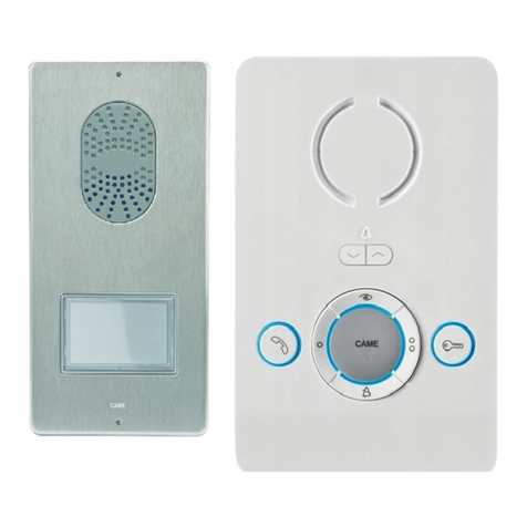
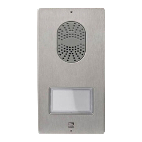
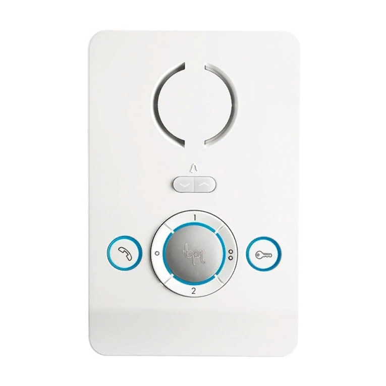
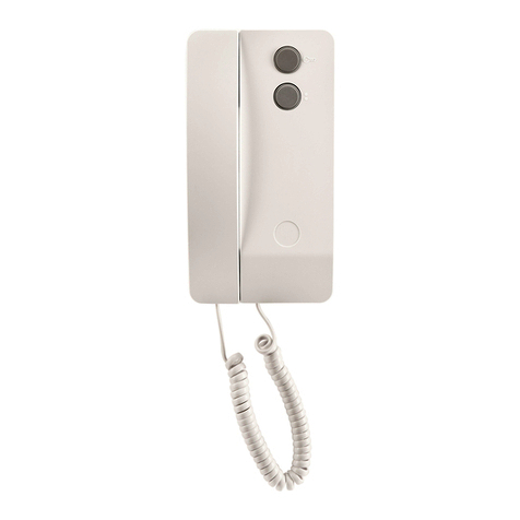
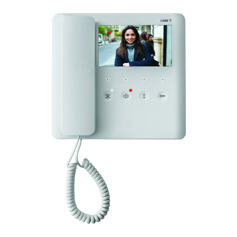
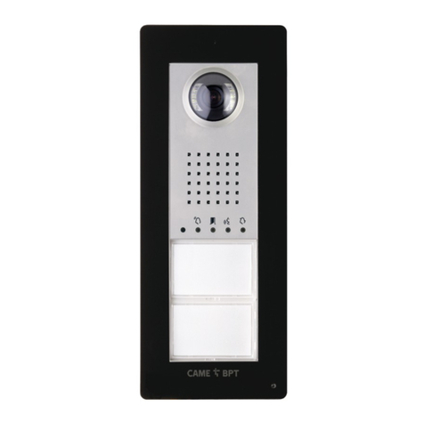
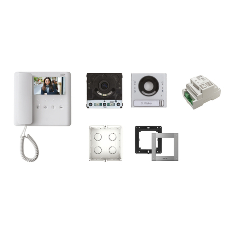
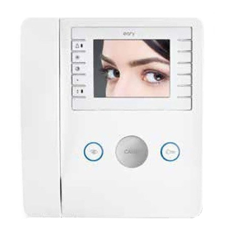
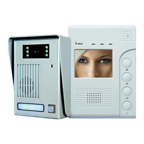
CAME PLACO-VC User manual

PLACO-VC
001CK0002
BIANCA-VC
24804662/18-09-2012
NL
Installatiehandleiding
PT
Manual de instalação
ES
Manual de Instalación
Manuel d’Installation FR
DE
Handbuch für den Installateur
EN
Installation Manual
IT
Manuale d’Installazione

2
135
99 30
3.5
6.5
243
207
135
99 30
3.5
6.5
243
207
IT
Avvertenze generali
All'apertura dell'imballo
• Leggereattentamenteleistruzioni,primadiiniziarel’installazioneedeseguiregliinterventicomespecicatodalcostruttore;
• Dopoavertoltol’imballaggioassicurarsidell’integritàdell’apparecchio;
• Glielementidell’imballaggio(sacchettiinplastica,polistiroloespanso,ecc.)nondevonoesserelasciatiallaportatadeibambiniinquantopotenzialifontidipericolo;
Indicazioni generali per l'installazione
• L’installazione,laprogrammazione,lamessainservizioelamanutenzionedelprodottodeveessereeettuatasoltantodapersonaletecnicoqualicatoedopportu-
namenteaddestratonelrispettodellenormativevigentiivicompreseleosservanzesullaprevenzioneinfortuni;
• Operareinambientisucientementeilluminatieidoneiperlasaluteeutilizzarestrumenti,utensiliedattrezzatureinbuonostato;
• IldispositivovainstallatoconformementealgradoIPindicatonellecaratteristichetecniche;
• Sesonoprevisti,nonostruireleapertureoiforidiventilazioneoperl’eliminazionedelcalore;
Collegamento elettrico dei dispositivi
• L’impiantoelettricodovràessererealizzatoinconformitàconlenormativeinvigorenelpaesediinstallazione;
• Primadicollegaregliapparecchi,controllarecheleindicazioniriportatesullapiastracorrispondanoaquelledellareteelettrica;
• Proteggeregliapparecchialimentaticontensionediretemedianteuninterruttoredireteonnipolareconunaseparazionedeicontattidialmeno3mm;
• Iconduttorideicablagginonutilizzatidevonoessereisolati.
• Perevitareicontattiaccidentali,stringereseparatamenteicavidicollegamentoallareteequellideisegnaliabassissimatensione.
• Saldarelegiunzionielaparteterminaledeiliondeevitaremalfunzionamenticausatidall’ossidazionedeglistessi;
Installazione conclusa
• Alterminedell’installazione,vericaresempreilcorrettofunzionamentodell’apparecchiaturaedell’impiantonelsuoinsieme;
• L’installatoredevecontrollarecheleinformazioniutiliall’utentesianopresentievenganoconsegnate;
Manutenzione
• Primadieettuarequalunqueoperazionedipuliziaodimanutenzione,toglierel'alimentazionealdispositivo;incasodiapparecchialimentaticontensionedirete,
interromperel’alimentazioneaprendol’interruttorechesitrovaamontediquesti;
• Incasodiguastoe/ocattivofunzionamentodiundispositivo,distaccarlodall’alimentazioneenontentarenessunariparazione;
• Perl’eventualeriparazionerivolgersisolamenteaduncentrodiassistenzatecnicaautorizzatodalcostruttoreecomunqueutilizzaresempreiricambifornitidaCAME
S.p.A.
Gli apparecchi dovranno essere destinati unicamente all'uso per il quale sono stati espressamente concepiti.
Il mancato rispetto delle prescrizioni sopra elencate può compromettere la sicurezza dell’apparecchio.
Il costruttore non può comunque essere considerato responsabile per eventuali danni derivanti da usi impropri, erronei ed irragionevoli.
SMALTIMENTO
Assicurarsicheilmaterialed’imballaggiononvengadispersonell’ambiente,masmaltitoseguendolenormevigentinelpaesediutilizzodelprodotto.
Allanedelciclodivitadell’apparecchioevitarechelostessovengadispersonell’ambiente.
Losmaltimentodell’apparecchiaturadeveessereeettuatorispettandolenormevigentieprivilegiandoilriciclaggiodellesueparticostituenti.
Suicomponenti,percuièprevistolosmaltimentoconriciclaggio,sonoriportatiilsimboloelasigladelmateriale.
NOTE AGGIUNTIVE - VERSIONI SPECIALI PER AUDIOLESI
IdispositiviintegranounsistemadispirediinduzionecompatibileconleprotesiacusticheinposizioneT(ETS300381,EN60118).
mImportante!
Pertuttelealtreinformazioniecaratteristichetecnichedeidispositivi,fareriferimentoalleistruzioniallegatealprodotto.
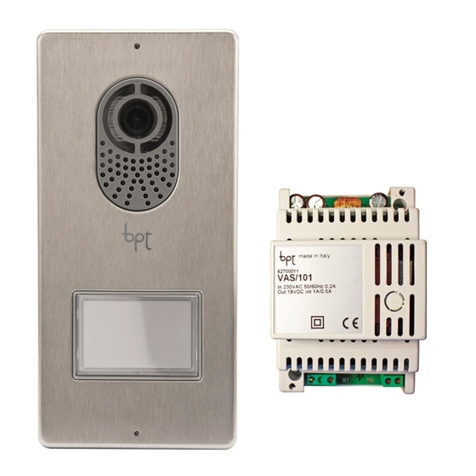
Postoesternodivideocito-
fonia
Alimentazione
Videoterminale
Chiaveabrugola
2Tassellie
2viticonrosetta
Contenuto dell'imballo
ACCESSORI (da comandare separatamente)
Dimensioni
DPS Pulsantesingolo
DPH Pulsantesingoloealtezzadoppia
DPD Pulsantedoppio
LTP Tettucciodaparete LSI Scatoladaincasso
LCI Cornicedaincasso
3
1
2
1
2
– +
AL B
M/S
CL.RES
IT
Installazione
Sganciarel’apparecchiodalsupportometallico,facendoloscorreresudiessodopoaverpremutoilpulsante
plastico(gura1).
Fissareilsupportometallicoallascatolad’incassotondaØ60mm(gura2)oppureallascatolarettangolare
503(gura3-4)utilizzandolevitiindotazioneerispettandol’indicazioneUP .
Lascatoladeveessereinstallataaun'altezzaadeguataperl'installatore.Evitareilserraggioeccessivodelleviti.
Eettuatiicollegamenti,agganciareilvideoterminalealsupportometallico(gura5-6).
Persganciarel’apparecchiodalsupportometallicopremereilgancioplasticoesollevareilterminale(gura7).
M1
AL Ingressoallarme(1)
–
+
Chiamatapianerottolo
BIngressolineaBUS(nonpolarizzato)
(1)Funzioneaccessibileesclusivamentese1posto
diportineriaèintegratonell’impianto
Caratteristiche tecniche
Alimentazione da BUS: 15÷20VDC
Assorbimento: 200mAmax(<1mAstand-by)
Assorbimento singolo LED (
panico, Esclusione
suoneria): 1mA
Dimensioni: 170x145x30,9mm
Temperatura di stoccaggio: -25°C+70°C
Temperatura d'esercizio: 0°C+35°C
Grado di protezione IP: IP20
Standard video: PAL/NTSC
Display: LCDTFTacolorida3,5”
Morsettiere
1
234
7
6
5
BIANCAVC

4
43,5
45
7,5 57
70
106
A
B
64,5
70
145
A
B
500 mm
1080 mm
77°
94°
800 mm
500 mm
163,5 mm
43,5 mm
H= 165 cm
(HAUTEUR
CONSEILLÉ)
500 mm
1080 mm
77°
94°
800 mm
500 mm
163,5 mm
43,5 mm
M2M1
+–
IT
Caratteristiche tecniche
Alimentazione: 230VAC50÷60Hz
Corrente assorbita: Imax
200mA
AC
AC
Potenza dissipata: 10Wmax
Alimentazione nominale: 18VDC1A-0,5A1’/3’
Dimensioni: 4DIN
Temperatura di stoccaggio: -25°C+70°C
Temperatura d'esercizio: 0°C+35°C
Grado di protezione IP: IP30
Installazione a parete
Tramitelachiaveabrugola,svitarelevitidibloccaggioetoglierelaplacca(gura1).Fissareitasselliindota-
zioneeavvitareilpostoesterno(gura2-)all'altezzadesideratatenendocontodelposizionamentodell'obiet-
tivodellatelecamera(gura3).
Farpassarelaguainaconiconduttorid'impiantocomeindicatoingura2.Estrarreilcoprimorsettoinplastica
edeettuareicollegamenti(gura4).
Unavoltaterminatiicollegamentireinserireicoprimorsetti.Montarelaplaccafrontale(gura1).
Installazione a incasso
Murarelascatolad’incassoall’altezzadesideratatenendocontodelposizionamentodell’obiettivodellatele-
camera(gura3)efacendopreventivamentepassarelatubazioneconiconduttorid’impiantoattraversouno
deipuntiarottura(gura5puntoA).
Nellamessainoperadellascatolad’incassosipotrannoevitarepossibilideformazioniutilizzandol’apposito
distanzialeindotazione(gura5puntoB).
Conunachiaveabrugola,svitarelevitidibloccaggioetoglierelaplaccadelpostoesterno(gura1).
Introdurreicavidicollegamentonell'appositoforo(gura2),ssareilpostoesternosullacornicecomeindi-
catoingura6;estrarreilcoprimorsettoinplasticaedeettuareicollegamenti(gura4).Unavoltaterminati
icollegamentireinserireicoprimorsetti.
Montarelaplaccafrontale(gura1).
1
Installazione
L’alimentazione deve SEMPRE essere installata in verticale.
L’apparecchioèinstallabilesuguidaDIN(EN50022)inunappositoquadroelettrico.
Perledimensionidiingombrovederelag.1.
Prevedere una ventilazione sufficiente nel caso in cui l’alimentazione venga installata in un conte-
nitore.
Morsettiere
M1
~Rete230V
~
M2
–
+Alimentazione18VDC(*)
(*)L’apparecchiaturaèprotettacontroisovrac-
carichieicorto-circuiti.
H=165cm
(ALTEZZA
CONSIGLIATA)
1
2
5
6
3
4
VAS/101CM
PLACOVC

5
M1
BOUT
M2
SW3
PROG
RESET
PROG
M2M1
+–
VLS/300
B
B
NO
C
–+
NO
C
M1
BOUT
M2
SW3
PROG RESET
PROG
IT
Caratteristiche tecniche
Posto esterno
Alimentazione: 16-18VDC
Assorbimento: 250mA(100mAstand-by)
Dimensioni: 99x207x30mm
Temperatura di stoccaggio: -25°C+70°C
Temperatura d'esercizio: -15°C+50°C
Grado di protezione IP: IP54
Telecamera
Standard video: PAL/NTSC
Risoluzione: 680x512pixel
Illuminazione minima: 1LUX
VAS/101-CM
OPZIONE:
Modulo bus
2 uscite ausiliarie
Relè 1
Relè 2
Morsettiera
M1
BOUT Bus
(nonpolarizzato)
+Alimentazione
16-18VDC
–
M2
–Massa
Pulsante
apriporta(NO)
Elettroserratura
12V1Amax
–
Funzioni delle morsettiere
Regolazioni
audioaltoparlante
audiomicrofono
elttroserratura1÷10s.default1s
Ingresso in Programmazione.Premere5volteilpulsante entro5s.Unbrevesegnaleacusticoconferma
l’ingressoinprogrammazionea.
Programmazione della melodia associata alla chiamata dal posto esterno (1 segnale acustico).peras-
coltarelemelodieinsequenza,premereilpulsante b.Perselezionarelamelodiaedusciredallaprogram-
mazionepremereiltasto c.Perselezionarelamelodiaeproseguireconlaprogrammazionepremereil
tasto d.
Programmazione della melodia associata alla chiamata dal pianerottolo (2 segnali acustici).Perquesto
tipodiprogrammazioneb c dprocederecomela“Programmazionedellamelodiaassociataallachiamata
dalpostoesterno”precedentementedescritta.
Programmazione del numero di squilli di chiamata (3 segnali acustici). Premere iltasto tantevolte
quantisonoglisquillichesièsceltoperlachiamata(da1a6squilli) e.3sdall’ultimapressionedeltastoverrà
riprodottalachiamataselezionataperilnumerodisquilliprescelto.Perselezionarelamelodiaedusciredalla
programmazionepremereiltasto f.
Programmazione
yPer la programmazione della chiamata, vedere la documentazione dei posti esterni.
a
b
c
de f
X 5
beep

6
CL.RES CL.RES CL.RES
1 2 3
XDV/304
MASTER SLAVE
M/S M/S
VAS/101
2
2
2
VAS/101
2
N° MASTER
N° SLAVE
VAS/101
XDV/304
IT
Distanza
Esempi di collegamento
N° MASTER
MAX
N° SLAVE
MAX
2x1 mm23 5
UTP/CAT5 1 2
Distanze
2x1 mm2UTP/CAT 5 2x2,5mm2
La+Lb ≤100m ≤100m –
Lc ≤25m –≤60m
Ponte di resistenza di fine bus: Ponte di selezione Master/Slave
In caso di chiamata su
più monitor in parallelo,
suoneranno tutti; ma il
video verrà attivato solo
nei derivati configurati
come Master
100 m max
2x1mm2
A scacchiera
monitor
AB
La
Lb
Lc

7
PLACO-VC
VAS/101
A
+
–
M2
-
-
1.1
BIANCA-VC
M1
AL
B
–
+
CL RES M/S
1.3
BIANCA-VC
M1
AL
B
–
+
CL RES M/S
1.2
BIANCA-VC
M1
AL
B
–
+
CL RES M/S
+
BOUT
-
M1
Automatisme
CAME
Relais
12Vcc
M2
230 V
PLACO-VC
Automatisme
CAME
Relais
12Vcc
+
BOUT
-
-
-
+
–
M2
VAS/101
A
230 V
CL RES M/S
M1
AL
B
–
+
BIANCA-VC
M2
M1
IT
A
B

2
135
99 30
3.5
6.5
243
207
135
99 30
3.5
6.5
243
207
EN
General warnings
On opening the pack
• Readtheinstructionscarefullybeforestartinginstallationandproceedasspeciedbythemanufacturer;
• Afterremovingthepackaging,checktheconditionoftheunit;
• Thepackagingitems(plasticbags,polystyrenefoametc.)mustnotbehandledbychildrenastheymaybedangerous;
General installation instructions
• Installation,programming,commissioningandmaintenanceoftheproductmustonlybeperformedbyqualiedtechnicianswhohavebeenproperlytrainedin
compliancewithcurrentstandards,includinghealthandsafetyregulations;
• Operateinsucientlylitareasthatareconducivetohealthandusetools,utensilsandequipmentthatareingoodworkingorder;
• ThedevicemustbeinstalledinaccordancewiththeIPdegreeindicatedinthetechnicalfeatures;
• Ifpresent,donotobstructtheopeningsorventilation/heatdispersingholes;
Wiring the devices
• Theelectricalsystemmustcomplywithcurrentstandardsinthecountryofinstallation;
• Beforeconnectingtheunits,checkthattheindicationsontheplatecorrespondwiththoseofthemains;
• Protectunitspoweredwithmainsvoltageusingasinglepolemainsswitchwithcontactseparationofatleast3mm;
• Wiresbelongingtocablesthatarenotusedmustbeinsulated.
• Topreventaccidentalcontact,tightenthemainsconnectioncablesandthosefortheverylowvoltagesignalsseparately.
• Weldthejointsandtheendsofthewirestopreventmalfunctionscausedbywireoxidation;
Installation completed
• Wheninstallationiscompleted,alwayscheckforcorrectoperationoftheunitandthesystemasawhole;
• Theinstallermustcheckthattheinformationrequiredbytheuserispresentandhandedover;
Maintenance
• Beforeperforminganycleaningormaintenanceoperation,disconnectthepowersupplytothedevice.Iftheunitsaremains-powered,disconnectthepowerusing
theswitchupstreamfromtheunits;
• Inthecaseofdevicefailureormalfunction,disconnectitfromthepowersupplyanddonottamperwithit;
• Shouldtheunitbeinneedofrepair,contactonlyatechnicalsupportcentreauthorisedbythemanufacturerandalwaysusesparepartsprovidedbyCAMES.p.A.
The units must only be used for the purpose for which they were explicitly designed.
Failure to follow the instructions provided above may compromise the unit’s safety.
The manufacturer declines all liability for any damage as a result of improper, incorrect or unreasonable use.
DISPOSAL
Donotlittertheenvironmentwithpackingmaterial:makesureitisdisposedofaccordingtotheregulationsinforceinthecountrywheretheproductisused.
Whentheequipmentreachestheendofitslifecycle,takemeasurestoensureitisnotdiscardedintheenvironment.
Theequipmentmustbedisposedofincompliancewiththeregulationsinforce,recyclingitscomponentpartswhereverpossible.
Componentsthatqualifyasrecyclablewastefeaturetherelevantsymbolandthematerial’sabbreviation.
ADDITIONAL NOTES - SPECIAL VERSIONS FOR THE HEARING-IMPAIRED
ThedevicesfeatureaninductionloopsystemcompatiblewithhearingaidsintheTposition(ETS300381,EN60118).
mImportant!
Forallotherinformationandtechnicalfeaturesofthedevices,refertotheinstructionsenclosedwiththeproduct.
Videoentrycontrol
Powersupply
Videoentryphone
Allenwrench
2plugsand
2screwswithwasher
Packaging contents
ACCESSORIES (can be purchased separately)
Dimensions
DPS Singlebutton
DPH Singlebuttonanddoubleheight
DPD Doublebutton
LTP Wallroof LSI Recessedbox
LCI Recessedframe

3
1
2
1
2
– +
AL B
M/S
CL.RES
EN
Installation
Removetheunitfromthemetalsupportbyslidingitafterpressingtheplasticbutton(gure1).
Fastenthemetalsupporttotheroundbuilt-inboxofØ60mm(gure2)ortotherectangularbox503(gure
3-4)usingtheprovidedscrewsandobservingtheUPindication .
Theboxmustbettedatasuitableheightinrelationtotheinstaller.Avoidexcessivetighteningofthescrews.
Oncetheconnectionshavebeenmade,attachthevideoterminaltothemetalsupport(gure5-6).
Toreleasetheunitfromthemetalsupport,presstheplastichookandlifttheterminal(gure7).
M1
AL Alarminput(1)
–
+
Doorbell
BBUSlineinput(notpolarised)
(1)Functiononlyaccessibleifthesystemfeatures
1porterstation
Technical features
Power supply from BUS: 15-20VDC
Absorption: 200mAmax(<1mAstand-by)
Single LED absorption (panic, Ring disabled):
1mA
Dimensions: 170x145x30.9mm
Storage temperature: -25°C+70°C
Operating temperature: 0°C+35°C
IP degree: IP20
Standard video: PAL/NTSC
Display: LCDTFTcolour3.5”
Terminal boards
1
234
7
6
5
BIANCAVC

4
43,5
45
7,5 57
70
106
A
B
64,5
70
145
A
B
500 mm
1080 mm
77°
94°
800 mm
500 mm
163,5 mm
43,5 mm
H= 165 cm
(HAUTEUR
CONSEILLÉ)
500 mm
1080 mm
77°
94°
800 mm
500 mm
163,5 mm
43,5 mm
M2M1
+–
EN
1
Technical features
Power supply: 230VAC50-60Hz
Current absorbed Imax
200mA
AC
AC
Power dissipated: 10Wmax
Rated power supply: 18VDC1A-0.5A1’/3’
Dimensions: 4DIN
Storage temperature: -25°C+70°C
Operating temperature: 0°C+35°C
IP degree: IP30
Wall mounting
WiththeAllenwrench,unscrewtheblockingscrewsandremovetheplate(gure1).Fixthegivenplugsand
screwthe entrypanel(gure2-) atthe desiredheightconsideringthepositionofthe lensof thecamera
(gure3).
Runthesheathwiththesystemconductorsasshowningure2.Extracttheplasticterminalcoverandwire
theconnections(gure4).
Oncealltheconnectionshavebeenmade,re-inserttheterminalcovers.Installthefrontplate(gure1).
Recessed installation
Installtherecessedboxatthedesiredheightconsideringthepositionofthelensofthecamera(gure3),but
inadvance,runthehosewiththesystemconductorsthroughoneofthebreakingpoints(gure5pointA).
Duringinstallationoftherecessedboxitispossibletoavoidanydeformationbyusingtheprovidedspacer
(gure5pointB).
WiththeAllenwrench,unscrewtheblockingscrewsandremovetheentrypanelplate(gure1).
Introducethecableconnectionsinthespecialhole(gure2)andxtheentrypanelontheframeasshownin
gure6;extracttheplasticterminalcoverandwiretheconnections(gure4).Oncealltheconnectionshave
beenmade,re-inserttheterminalcovers.
Installthefrontplate(gure1).
1
Installation
The power supply must ALWAYS be installed vertically.
TheunitcanbeinstalledonaDINguide(EN50022)inaspecialelectricalpanel.
Fortheoveralldimensions,seeg.1.
Provide sufficient ventilation if the power supply is installed in a container.
Terminal boards
M1
~230Vmains
~
M2
–
+18VDCpowersupply(*)
(*)Theunitisprotectedagainstoverloadsand
shortcircuits.
H=165cm
(RECOMMENDED
HEIGHT)
1
2
5
6
3
4
VAS/101CM
PLACOVC

5
M1
BOUT
M2
SW3
PROG
RESET
PROG
M2M1
+–
VLS/300
B
B
NO
C
–+
NO
C
M1
BOUT
M2
SW3
PROG RESET
PROG
EN
VAS/101-CM
Technical features
Entry panel
Power supply: 16-18VDC
Absorption: 250mAmax(100mAstand-by)
Dimensions: 99x207x30mm
Storage temperature: -25°C+70°C
Operating temperature: -15°C+50°C
IP degree: IP54
Video camera
Standard video: PAL/NTSC
Resolution: 680x512pixels
Minimum lighting: 1LUX
OPTIONAL:
Bus module
2 auxiliary exits
Relay 1
Relay 2
Terminal board
M1
BOUT Bus
(notpolarised)
+Powersupply
16-18VDC
–
M2
–Earth
Doorrelease
button(NO)
Electriclock
12V1Amax
–
Functions of the terminal boards
Adjustments
speakaudio
microphoneaudio
electriclock1-10s.default1s
Accessing programmingPressthebutton vetimeswithin5s.Abriefacousticsignalwillconrmthat
programminghasbeenaccesseda.
Programming the melody associated to the call from the entry panel (1 acoustic signal).Tohearthe
melodiesinsequence,pressthebutton b.Toselectthemelodyandexitprogramming,pressthebutton
c.Toselectthemelodyandcontinuewithprogramming,pressthebutton d.
Programming the melody associated with the doorbell (2 acoustic signals).Forthistypeofprogram-
mingb c dproceedaspreviouslydescribedfor“Programmingthemelodyassociatedtothecallfromthe
entrypanel”.
Programming the number of call rings (3 acoustic signals). pressthebutton thenumberoftimesequal
tothenumberofringsselectedforthecall(from1to6rings) e.3safterthebuttonispressedthelasttime,
thecallselectedfortheselectednumberofringswillbewillbereproduced.Toselectthemelodyandexit
programming,pressthebutton f.
Programming
yFor call programming, see the entry panel documentation.
a
b
c
de f
X 5
beep

6
CL.RES CL.RES CL.RES
1 2 3
XDV/304
MASTER SLAVE
M/S M/S
VAS/101
2
2
2
VAS/101
2
N° MASTER
N° SLAVE
VAS/101
XDV/304
EN
Demier
moniteur
Distances
Connection examples
MAX N°
MASTERS
MAX N°
SLAVES
2x1 mm23 5
UTP/CAT5 1 2
Distances
2x1 mm2UTP/CAT 5 2x2.5
mm2
La+Lb ≤100m ≤100m –
Lc ≤25m –≤60m
Bus end resistance jumper: Master/slave selection jumper
If multiple monitors are
called in parallel, they
will all ring, but the
video will only be acti-
vated in the receivers
configured as Masters
100 m max
2x1 mm2
Last
monitor
AB
La
Lb
Lc

7
PLACO-VC
VAS/101
A
+
–
M2
-
-
1.1
BIANCA-VC
M1
AL
B
–
+
CL RES M/S
1.3
BIANCA-VC
M1
AL
B
–
+
CL RES M/S
1.2
BIANCA-VC
M1
AL
B
–
+
CL RES M/S
+
BOUT
-
M1
Automatisme
CAME
Relais
12Vcc
M2
230 V
PLACO-VC
Automatisme
CAME
Relais
12Vcc
+
BOUT
-
-
-
+
–
M2
VAS/101
A
230 V
CL RES M/S
M1
AL
B
–
+
BIANCA-VC
M2
M1
EN
A
B

2
135
99 30
3.5
6.5
243
207
135
99 30
3.5
6.5
243
207
DE
Allgemeine Hinweise
Bei Öffnen der Verpackung
• VorderMontagedieAnleitungaufmerksamdurchlesenundalleArbeiten,wievomHerstellerangegeben,ausführen;
• NachdemAuspackenüberprüfen,dassdasGerätunversehrtist;
• DieBestandteilederVerpackung(Plastiktüten,Polystyrolschaumusw.)müssenaußerhalbderReichweitevonKinderngehaltenwerden,dasiepotentielleGefahren-
quellendarstellen.
Allgemeine Montageanweisungen
• DieMontage,Programmierung,InbetriebnahmeundWartungdesProduktsdarfnurvonqualiziertenundentsprechendausgebildetenFachpersonalunterBeach-
tungdergeltendenSicherheitsbestimmungenundUnfallverhütungsmaßnahmendurchgeführtwerden;
• InausreichendbeleuchtetenundnichtgesundheitsschädigendenRäumenarbeitenundnurInstrumenteundWerkzeuge,dieingutemZustandsind,benutzen;
• DasGerätmussentsprechenddemindentechnischenDatenaufgeführtenIP-Schutzgradmontiertwerden;
• Wennvorgesehen,solltenÖnungenbzw.LüftungsschlitzezumAuskühlennichtverdecktwerden;
Elektrischer Anschluss der Geräte
• DieelektrischeAnlagemussdenimInstallationslandgeltendenSicherheitsnormenentsprechen;
• VordemAnschlussderGerätekontrollieren,dassdieaufdemTypenschildangegebenenDatendenendesNetzanschlussesentsprechen;
• DiemitNetzstromgespeistenGerätemiteinemomnipolarenSchutzschaltermiteinemAbstandvonmindestens3mmzwischendenKontakten,schützen;
• DienichtverwendetenSteckverbindungenisolieren.
• UmungewolltenKontaktenvorzubeugen,dieNetzkabelunddieNiederspannungs-Signalleitungengetrenntumbinden.
• DieAnschlussstellenunddieEndenderDrähteverschweißen,umStörungendurchOxidationderselbenzuvermeiden;
Montage abgeschlossen
• NachAbschlussderMontageimmerdenkorrektenBetriebdesGerätsunddergesamtenAnlageüberprüfen;
• DerMontagefachmannmussüberprüfen,dassdiebenutzerrelevantenAngabenvorhandensindunddemBenutzerausgehändigtwerden;
Wartung
• VorallenReinigungs-oderWartungsmaßnahmendenNetzsteckerausderDoseziehen;beimitNetzstromgespeistenGeräten,dieStromzufuhrdurchÖnendes
davorliegendenSchaltersunterbrechen;
• ImFalleinerStörungund/oderdesfehlerhaftenBetriebseinesGeräts,denNetzsteckerausderDoseziehenundkeineeigenständigenReparaturendurchführen;
• FüretwaigeReparaturenwendenSiesichausschließlichaneinevomHerstellergenehmigteKundendienststelle.InjedemFallimmervonderCAMES.p.A.gelieferte
Ersatzteileverwenden
Die Geräte dürfen nur für den Zweck, für den sie entwickelt wurden, verwendet werden.
Die Nichtbeachtung der oben aufgeführten Vorschriften kann die Sicherheit des Geräts beeinträchtigen.
Der Hersteller haftet nicht für Schäden, die durch den unsachgemäßen, falschen oder unvernünftigen Gebrauch verursacht werden.
Entsorgung
VergewissernSiesich,dassdasVerpackungsmaterialgemäßdenVorschriftendesBestimmungslandesordnungsgemäßundumweltgerechtentsorgtwird.
DasnichtmehrbenutzbareGerätmussumweltgerechtentsorgtwerdenunddarfnichtindieUmweltgelangen.DasGerätmussgemäßdengeltendenVorschriften
entsorgtwerden,dabeimussdasRecyclingderBestandteiledesGerätsbevorzugtwerden.
DiewiederverwertbarenBestandteiledesGeräts,sindmiteinemSymbolunddemMaterial-Kürzelgekennzeichnet.
ZUSÄTZLICHE HINWEISE - SPEZIALMODELLE FÜR HÖRGESCHÄDIGTE
IndenGerätensindInduktionsschleifenintegriert,diemitHörgeräteninderStellungT(ETS300381,EN60118)kompatibelsind.
mWichtig!
AlleweiterenAngabenundtechnischenDatenderGerätendenSieinden,demProduktbeigefügtenAnleitungen.
AußenstationVideosprechanlage
Vorschaltgerät
Video-Gegensprechanlage
Inbusschlüssel
2Dübelund
2SchraubenmitUnterlegscheibe
Inhalt der Verpackung
ZUSATZTEILE (müssen getrennt erworben werden)
Maße
DPS Einfachtaster
DPH EinzeltasteunddoppelteHöhe
DPD Doppeltaste
(Ltp) ÜberdachungfürWandmontage LSI Unterputzschachtel
LCI Unterputzrahmen

3
1
2
1
2
– +
AL B
M/S
CL.RES DE
Montage
DasGerätausder Metallhalterungaushängen,dabeinachDruck aufdieKunststotasteaufder Halterung
verschieben(Abbildung1).
DieMetallhalterunganderUnterputzdoseØ60mm(Abbildung2)bzw.anderUnterputzschachtel503(Abbil-
dung3-4)befestigen,hierfürdiebeiliegendenSchraubenverwendenunddieAngabeUPbeachten .
DieSchachtelmussinfürdenMontagefachmanngeeigneterHöhemontiertwerden.DieSchraubennichtzu
starkanziehen.
NachVornahmederAnschlüsse,dasVideoterminalindieMetallhalterungeinhängen(Abbildung5-6).
UmdasGerätausderMetallhalterungauszurasten,denKunststohakendrückenunddasTerminalanheben
(Abbildung7).
M1
AL Alarmeingang(1)
–
+
AnrufvomTreppenhaus
B EingangBUS-Leitung(ungepolt)
(1)Funktionistnurdannfreigeschaltet,wennein
Pforten-PostenindieAnlageintegriertwurde
Technische Daten
Betriebsspannung über BUS: 15-20VDC
Stromaufnahme: 200mAmax(<1mAstand-by)
Stromaufnahme pro LED (Panik , Läutwerkabs-
chaltung): 1mA
Maße: 170x145x30,9mm
Lagertemperatur: -25°C+70°C
Betriebstemperatur: 0°C+35°C
Schutzart: IP20
Standardbildschirm: PAL/NTSC
Display: LCDTFTFarbdisplay3,5”
Klemmleisten
1
234
7
6
5
BIANCAVC

4
43,5
45
7,5 57
70
106
A
B
64,5
70
145
A
B
500 mm
1080 mm
77°
94°
800 mm
500 mm
163,5 mm
43,5 mm
H= 165 cm
(HAUTEUR
CONSEILLÉ)
500 mm
1080 mm
77°
94°
800 mm
500 mm
163,5 mm
43,5 mm
M2M1
+–
DE
Technische Daten
Betriebsspannung 230VAC50÷60Hz
Stromaufnahme: Imax.
200mA
AC
AC
Verlustleistung: max.10W
Nennspannung: 18VDC1A-0,5A1’/3’
Maße: 4DIN
Lagertemperatur: -25°C+70°C
Betriebstemperatur: 0°C+35°C
Schutzart: IP30
Aufputz-Montage
MitdemInbusschlüsseldieBefestigungsschraubenlösenunddieBlendeabnehmen(Abbildung1).Diemi-
tgeliefertenDübeleinsteckenunddieAußenstation(Abbildung2)unterBerücksichtigungderObjektivstel-
lungderTelekameraingewünschterHöheanschrauben(Abbildung3).
WieinAbbildung2dargestellt,denKabelschlauchmitdenAnlagenleiternhindurchführen.DieKunststo-
KlemmenabdeckungentfernenunddieAnschlüssevornehmen(Abbildung4).
NachVornahmederAnschlüsse,dieKlemmenabdeckungenwiedereinstecken.Frontblendemontieren(Ab-
bildung1).
Unterputz-Montage
Die Unterputzschachtel unter Berücksichtigung der Objektivstellung der Telekamera (Abbildung 3) in
gewünschterHöheeinbauen,zuvordieRohrleitungmitdenAnlagenleiterndurcheinesdervorgestanzten
Löcherführen(Abbildung5PunktA).
BeimEinsetzenderUnterputzschachtelkönnendurchVerwendungdesbeiliegendenAbstandshaltersVerfor-
mungenvermiedenwerden(Abbildung5PunktB).
MitdemInbusschlüsseldieBefestigungsschraubenlösenunddieBlendederAußenstationabnehmen(Ab-
bildung1).
DieAnschlusskabeldurchdieentsprechendeAussparungziehen(Abbildung2)unddieAußenstation,wiein
Abbildung6dargestellt,aufdemRahmenbefestigen;DieKunststo-Klemmenabdeckungentfernenunddie
Anschlüssevornehmen(Abbildung4). NachVornahmederAnschlüsse, dieKlemmenabdeckungen wieder
einstecken.Frontblendemontieren(Abbildung1).
1
Montage
Das Netzgerät muss IMMER senkrecht montiert werden.
DasGerätkannaufeinerDIN-Schiene(EN50022)ineinemdafürvorgesehenenSchaltschrankmontiertwer-
den.
FürdieAbmessungensiehedieAbbildung1.
Falls das Netzgerät in einem Gehäuse montiert wird, für ausreichende Belüftung sorgen.
Klemmleisten
M1
~Netzstrom230V
~
M2
–
+Betriebsspannung18VDC(*)
(*) Das Gerät ist vor Überlastungen und
Kurzschlüssenelektronischgeschützt.
H=165
(EMPFOHLENE
HÖHE)
1
2
5
6
3
4
VAS/101CM
PLACOVC

5
M1
BOUT
M2
SW3
PROG
RESET
PROG
M2M1
+–
VLS/300
B
B
NO
C
–+
NO
C
M1
BOUT
M2
SW3
PROG RESET
PROG
DE
Technische Daten
Außenstation
Betriebsspannung 16-18VDC
Stromaufnahme: 250mA(100mAstand-by)
Maße: 99x207x30mm
Lagertemperatur: -25°C+70°C
Betriebstemperatur: -15°C+50°C
Schutzart: IP54
Analogische
Standardbildschirm: PAL/NTSC
Lösung: 680x512pixel
Mindestbeleuchtung: 1LUX
OPTIONELL:
Bus-Modul
2 Neben-Outputs
Relais 1
Relais 2
Klemmleiste
M1
BOUT Bus
(ungepolt)
+Betriebsspan-
nung
16-18VDC
–
M2
–Masse
Taster
Türöner(NO)
Elektroschloss
12Vmax.1A
–
Belegung der Klemmleisten
Einstellungen
AudioLautsprecher
AudioMikrofon
Elektroschloss1÷10Sek.Default1Sek.
Zugang zur Programmierung.Innerhalbvon5Sek.5MaldenTaster drückenEinkurzerSignaltonbestä-
tigtdenEinstiegindieProgrammierunga.
Programmierung der dem Anruf durch die Außenstation zugeordneten Melodie (1 Signalton).Umdie
Melodiennacheinanderanzuhören,dieTaste bdrücken.UmdieMelodieauszuwählenundausderPro-
grammierungauszusteigen,dieTaste cdrücken.UmdieMelodieauszuwählenunddieProgrammierung
fortzuführen,dieTaste ddrücken.
Programmierung der einem Anruf vom Treppenhaus zugeordneten Melodie (2 Signaltöne). Fürdiese
Programmierungsweiseb c dwieinderzuvorbeschriebenen"ProgrammierungderdemAnrufdurchdie
AußenstationzugeordnetenMelodie"vorgehen.
Programmierung der Anzahl der Ruftöne (3 Signaltöne).DieTaste sooftdrücken,wiediefürdenAnruf
gewünschtenRuftöne(1bis6Ruftöne)e.3Sek.nachdemletztenTastendruckwirddergewählteAnrufmit
derAnzahlderfestgelegtenRuftönewiederholt.UmdieMelodieauszuwählenundausderProgrammierung
auszusteigendieTaste fdrücken.
Programmierung
yFür die Rufprogrammierung, siehe die Unterlagen der Außenstationen.
a
b
c
de f
X 5
beep

6
CL.RES CL.RES CL.RES
1 2 3
XDV/304
MASTER SLAVE
M/S M/S
VAS/101
2
2
2
VAS/101
2
N° MASTER
N° SLAVE
VAS/101
XDV/304
DE
Abstände
Anschlussbeispiele
MAX.
ANZAHL
MASTER
MAX.
ANZAHL
SLAVE
2x1 mm23 5
UTP/CAT5 1 2
Abstände
2x1 mm2UTP/CAT 5 2x2,5mm2
La+Lb ≤100m ≤100m –
Lc ≤25m –≤60m
Widerstands-Jumper für Bus-Ende: Jumper zur Auswahl Master/Slave
Bei Anruf auf mehreren
parallel geschalteten
Bildschirmen, läuten
alle; es wird jedoch nur
der Bildschirm von als
Master konfigurierten
Innensprechstellen ein-
geschaltet
max. 100 m
2x1mm2
Letzter
Bildschirm
AB
La
Lb
Lc

7
PLACO-VC
VAS/101
A
+
–
M2
-
-
1.1
BIANCA-VC
M1
AL
B
–
+
CL RES M/S
1.3
BIANCA-VC
M1
AL
B
–
+
CL RES M/S
1.2
BIANCA-VC
M1
AL
B
–
+
CL RES M/S
+
BOUT
-
M1
Automatisme
CAME
Relais
12Vcc
M2
230 V
PLACO-VC
Automatisme
CAME
Relais
12Vcc
+
BOUT
-
-
-
+
–
M2
VAS/101
A
230 V
CL RES M/S
M1
AL
B
–
+
BIANCA-VC
M2
M1
DE
A
B

2
135
99 30
3.5
6.5
243
207
135
99 30
3.5
6.5
243
207
FR
Avertissements généraux
Au moment de l’ouverture de l’emballage
• Lireattentivementlesinstructionsavantdecommencerl’installationeteectuerlesopérationscommespéciéparleestbienenbonétat;
• Aprèsl’avoirdéballé,vérierquel’appareilestbienenbonétat;
• Nepaslaisserlesélémentsd’emballage(sachetsenplastique,polystyrèneexpansé,etc.)àlaportéedesenfantscarilsconstituentunesourcepotentiellededanger;
Prescriptions générales pour l’installation
• L’installation,laprogrammation,lamiseenserviceetl’entretienduproduitnedoiventêtreeectuésquepardupersonneltechniquequaliéetspécialisé,enrespec-
tantlesnormesenvigueur,ycompriscellesenmatièredepréventiondesaccidents;
• Travaillerdansdeslieuxsalubresetsusammentéclairésetn’utiliserquedesoutilsetdesinstrumentsenbonétat;
• LedispositifdoitêtreinstalléconformémentaudegréIPindiquédanslescaractéristiquestechniques;
• Nepasobstruerleséventuellesouvertures/oricesdeventilationoud’éliminationdelachaleur;
Branchement électrique des dispositifs
• L’installationélectriquedevraêtreréaliséeconformémentauxnormesenvigueurdanslepaysd’installation;
• Avantderaccorderlesappareils,contrôlerquelesindicationsreportéessurlaplaquecorrespondentàcellesduréseauélectrique;
• Protégerlesappareilssoustensionderéseauparlebiaisd’uninterrupteurderéseauomnipolaireavecséparationdescontactsd’aumoins3mm;
• Lesconducteursnonutilisésdoiventêtreisolés;
• Pouréviterlescontactsaccidentels,serrerséparémentlescâblesdebranchementauréseauetceuxdessignauxentrèsbassetension;
• Souderlesjonctionsetlapartieterminaledeslsand’éviterqueleuroxydationnecréedesdysfonctionnements;
Fin de l’installation
• Àlandel’installation,toujourscontrôlerlebonfonctionnementdel’appareiletdetoutel’installation;
• L’installateurdoits’assurerquelesinformationsutilesàl’utilisateursontbienprésentesetqu’ellesluiontbienétéfournies;
Entretien
• Avantd’eectuertouteopérationdenettoyageoud’entretien,couperl’alimentationélectriquedudispositif;encasd’appareilssoustensionderéseau,couper
l’alimentationenouvrantl’interrupteursituéenamontdecesderniers;
• Encasdepanneet/oudemauvaisfonctionnementd’undispositif,ledébrancherduréseauélectrique,sanstenteraucuneréparation;
• Pourtouteréparation,adressez-vousuniquementàuncentred’assistancetechniqueagrééparlefabricantetdanstouslescasutiliseztoujoursdespiècesdere-
changefourniesparCAMEs.p.a;
Les appareils devront être destinés uniquement à l’usage pour lequel ils ont expressément été conçus ;
Le non-respect des prescriptions susmentionnées pourrait compromettre la sécurité de l’appareil ;
Le fabricant ne pourra dans tous les cas être tenu responsable des dommages dérivant d’une utilisation incorrecte ou erronée.
ÉLIMINATION
S’assurerquelematérield’emballagen’estpasabandonnédanslanatureetqu’ilestéliminéconformémentauxnormesenvigueurdanslepaysd’utilisationduproduit.
Àlanducycledeviedel’appareil,faireensortequ’ilnesoitpasabandonnédanslanature.
L’appareildoitêtreéliminéconformémentauxnormesenvigueuretenprivilégiantlerecyclagedesespièces.
Lesymboleetlesigledumatériausontindiquéssurlespiècespourlesquelleslerecyclageestprévu.
NOTES SUPPLÉMENTAIRES - VERSIONS SPÉCIALES POUR MALENTENDANTS
LesdispositifsintègrentunsystèmeàboucleinductivecompatibleaveclesprothèsesauditivesenpositionT(ETS300381,EN60118).
mImportant !
Pourtouteslesautresfonctionsetcaractéristiquestechniquesdesdispositifs,seréférerauxinstructionsjointesauproduit.
Posteextérieurd’interphonie
vidéo
Alimentation
PortierVidéo
Cléàsixpans
2Chevilleset
2visavecrondelle
Contenu de l’emballage
ACCESSOIRES (à commander séparément)
Dimensions
DPS Boutonsimple
DPH Boutonsimpleethauteurdouble
DPD Boutondouble
LTP Visièredeprotectionmurale LSI Boîtieràencastrer
LCI Cadrepourencastrement
Other manuals for PLACO-VC
1
This manual suits for next models
2
Table of contents
Languages:
Other CAME Intercom System manuals

CAME
CAME Entrotec Entroview User manual

CAME
CAME BPT KIT FREE DVC Series User manual

CAME
CAME PLX A User manual

CAME
CAME ENTROTEC PRO-DC4 User manual

CAME
CAME AGT V EVO User manual

CAME
CAME 001DC00EGMA11 User manual

CAME
CAME QBESetUp Owner's manual

CAME
CAME XTS 7IP WH WIFI User manual

CAME
CAME XVP S User manual

CAME
CAME 001DC02ENIGMA User manual