manuals.online logo
Brands
  1. Home
  2. •
  3. Brands
  4. •
  5. Care Call
  6. •
  7. Security System
  8. •
  9. Care Call CCM4A-2214-EU User manual

Care Call CCM4A-2214-EU User manual

Quick start guide CCM4A-2214-EU
Care Call Mini Monitor with socket
CCM3A-2216-EU-PIR-MKX
MOVEMENT MONITOR 11/12/13
USE MAINS POWER SUPPLY
PS3A-2207-UK ONLY
SILENT ALERT SA3000 SYSTEM
WWW.SILENT-ALERT.CO.UK CLOFIELD LTD. UK
TEL 01246 260045
Care
Call
MOVE KEY DOWN
TO SWITCH ON
PM2 Activation
1
2
3
4
5
6
7
8
9
10
11
12
13
14
15
16
1 = System Code 1
2= System Code 2
3 = System Code 3
4 = System Code 4
5 = Audio Monitoring
6 = Zone Multiplier (7-12)
7 = Short Audio Delay
8 = Medium Audio Delay
7 & 8 = Long Audio Delay
9 = PIR Delay 5 Mins
10= PIR Delay 10 Mins
9& 10 = PIR Delay 15 mins
11= Zone 6
12= Zone 5
13= Zone 4
14= Zone 3
15= Zone 2
16= Zone 1
MOVE KEY DOWN
TO SWITCH ON
Any questions? Call us on 01 247 9007
PUSH
Status light
Test button
Configuration
switch Cover
PP3 battery
contacts
Screw cap
Screw cap
CCD4A-2220-EU
CARE CALL
MINI MAGNETIC
DOOR MONITOR
USE ALKALINE PP3
9 V BATTERY ONLY
Batch 06/01/14
www.silent-alert.co.uk
Clofield Ltd. UK
Tel: 01246-260045
Keys 1-4 System
Channel
Key 5=10 Sec Delay
Key 6=20 Sec Delay
Keys 5+6=30 Sec Delay
Key 7 Leave ON
Key 8 Not Used
USE WITH MAGNET SUPPLIED
PP3 Battery
PUSH
PUSH
The light will then will flash
green several times to show the
battery voltage.
9 flashes = 9Volts in the battery.
When a battery is first fitted the
indicator light will flash red then
green a few times then light
solid green & pause briefly.
1. Install a 9 volt PP3 alkaline or lithium battery
making sure to observe the correct polarity.
PUSH
If the light flashes red at this
point the battery is flat
and will need to be replaced.
To repeat the battery check remove the battery, press the test
button then re-insert the battery to start the sequence again.
CCD4A-2220-EU
CARE CALL
MINI MAGNETIC
DOOR MONITOR
USE ALKALINE PP3
9 V BATTERY ONLY
Batch 06/01/14
www.silent-alert.co.uk
Clofield Ltd. UK
Tel: 01246-260045
Keys 1-4 System
Channel
Key 5=10 Sec Delay
Key 6=20 Sec Delay
Keys 5+6=30 Sec Delay
Key 7 Leave ON
Key 8 Not Used
USE WITH MAGNET SUPPLIED
Pressure pad
socket
PUSH
1 2 3 4 5 6 7 8
Configuration switches shown
with cover removed. Do not alter
these without referring to page 2
2. The monitor is activated using an under carpet
pressure pad (PM2).
Plug the PM2 plug into the socket on the monitor.
The connection can be taped for added security
if required.
The monitor may transmit the first time the connection is
made, this is normal.
3. Place the pad under the carpet ensuring the pad is
not folded.
WARNING
When installing the pad make sure the cable can't
cause a trip hazard.
4. The pad can be placed under a rug at a doorway or
beside a bed
PUSH
5. As the user stands on the carpet directly above the
pad the monitor will send a signal to the
Pager or SignWave.
Advanced Settings CCM4A-2214-EU
Care Call Mini Monitor with socket
CCM3A-2216-EU-PIR-MKX
MOVEMENT MONITOR 11/12/13
USE MAINS POWER SUPPLY
PS3A-2207-UK ONLY
SILENT ALERT SA3000 SYSTEM
WWW.SILENT-ALERT.CO.UK CLOFIELD LTD. UK
TEL 01246 260045
Care
Call
MOVE KEY DOWN
TO SWITCH ON
1
2
3
4
5
6
7
8
9
10
11
12
13
14
15
16
1 = System Code 1
2= System Code 2
3 = System Code 3
4 = System Code 4
5 = Audio Monitoring
6 = Zone Multiplier (7-12)
7 = Short Audio Delay
8 = Medium Audio Delay
7 & 8 = Long Audio Delay
9 = PIR Delay 5 Mins
10= PIR Delay 10 Mins
9& 10 = PIR Delay 15 mins
11= Zone 6
12= Zone 5
13= Zone 4
14= Zone 3
15= Zone 2
16= Zone 1
MOVE KEY DOWN
TO SWITCH ON
Any questions? Call us on 01 247 9007
1.
To change the zone you need to
reset the monitor:
Remove the battery,
press the push button,
replace the battery.
Changing the Zone
The unit will by default cause zone 1 on the pager or signwave to light.
PUSH
Press and release the
test button whilst the
light is green. The light
will flash red once,
twice then three times
and so on up to
twelve.
3.
PUSH
To set the zone
number, briefly press
the test button at the
desired number of
flashes.
The indicator light will
flash green to confirm
the selection.
4.
The monitor will then
perform the battery voltage
level display and start as
normal. Press the test button
to confirm the correct zone
has been selected.
PUSH
5.
PUSH
After the flashing red/
green startup
sequence the light will
shine constant green.
2.
1 2 3 4 5 6 7 8
1 2 3 4 5 6 7 8
1 2 3 4 5 6 7 8
Changing the system channel code
NOTE. In most cases it is not necessary to change the system code. However, when one or
more systems are in close proximity, system codes can be used to avoid interference from
other Care Call systems using up to a maximum of 16 channels.
The monitor is supplied with no
system code switches set (system code 1).
For reference this is the factory setting
should you need to re-set the unit.
System codes can be set using
key switches 1 - 4.
The diagram to the right shows the 16
possible combinations.
Be sure that the same system code is set on
the receiver to be used and any other
monitoring options in that system.
23456 7 8
1
1 2 3 4 5 6 7 8
1 2 3 4 5 6 7 8
1 2 3 4 5 6 7 8
1 2 3 4 5 6 7 8
1 2 3 4 5 6 7 8
9
1 2 3 4 5 6 7 8
10
1 2 3 4 5 6 7 8
12
1 2 3 4 5 6 7 8
11
1 2 3 4 5 6 7 8
13
1 2 3 4 5 6 7 8
14
1 2 3 4 5 6 7 8
15
1 2 3 4 5 6 7 8
16
1 2 3 4 5 6 7 8

Other Care Call Security System manuals

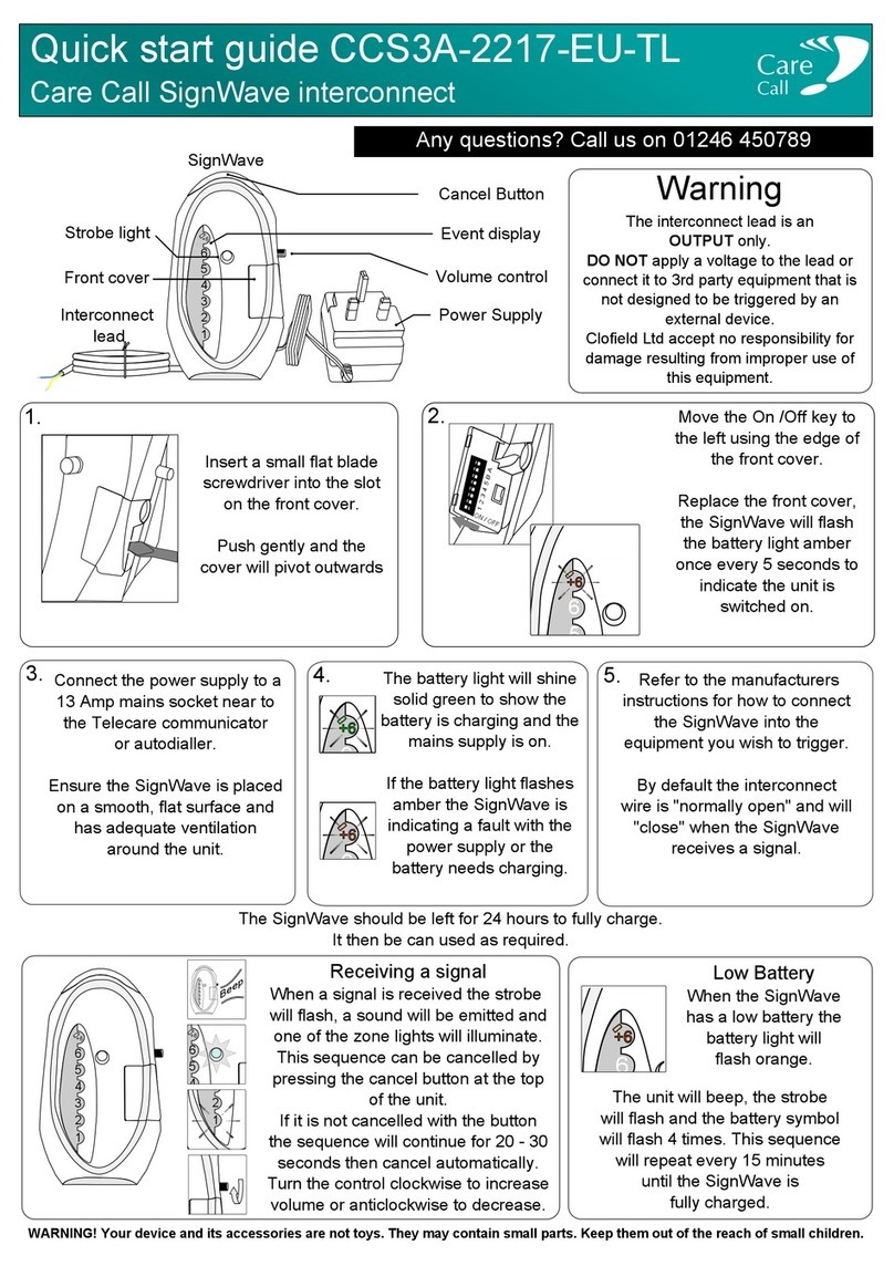
Care Call SignWave User manual

Care Call

Care Call SignWave User manual

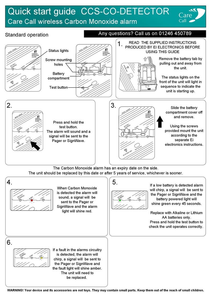
Care Call CCS-CO-DETECTOR User manual

Care Call

Care Call CCS-CO-DETECTOR User manual

Popular Security System manuals by other brands

Response SL3 Installation and operating manual

Response

Response SL3 Installation and operating manual

EVERSPRING SE203 quick start guide

EVERSPRING

EVERSPRING SE203 quick start guide

AV-GAD Bella I Series installation instructions

AV-GAD

AV-GAD Bella I Series installation instructions

Stanley Shelter FOB 9KX operating instructions

Stanley

Stanley Shelter FOB 9KX operating instructions

Aiphone 13710 Architectural & engineering specifications

Aiphone

Aiphone 13710 Architectural & engineering specifications

American Bus Video FHD4W quick start guide

American Bus Video

American Bus Video FHD4W quick start guide

Honeywell Ademco Vista-48LA Installation and setup guide

Honeywell

Honeywell Ademco Vista-48LA Installation and setup guide

Amperes EP1200 instruction manual

Amperes

Amperes EP1200 instruction manual

ESP HDview SHDV8KD4G manual

ESP

ESP HDview SHDV8KD4G manual

AJAX KeyPad Plus user manual

AJAX

AJAX KeyPad Plus user manual

AKO 52067 manual

AKO

AKO 52067 manual

SkyLink SA-001 Preliminary manual

SkyLink

SkyLink SA-001 Preliminary manual

minirookmelder MH3120 installation instructions

minirookmelder

minirookmelder MH3120 installation instructions

INIM Sol-S user manual

INIM

INIM Sol-S user manual

SECO-LARM ENFORCER SH-816S-SQ Series installation manual

SECO-LARM

SECO-LARM ENFORCER SH-816S-SQ Series installation manual

Velleman HOMEGUARD VCC2 manual

Velleman

Velleman HOMEGUARD VCC2 manual

DEXAPLAN BA 611 -  3 - REV 8-2007 manual

DEXAPLAN

DEXAPLAN BA 611 - 3 - REV 8-2007 manual

DSC PC1510 installation manual

DSC

DSC PC1510 installation manual

manuals.online logo
manuals.online logoBrands
  • About & Mission
  • Contact us
  • Privacy Policy
  • Terms and Conditions

Copyright 2025 Manuals.Online. All Rights Reserved.