manuals.online logo
Brands
  1. Home
  2. •
  3. Brands
  4. •
  5. Care Call
  6. •
  7. Security System
  8. •
  9. Care Call SignWave User manual

Care Call SignWave User manual

Quick start guide CCS3A-2217-EU-TL
Care Call SignWave interconnect
CCM3A-2216-EU-PIR-MKX
MOVEMENT MONITOR 11/12/13
USE MAINS POWER SUPPLY
PS3A-2207-UK ONLY
SILENT ALERT SA3000 SYSTEM
WWW.SILENT-ALERT.CO.UK CLOFIELD LTD. UK
TEL 01246 260045
Care
Call
MOVE KEY DOWN
TO SWITCH ON
Any questions? Call us on 01246 450789
12345
B
54
3
2
1
ON /OFF
ON
1
2
3
SignWave
Cancel Button
Event display
Volume control
Strobe light
Front cover
ON / OFF
1 2 3 4 5 B A
Insert a small flat blade
screwdriver into the slot
on the front cover.
Push gently and the
cover will pivot outwards
1. Move the On /Off key to
the left using the edge of
the front cover.
Replace the front cover,
the SignWave will flash
the battery light amber
once every 5 seconds to
indicate the unit is
switched on.
ON / OFF
1 2 3 4 5 B A
2.
A
4
+6
5
6
3. Connect the power supply to a
13 Amp mains socket near to
the Telecare communicator
or autodialler.
Ensure the SignWave is placed
on a smooth, flat surface and
has adequate ventilation
around the unit.
5. Refer to the manufacturers
instructions for how to connect
the SignWave into the
equipment you wish to trigger.
By default the interconnect
wire is "normally open" and will
"close" when the SignWave
receives a signal.
4.
A
4
+6
5
6
A
4
A
B
54
3
2
1
ON /OFF
ON
+6
1
2
3
4
5
6
Receiving a signal
When a signal is received the strobe
will flash, a sound will be emitted and
one of the zone lights will illuminate.
This sequence can be cancelled by
pressing the cancel button at the top
of the unit.
If it is not cancelled with the button
the sequence will continue for 20 - 30
seconds then cancel automatically.
Turn the control clockwise to increase
volume or anticlockwise to decrease.
1
2
3
+6
4
5
6
A
B
54
3
2
1
ON/OFF
ON
+6
1
2
3
4
5
6
Beep
4
5
+6
6
Low Battery
When the SignWave
has a low battery the
battery light will
flash orange.
The unit will beep, the strobe
will flash and the battery symbol
will flash 4 times. This sequence
will repeat every 15 minutes
until the SignWave is
fully charged.
The SignWave should be left for 24 hours to fully charge.
It then be can used as required.
A
A
B
54
3
2
1
ON /OFF
ON
+6
1
2
3
4
5
6
Interconnect
lead
Power Supply
The battery light will shine
solid green to show the
battery is charging and the
mains supply is on.
If the battery light flashes
amber the SignWave is
indicating a fault with the
power supply or the
battery needs charging.
A
4
+6
5
6
Warning
The interconnect lead is an
OUTPUT only.
DO NOT apply a voltage to the lead or
connect it to 3rd party equipment that is
not designed to be triggered by an
external device.
Clofield Ltd accept no responsibility for
damage resulting from improper use of
this equipment.
WARNING! Your device and its accessories are not toys. They may contain small parts. Keep them out of the reach of small children.
Advanced settings CCS3A-2217-EU-TL
Care Call SignWave interconnect
CCM3A-2216-EU-PIR-MKX
MOVEMENT MONITOR 11/12/13
USE MAINS POWER SUPPLY
PS3A-2207-UK ONLY
SILENT ALERT SA3000 SYSTEM
WWW.SILENT-ALERT.CO.UK CLOFIELD LTD. UK
TEL 01246 260045
Care
Call
MOVE KEY DOWN
TO SWITCH ON
Any questions? Call us on 01246 450789
12345
B
54
3
2
1
ON /OFF
ON
1
2
3
A
4
Strobe and sounder options.
It is possible to change the pitch of the sound produced and deactivate both the strobe and sounder.
4. The strobe and sounder configuration combinations are shown below.
Zone 1 + strobe + Normal Frequency beep = Normal frequency sound + strobe (default setting)
Zone 2 + strobe + High Frequency beep = Zone key + high frequency sound + strobe
Zone 3 + normal frequency beep = Zone key + normal frequency sound with no strobe
Zone 4 + high frequency beep = Zone key + high frequency sound with no strobe
Zone 5 + strobe + no beep = Zone key, no sound + strobe
1
ON /OFF
ON
1
2
After a few seconds the sounder
will beep once, the strobe will flash
and each zone key will light from
bottom to top in sequence.
Keep holding the button.
A sequence of strobe
flashes and sounds in
combination with a zone
key will occur.
Release the button when
the desired combination
has been displayed.
1. 2.
To alter the strobe and
sounder options press
and hold the cancel
button.
A
B
54
3
2
+6
3
4
5
6
3.
Changing the system channel code
NOTE. In most cases it is not necessary to change the system code. However, when one or more systems are in close
proximity, system codes can be used to avoid interference from other Care Call systems using up to a maximum of
16 channels.
The SignWave is supplied with no
system code switches set (system code 1).
For reference this is the factory setting
should you need to re-set the unit.
System codes can be set using
key switches 1 - 4.
The diagram to the right shows the 16
possible combinations.
Be sure that the same system code is set on
all monitors to be used in the system.
NOTE. Care Call receivers have an ON/OFF
switch, Care Call monitors do not.
Here we have a Care Call SignWave and Mini Monitor set to
system channel 2.
Ensure when setting system channel keys you remember to ignore the
SignWave ON/OFF switch or the equipment will be on different
system channels .
The diagram to the right shows an incorrect attempt to set the system
to channel code 2 (shown as an example to avoid possible confusion).
The correct settings are shown to the left.
1 2 3 4 5 6 7 8
INCORRECT
ON/OFF
A
B
5
4
3
2
1
1 2 3 4 5 6 7 8
ON/OFF
A
B
5
4
3
2
1
CORRECT
23456 7 8
1
ON/OFF
A
B
5
4
3
2
1
ON/OFF
A
B
5
4
3
2
1
ON/OFF
A
B
5
4
3
2
1
ON/OFF
A
B
5
4
3
2
1
ON/OFF
A
B
5
4
3
2
1
ON/OFF
A
B
5
4
3
2
1
ON/OFF
A
B
5
4
3
2
1
ON/OFF
A
B
5
4
3
2
1
9 10 1211 13 14 15 16
ON/OFF
A
B
5
4
3
2
1
ON/OFF
A
B
5
4
3
2
1
ON/OFF
A
B
5
4
3
2
1
ON/OFF
A
B
5
4
3
2
1
ON/OFF
A
B
5
4
3
2
1
ON/OFF
A
B
5
4
3
2
1
ON/OFF
A
B
5
4
3
2
1
ON/OFF
A
B
5
4
3
2
1
ON/OFF
A
B
5
4
3
2
1
1.
With the SignWave
switched on, move switch
5 to the left
2. This will increase the range
of the Pager from 100M
(in open air),
to approximately 1000M
(in open air).
Operating Range
500M
Increasing system range
It is possible to increase the range of the system.
Interconnect settings CCS3A-2217-EU-TL
Care Call SignWave interconnect
CCM3A-2216-EU-PIR-MKX
MOVEMENT MONITOR 11/12/13
USE MAINS POWER SUPPLY
PS3A-2207-UK ONLY
SILENT ALERT SA3000 SYSTEM
WWW.SILENT-ALERT.CO.UK CLOFIELD LTD. UK
TEL 01246 260045
Care
Call
MOVE KEY DOWN
TO SWITCH ON
Any questions? Call us on 01246 450789
12345
B
54
3
2
1
ON /OFF
ON
1
2
3
A
4
1
ON /OFF
ON
1
2
ON/OFF
A
B
5
4
3
2
1
1.
With the SignWave
switched on, move switch
A to the left
2. This will close the relay
contacts. The contacts will
"open" when a signal
is received.
Changing the interconnect output
It is possible to to change the default setting of normally open to normally closed.
NOTE: Only use this feature for equipment that require a "normally closed" input.
Transmitter Settings
The Interconnect SignWave will receive any Care Call signal sent from a transmitter on the same
system code.
HOWEVER: to trigger an interconnected device the transmitter must be configured to a special zone 13
1 2 3 4 5 6 7 8
13 Switch keys 7 & 8 on.
The transmitter will now
transmit zone 13.
CCF3A-2219-EU, CCF3A-2219-EU-GFOB, CCS-CO-DETECTOR, CCS-SMOKE-ION, CCS-SMOKE OPTO,
CCS-HEAT-DETECTOR
1.
To change the zone you need to
reset the monitor:
Remove the battery,
press the push button,
replace the battery.
PUSH
Press and release the
button whilst the light
is green. The light will
flash red once, twice
then three times and
so on up to twelve.
3.
PUSH
To set the zone
number, briefly press
the test button at the
desired number
of flashes
(13 in this instance).
The indicator light will
flash green to confirm
the selection.
4.
The monitor will then
perform the battery voltage
level display and start as
normal. Press the test button
to confirm the correct zone
has been selected.
PUSH
5.
PUSH
After the flashing red/
green startup
sequence the light will
shine constant green.
2.
CCM4A-2214-EU, CCC4A-2212-EU, CCD4A-2220-EU
9
10
11
12
13
14
15
16
13
CCM3A-2216-EU, CCM3A-2216-EU-PIR
Switch keys 15 & 16 on.
The transmitter will now
transmit zone 13.

Other Care Call Security System manuals

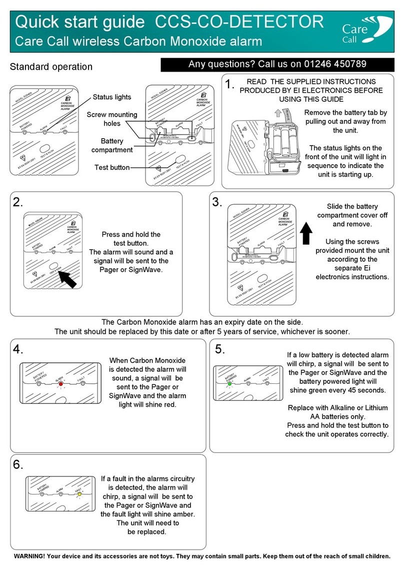
Care Call CCS-CO-DETECTOR User manual

Care Call

Care Call CCS-CO-DETECTOR User manual

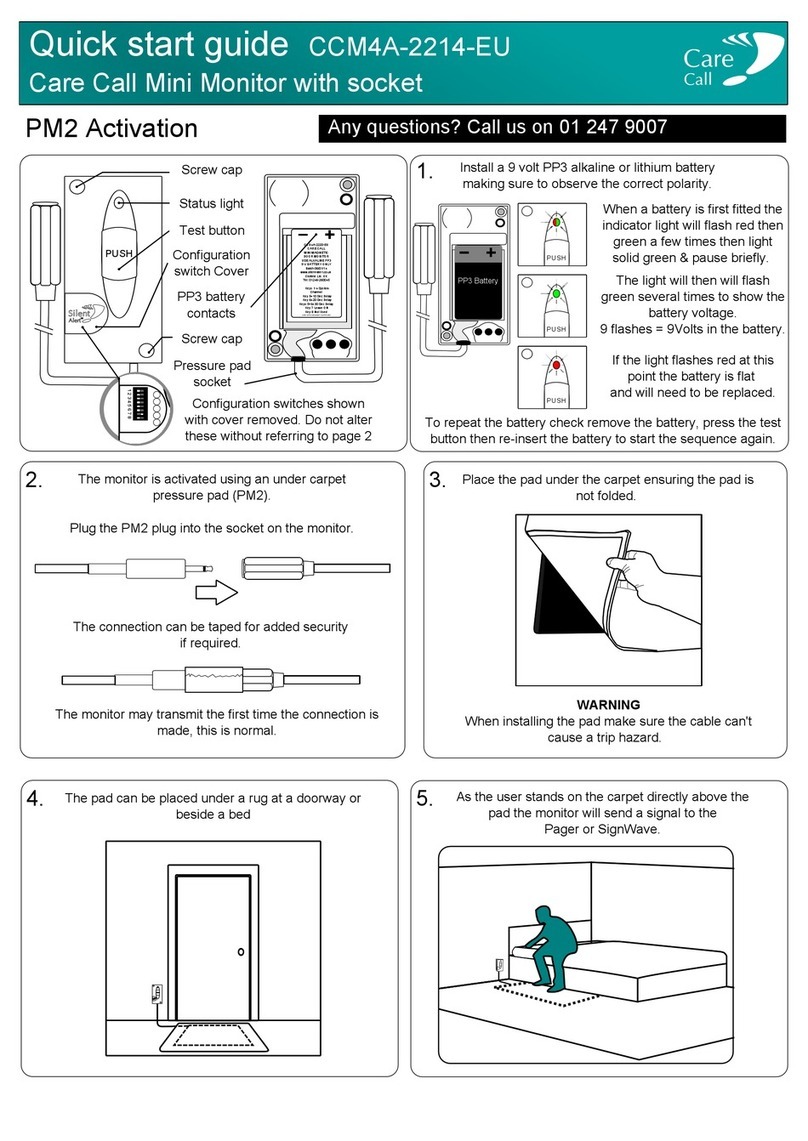
Care Call CCM4A-2214-EU User manual

Care Call

Care Call CCM4A-2214-EU User manual

Popular Security System manuals by other brands

Channel Plus 9510HHR user guide

Channel Plus

Channel Plus 9510HHR user guide

Abus PPDF18000 quick guide

Abus

Abus PPDF18000 quick guide

Abus SECVEST Installer manual

Abus

Abus SECVEST Installer manual

Qlight SEDLR operating manual

Qlight

Qlight SEDLR operating manual

Q-See DVR user manual

Q-See

Q-See DVR user manual

Q-See qr404-411 Quick installation guide

Q-See

Q-See qr404-411 Quick installation guide

HIK VISION AX PRO M2 quick start guide

HIK VISION

HIK VISION AX PRO M2 quick start guide

i3 International 2i0008 Series Quick connection guide

i3 International

i3 International 2i0008 Series Quick connection guide

Lloyd's LC-1303 Quick installation guide

Lloyd's

Lloyd's LC-1303 Quick installation guide

Abus FUSG50000 installation instructions

Abus

Abus FUSG50000 installation instructions

Sonic Alert USS 360 instruction manual

Sonic Alert

Sonic Alert USS 360 instruction manual

Sonic Alert HomeAware II user guide

Sonic Alert

Sonic Alert HomeAware II user guide

M-TI CX FLEX 4A product manual

M-TI

M-TI CX FLEX 4A product manual

Watchguard NVR4ENTPACK v1.2 Quick installation guide

Watchguard

Watchguard NVR4ENTPACK v1.2 Quick installation guide

Sonic Alert HA360DR-II user guide

Sonic Alert

Sonic Alert HA360DR-II user guide

Paradox Magellan MG-6060 Reference and installation manual

Paradox

Paradox Magellan MG-6060 Reference and installation manual

Qlight EMCL70 manual

Qlight

Qlight EMCL70 manual

Abus TVAC15300 user manual

Abus

Abus TVAC15300 user manual

manuals.online logo
manuals.online logoBrands
  • About & Mission
  • Contact us
  • Privacy Policy
  • Terms and Conditions

Copyright 2025 Manuals.Online. All Rights Reserved.