B
F
C
D
E
A
⬉ᴎᅮᄤ
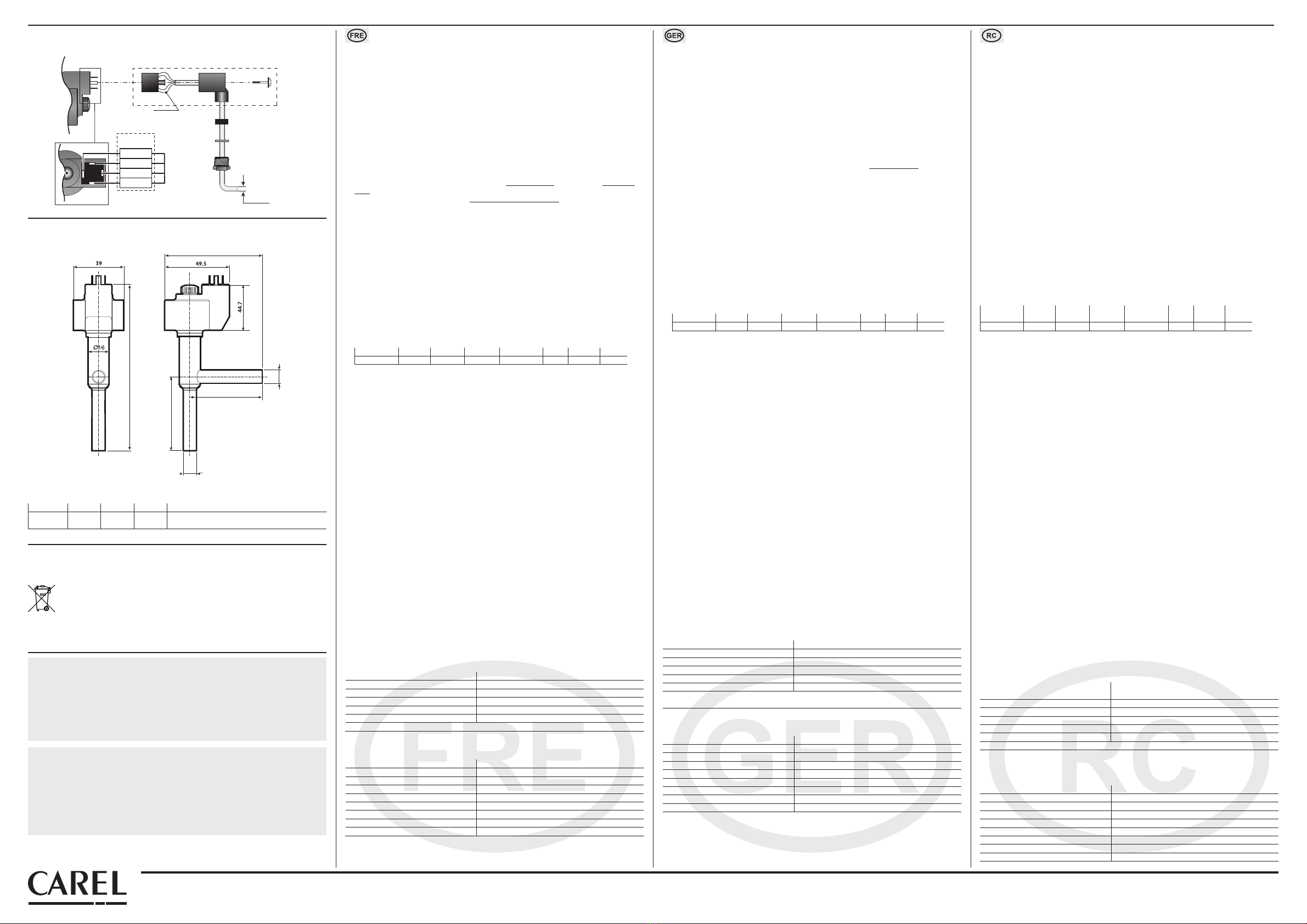
stator
ൿ
gasket
ൿ⠛
washer
ッᄤᥦ
terminal block
䖲༈
E2VCON0000
E2VCON0000
connector
AWG 18-22
Ø4-6 mm
䖲Ⲧ
connector case
㶎䩝
screw
㋻㶎ϱ
fastening screw
2
3
4
1
4
2
3
1
ⱑ㡆/White
咘㡆/Yellow
ẩ㡆/Brown
㓓㡆/Green
CAREL
E2VCAB****
尺寸:单位mm (inch)/ Dimensions in mm (inch)
电气连接/ Electrical connections
+05C000342 - rel. 2.0 - 27.09.2011
CAREL INDUSTRIES - HQs
Via dell’Industria, 11 - 35020 Brugine - Padova (Italy) - Tel. (+39) 049.9716611
友情提示
CAREL产品是最先进的产品,其操作方法在随附的技术文件中有所说明,您甚至可以在购买前从
www.carel.com网站上下载。
为了达到特定的最终装置和/或设备的预期效果,客户(最终设备的制造商、开发商或工程商)可以
对本产品进行配置,但与此相关的所有责任和风险由客户承担。如果未能完成用户手册中要求/指明
的操作,可能会导致最终产品出现故障;在这种情况下,CAREL不承担任何责任。客户必须仅以本
产品相关文件规定的方法使用本产品。 CAREL就其产品应承担的责任在CAREL一般合同条款中有所
说明,可以从www.carel.com网站上和/或与客户签订的特定协议中获得。
IMPORTANT WARNINGS
The CAREL product is a state-of-the-art product, whose operation is specied in the technical documentation
supplied with the product or can be downloaded, even prior to purchase, from the website www.carel.com.
The client (builder, developer or installer of the nal equipment) assumes every responsibility and risk relating
to the phase of conguration the product in order to reach the expected results in relation to the specic
nal installation and/or equipment. The lack of such phase of study, which is requested/indicated in the user
manual, can cause the nal product to malfunction of which CAREL can not be held responsible. The nal
client must use the product only in the manner described in the documentation related to the product itself.
The liability of CAREL in relation to its own product is regulated by CAREL’s general contract conditions edited
on the website www.carel.com and/or by specic agreements with clients.
Fig. 3
Fig. 4
废品处理
此装置(或产品)必须按照当地关于废弃物品处理的相关强制法规,单独进
行处理。
Disposal of the product
The appliance (or the product) must be disposed of separately in accordance
with the local waste disposal legislation in force.
Caractéristiques générales
Le détendeur électronique E2V-C est destiné a être installé dans les circuits frigori ques
comme dispositif à détente pour le liquide réfrigérant en utilisant comme signal de réglage
la surchaue calculée au moyen d’une sonde de pression et de température situées à la sortie
de l’évaporateur. L’utilisation des instruments CAREL ou bien l’utilisation des instruments approuvés par
CAREL même est recommandée pour le pilotage des E2V-C.
Ne pas utiliser les détendeurs E2V pour d’autres utilisations opérationnelles que celles reportées
ci-après.
Positionnement
Les détendeurs E2V-C, étant bidirectionnelles, peuvent être installés avec l’entrée du réfrigérant du côté
du raccord latéral (voir Fig. 1) ou par le bas. Installer toujours un ltre mécanique à l’entrée du uide
de refroidissement. L’orientation spatiale est possible pour chaque conguration exceptée celle avec le
stator dirigé vers le bas (détendeur renversé). La position conseillée pour le détendeur E2V-C est la même
que celle pour le détendeur thermostatique de type traditionnel c’est-à-dire placé avant l’évaporateur et
avant un éventuel distributeur.
Les capteurs de température et de pression (non fournis avec les E2V-C) doivent être positionnés
immédiatement après l’évaporateur et en faisant particulièrement attention à:
•ce que le capteur de température soit installé avec la pâte conductrice et qu’il soit isolé thermique-
ment de façon appropriée;
•ce que les deux capteurs soient installés AVANT des dispositifs éventuels pouvant altérer la mesure de
pression (ex. soupapes) et/ou température (ex. échangeurs).
Installation et manipulation
Les vannes E2V-C doivent être soudées.
Pour les vannes à souder respecter l’ordre indiqué sur la gure en procédant comme suit:
1. si le stator est déjà assemblé, le retirer en dévissant l’écrou de xation et en l’enlevant;
2. enrouler un chion mouillé et passer à la soudure sans la surchauer en orientant la amme vers l’ex-
trémité des raccords (pour eectuer un soudo-brasage sans altérer l’étanchéité de la zone de soudure,
utiliser un alliage avec une température de fusion inférieure à 650 °C ou une teneur en argent de plus
de 25%);
3. une fois que le détendeur est refroidi, réinsérer le stator sur la cartouche en le poussant jusqu'à la
butée, visser l’écrou noir jusqu'à la butée au point de déformer la couronne circulaire en caoutchouc
du stator (couple de serrage: 0,3 Nm);
4. Raccorder le connecteur déjà câblé au moteur pas à pas dans le logement correspondant et serrer la vis
avec un couple de 0,5 Nm en suivant les indications de la Fig. 3. Connecter ensuite l'extrémité quadripo-
laire du câble aux bornes correspondantes du Driver CAREL EVD*** ou du régulateur homologué CAREL
et con gurer les paramètres selon la valeur reprise au tableau ci-dessous.
Model Step min Step max step close Step/s speed mA pk mA hold % duty
CAREL 50 480 500 50 450 100 30
Les contrôleurs Carel pour détendeur électronique prévoient l’augmentation du cycle de fonctionne-
ment de 30% à 100% en phase de fermeture dans le but de diminuer les temps d’arrêt; pour accélérer
davantage cette phase, il est possible de piloter la vanne à une fréquence maximale de 150 pas/sec.
Pour plus d’informations sur les paramètres à con gurer dans le driver, consulter le manuel du contrôle.
ATTENTION: Les détendeurs CAREL sont fournis en position complètement ouverte. Si le détendeur est
activé avant d’être soudé sur le circuit frigori que, il doit impérativement être remis en position com-
plètement ouverte pour prévenir les hautes températures qui pourraient endommager les composants
internes lors de la soudure.
Ne pas exercer de torsions ou de déformations sur la soupape ou sur les tubes d’assemblage -
Ne pas taper sur la soupape avec un marteau ou des outils de ce genre - Ne pas utiliser de pinces
ou d’autres instruments qui pourraient déformer la structure externe ou endommager les organes
internes - Ne jamais orienter la emme en direction de la soupape.
Ne pas approcher des aimants ou des champs magnétiques de la soupape.
Ne pas installer ou utiliser en présence de:
• déformation ou endommagement de la structure externe;
• fort impact dû à une chute par exemple;
• endommagement de la partie électrique (stator, boîtier de contacts, connecteur,...).
CAREL ne garantit pas le fonctionnement de la soupape en cas de déformation de la structure exter-
ne ou en cas d’endommagements des parties électriques.
ATTENTION: La présence de particules dues à des saletés pourrait causer des dysfonctionnements
de la vanne.
Connexions Electriques
Connecter un câble quadripolaire au connecteur à câbler IP65 (E2VCON****) E2V-C suivant le schéma
reporté ci-dessous: le connecteur est du type standard DIN 43650.
Éventuellement connecter directement un connecteur co-moulé IP67 (E2VCAB***) dont le schéma corre-
spond à 1 Vert, 2 Jaune, 3 Marron, 4 Blanc. Pour les phases du moteur, les conducteurs AWG18-22 sont
conseillés alors qu’un câble quadripolaire doit avoir un diamètre externe de 4 à 6 mm pour permettre
une prise adaptée du joint externe. Puis, relier les quatre phases du moteur à votre dispositif pilote de
façon à ce que la phase n°1 de la E2V-C corresponde à la borne n°1 du pilote et ainsi de suite.
Attention: la phase n°4 est indiquée sur le stator de la soupape avec le symbole de la terre.
Un connecteur co-moulé blindé est disponible comme option (E2VCABS***) pour des applications
présentant des brouillages électromagnétiques particuliers. Norme référentielle en vigueur 89/336/CEE
et modi cations successives.
Spécications opérationnelles CAREL E2V
Compatibilité R22, R134a, R404A, R407C,R410A, R744, R507A, R417A
Pression d’exercice maximale (MOP) jusqu’à 140 bar (2030 psi)
Pression d’exercice maximale (MOPD) 120 bar (1740 psi)
P.E.D. Gr. 2, art. 3, par. 3
Température du réfrigérant -40T65 °C (-40T149 °F)
Température ambiante -30T50 °C (-22T122 °F)
Contacter CAREL pour des conditions opérationnelles diérentes ou Réfrigérants alternatifs.
Stator CAREL E2V
Stator bipolaire en basse tension (2 phases - 24 détentes polaires)
Courant de phase 450 mA
Fréquence de pilotage 50 Hz (jusqu’à 150 Hz dans le cas de fermeture d’urgence)
Résistance de phase (25 °C) 36 Ohm ± 10%
Index de protection IP65 avec E2VCON****, IP67 avec E2VCAB***
Angle de pas 15°
Avancement linéaire/pas 0,03 mm (0,0012 inch)
Connexions 4 ls (AWG 18/22)
Pas de fermeture complète 500
Pas de réglage 480
Allgemeine Merkmale
Das elektronische Expansionsventil E2V-C wird im Kältekreislauf als Entspannungsorgan des
Kältemittels installiert; dabei wird die anhand eines Druck- und Temperaturfühlers am
Verdampferausgang gemessene Überhitzung als Regelsignal verwendet. Für die Steuerung der
E2V-C werden CAREL-Geräte oder von CAREL o ziell anerkannte Instrumente empfohlen.
Bitte beachten Sie die nachstehend angeführten Betriebsbedingungen.
Positionierung
Die Positionierung des Kältemitteleingangs kann beim bidirektionalen E2V-C-Ventil von der Seite (siehe
Fig. 1) oder von unten erfolgen. Installieren Sie vor dem Kältemitteleingang immer einen mechani-
schen Filter sowohl.
Die räumliche Ausrichtung ist in jeder Kon guration, außer mit nach unten gerichtetem Stator, möglich
(auf den Kopf gestelltes Ventil). Die für das E2V-C-Ventil empfohlene Position ist dieselbe eines traditionel-
len Thermostatventils, d.h. vor dem Verdampfer und dem eventuellen Verteiler.
Die Temperatur- und Druckfühler (nicht im Lieferumfang enthalten) müssen unmittelbar hinter dem
Verdampfer angebracht werden. Achten Sie bitte darauf, dass:
•der Temperaturfühler mit Wärmeleitpaste installiert und angemessen thermisch isoliert ist;
•beide Fühler VOR eventuellen Druck-und/oder Temperaturverändernden Vorrichtungen installiert
sind (z. B. Ventile; Tauscher).
Installation und Handhabung
Die E2V-C-Ventile müssen gelötet. Befolgen Sie beim Verlöten die in der Abbildung dargestellten und
nachstehend angeführten Schritte:
1. Ist der Stator bereits montiert, lockern Sie die Sicherungsmutter und nehmen Sie ihn ab.
2. Wickeln Sie einen nassen Lappen um das Ventil und schweißen Sie, ohne das Ventil selbst zu
überhitzen; richten Sie die Flamme auf die Enden der Anschlussstücke (für eine bessere Verlötung
ohne Beeinträchtigung der Lötstellen sollte eine Legierung mit Schmelztemperatur unter 650 °C
oder mit Silbergehalt über 25% verwendet werden).
3. Den Stator erneut bis zum Endanschlag in den kalten Ventileinsatz einfügen und die schwarze Mutter
so fest verschrauben, bis der Gummiring des Stators leicht verbogen ist (Drehmoment 0,3 Nm);
4. Den vorverdrahteten Steckverbinder in den Schrittmotor einfügen und die Schraube nach den
Anleitungen der Fig. 3 mit rund 0,5 Nm Drehmoment festschrauben. Das Vierleiterkabelende an die
entsprechenden Klemmen des CAREL-Treibers EVD*** oder an eine andere zugelassene CAREL-
Steuerung anschließen und die Parameter gemäß Parameter-Set der nachstehenden Tabelle einstellen.
Modell Step min Step max step close Step/s speed mA pk mA hold % duty
CAREL 50 480 500 50 450 100 30
Die Carel-Steuerungen für das elektronische Ventil sehen die Erhöhung des Duty Cycle von 30% auf
100% in der Schließungsphase vor, um die Stoppzeiten zu vermindern; für eine zusätzliche Beschleu-
nigung dieser Phase kann das Ventil auf einer max. Frequenz von 150 Schritt/Sek. gesteuert werden.
Für weitere Informationen über die im Treiber einzustellenden Parameter siehe das technische
Handbuch der Steuerung.
ACHTUNG: Die Carel-Ventile werden in einer komplett oenen Position geliefert. Sollte das Ventil vor
dem Verlöten im Schaltkreis aktiviert werden, muss es zuerst vollständig geönet werden, damit die
hohen Temperaturen die internen Bauteile nicht beschädigen.
Achten Sie darauf, dass das Ventil oder die Anschlussleitungen nicht Drehungen oder Verformungen
ausgesetzt sind. Schlagen Sie auf das Ventil nicht mit Hammer oder anderen Gegenständen ein.
Benutzen Sie nicht Zangen oder andere Werkzeuge, welche die Außenstruktur verformen oder die
internen Organe beschädigen könnten. Richten Sie die Flamme nie auf das Ventil. Bringen Sie das
Ventil nie in die Nähe von Magneten oder Magnetfeldern. Installieren oder benutzen Sie das Ventil
nie bei:
• Verformung oder Beschädigung der Außenstruktur;
• starkem Aufprall, z. B. nach einem Fall;
• Beschädigung des elektrischen Teils (Stator, Kontakthalter, Steckverbinder,...).
CAREL haftet im Fall einer Verformung der Außenstruktur oder Beschädigung der elektrischen Teile
nicht für den korrekten Betrieb des Ventils.
ACHTUNG: Vorhandene Schmutzteilchen könnten Funktionsstörungen am Ventil hervorrufen.
Elektrische Anschlüsse
Schließen Sie ein vierpoliges Kabel an den Steckverbinder IP65 (E2VCON****) E2V-C nach dem unten
abgebildeten Schema an. Der Steckverbinder besitzt den Standard DIN 43650. Schließen Sie eventuell
einen Stecker für Extrembedingungen IP67 (E2VCAB***) direkt an (Farbübersicht: 1 Grün, 2 Gelb, 3 Braun,
4 Weiß). Als Kabelquerschnitt wird AWG18-22 empfohlen, während das vierpolige Kabel einen Außen-
durchmesser von 4 bis 6 mm haben muss, damit die externe Dichtung ihre Funktion erfüllen kann.
Schließen Sie anschließend die vier Phasen an Ihren Treiber an, damit die Phase 1 des E2V-C der Klemme
1 des Treibers entspricht etc.
Achtung: die Phase 4 ist auf dem Ventilstator mit dem Erdungssymbol angegeben.
Es ist ein optionaler Stecker für Extrembedingungen mit Schirm (E2VCABS***) für Anwendungen mit
besonderen elektromagnetischen Störungen verfügbar. Unter Bezugnahme auf die geltende Gesetzge-
bung 89/336/CEE und nachfolgende Änderungen.
Betriebsbedingungen CAREL E2V
Kompatibiltät R22, R134a, R404A, R407C,R410A, R744, R507A, R417A
Max. Betriebsdruck (MOP) jusqu’à 140 bar (2030 psi)
Max. Betriebs- ¢P (MOPD) 120 bar (1740 psi)
P.E.D. Gr. 2, art. 3, par. 3
Temperatur des Kältemittels -40T65 °C (-40T149 °F)
Umgebungstemperatur -30T50 °C (-22T122 °F)
Kontaktieren Sie CAREL bei hiervon abweichenden Betriebsbedingungen oder verschiedene kühefeüs-
sigkeit.
Stator CAREL E2V
Zweipoliger Niederspannungsstator (2 Phasen - 24 Polschuhe)
Phasenstrom 450 mA
Steuerfrequenz 50 Hz (bis zu 150 Hz im Fall der Notschließung)
Phasenwiderstand 25 °C 36 Ohm ± 10%
Schutzart IP65 mit E2VCON****, IP67 mit E2VCAB***
Schrittwinkel 15°
Linearer Vorschub/Schritt 0,03 mm (0,0012 inch)
Anschlüsse 4 Drähte (AWG 18/22)
Schritte für vollständige Schließung 500
Regelschritte 480
一般特性
E2V是一种用于制冷系统中的膨胀节流装置(电子膨胀阀),它通过测算过热度进行节
流控制的。通过安装在蒸发器出口的压力和温度传感器,电子膨胀阀可以读取温度、
压力信号,进而计算出过热度。E2V只能和CAREL的相关设备配套使用。
请不要在正常运行条件之外使用E2V阀,如下所述。
安装位置
E2V阀是双向运行的。 安装时可与制冷剂入口从侧面或底部连接起来(参考图1)。
通常要在制冷剂入口前安装一个机械式过滤器,同焊接的阀(E2V***S***)和阀接头在一起
(E2V***R***),在这种情况下,过滤器是包含在产品包装内的。
除了不能上下颠倒 (即电机定子朝下安装)以外, E2V阀可以朝任何方向。
建议E2V阀的位置同传统的机械式阀一样,即在蒸发器和任何分配器之前。
温度和压力传感器(不是同E2V阀一起提供的)必须安装在紧邻蒸发器出口的位,确保:
•温度传感器安装时使用了导热胶,并且能充分地与外部热绝热;
• 两个传感器都要安装在任何会改变压力(如阀)和/或温度(如热交换器)装置之前。
焊接和操作
E2V阀有焊接连接型(E2V***S***)或管路连接型(E2V***R***)。
对于焊接连接型,请按照下图所说明的步骤操作:
1. 如果已经安装了定子,将紧固定子的螺帽旋开,拆下定子;
2. 在阀体上包一块湿布,在进行焊接时,不要使阀过热,瞄准火焰到接头末端,(为了使钎焊
更好,而不影响阀体与接头之间的焊接密封性,使用熔化温度低于650 °C的合金或使用银含
量超过25%的合金)。
3. 当阀被冷却后,插入定子,将其完全推进,然后拧紧黑色螺帽直到在钉子上的橡胶垫圈稍稍
变形(紧固时扭矩为0.3 Nm)。
4. 如Fig. 3所示,将预接线的接头连接到步进电机的槽上,紧固螺丝,扭矩为0.5 Nm。然后将
4-pin的线连接到CAREL EVD***驱动器相对应的端口上,或其它已经被认可的CAREL控制器上,
根据下表所列出的值设定参数。
类型 最少步数 最多步数 关闭步数 步/秒
速度
相电流
mA
静态相
电流
占空
比%
CAREL 50 480 500 50 450 100 30
当关阀时,为了加快关闭速度,电子膨胀阀占空比可从30%提高到100%;要取得更快速
度,可使阀的最大励磁速度为150步/秒。
关于被设定在驱动器上的参数的其它信息,请参考控制器用户手册。
对于带压缩接头的阀,用恰当规格的轴接将接头紧固到回路上,再从第4点开始进行。
不要对阀或连接管线施加扭力或变形压力。
不要用锤子或其它物品敲击阀。
不要使用可能使外部结构变形或损坏内部零件的钳子或其它工具。
不要将火焰对准阀。
不要将阀放在靠近磁场的地方。
在下列状况下,不要安装或使用阀:
• 外部结构变形或损坏;
• 发生很严重的意外事件,例如产品摔落;
• 电子部件被损坏(定子,接触运载装置,连接头等等)。
在外部结构变形或电子部件被损坏的情况下,CAREL不能保证阀的运行。
如果有灰尘,可能会使阀出现故障。
• 安装以后, 检查密封性。
• 在安装管头进入阀体之前,不要移动阀头,以避免装配不当。
• 这个阀是个承压设备,必须安装一个独立的安全压力保护系统。
• 如果超出规定的范围使用该阀,部分性能规格可能无效
• 在运行压力下,避免变形,撞击,火苗及液体腐浊。
• 当阀运行中,不要拆开阀。
在进行维修和拆开之前,检查没有受压液体。
电气连接
连接一根四芯线到一个防护等级为IP65的连接头(E2VCON***),根据下图说明:这是一个标准的
DIN 43650连接头。
或者连接一个防护等级为IP67的模压好的连接头(E2VCAB****),1绿色,2黄色,3棕色,4白色。
使用的四芯连接线外径必须在4~6mm之间,确保与线缆套管之间合适的紧密性。
然后连接四个电机相到驱动器,E2V上的相1对应驱动器上的端口1,依次类推。
重要:相4在阀定子上标示了接地标志。
根据EEC规范89/336要求和之后的修正说明,对于有电磁干扰问题的应用,可提供一个选配的屏
蔽式模压连接头(E2VCAB****)。
CAREL E2V运行规格
兼容制冷剂 R22, R134a, R404A, R407C,R410A, R744, R507A, R417A
R717 (氨水,仅用于E2V**BS00*)
最高运行压力 (MOP) 高达45 bar (653 psi)
最大运行压差DP(MOPD) 35 bar (508 psi)
P.E.D. Gr. 2, art. 3, par. 3
制冷剂温度 -40~65 °C (-40~149 °F)
环境温度 -30~50 °C (-22~122 °F)
关于其它运行条件或可选择的制冷剂,请联系CAREL
CAREL E2V定子
两极定子,低电压(2对极 – 24扩展磁极)
相电流 450 mA
控制频率 50 Hz (紧急关闭情况下,最大到)
相电阻(25°C) 36 Ohm ± 10%
防护等级 带E2VCON***为IP65,带E2VCAB***为IP67
步距角 15°
线性前进/线性步进式 0,03 mm (0,0012 inch)
连接线 4芯(AWG 18/22)
完全关闭步数 500
控制步数 480
CAREL保留不预先告知即修改产品的权利。/ CAREL reserves the right to modify the features of its products without prior notice
型号/model A B C D
E2V**CS00* 126.8 mm
(4.99 inch)
74.3 mm
(2.92 inch)
54.8 mm
(2.16 inch)
56 mm
(2.20 inch)
Int.9/Est.10 mm
(in 0.35 out 0.39 inch)
Int.9/Est.10 mm
(in 0.35 out 0.39 inch)


