+050001441 - rel. 5.0 - 07.02.2022
CAREL INDUSTRIES - siedziba główna
Via dell’Industria, 11 - 35020 Brugine - Padova (Włochy)
T
el.
(+39)
0499716611
–
F
ax
(+39)
0499716600
–
www.carel
.com
–
e-mail:
[email protected]M
giallo / żółty
bianco / biały
rosso / czerwony
verde / zielony
viola / oletowy
blu / niebieski
A
C
B
D
123
rosso / czerwony
viola / oletowy
4
Wymiary w mm (calach) / Dimensions in mm (inch)
Typ zaworu
A B C D E F
E2V**USF0* korpus/ miedź
12-12mm ODF
130 mm
(5,12 cala).
73,1 mm
(2,88 cala)
52,3mm
(2,06 cala)
53,3mm
(2,10 cala)
Wewn.12/ Zewn.14mm
(Wewn. 0,47/Zewn. 0,55 cala)
Wewn.12/Zewn.14mm
(Wewn. 0,47/Zewn. 0,55 cala)
E2V**USM0* korpus/
miedź 16-16mm ODF
132mm
(5,20 cala)
75,1 mm
(2,96 cala)
54,3mm
(2,14 cala)
55,3mm
(2,18 cala)
(Wewn.16/ Zewn.18mm)
(Wewn. 5/8 / Zewn. 0,71 cala)
Wewn.16 / Zewn.18mm
(Wewn. 5/8 /Zewn. 0,71 cala)
E2V**UWA0* miedź
3/8”-3/8”ODF
130 mm
(5,12 cala).
73,1 mm
(2,88 cala)
52,3mm
(2,06 cala)
53,3mm
(2,10 cala)
Wewn.9,5 Zewn. 13 mm
(Wewn.3/8 / Zewn. 0,51 cala)
Wewn.9,5 Zewn. 13 mm
(Wewn.3/8 / Zewn. 0,51 cala)
E2V**UWB0* miedź
3/8"-1/2" ODF
130 mm
(5,12 cala).
73,1 mm
(2,88 cala)
52,3mm
(2,06 cala)
53,3mm
(2,10 cala)
Wewn.12.8 Zewn. 15mm
(Wewn.1/2 /Zewn. 0,59 cala)
Wewn.9,5 Zewn. 13 mm
(Wewn.3/8 / Zewn. 0,51 cala)
Uwaga:
kody E2V**U**0* mają kabel o długości
1 m i złącze XHP-6;
kody E2V**U**1* mają kabel o długości 2 m i
złącze XHP-6;
kody E2V**U**2* mają kabel o długości 0,3 m
oraz złącze serii Superseal 1,5.
Note: codes E2V**U**0* have a 1 m
long cable and XHP-6 connector;
codes E2V**U**1* have a 2 m long cable
and XHP-6 connector;
codes E2V**U**2* have a 0.3 m long cable
and Superseal series 1.5 connector.
Cewka Przewód Stan wzbudzenia
1 2 3 4 5 6 7 8
A/Biały 12V 12 V WYŁ. WYŁ. WYŁ. WYŁ. WYŁ. 12 V
B/Żółty WYŁ. 12V 12V 12 V WYŁ. WYŁ. WYŁ. WYŁ.
C/Zielony WYŁ. WYŁ. WYŁ. 12 V 12V 12 V WYŁ. WYŁ.
D/Niebieski WYŁ. WYŁ. WYŁ. WYŁ. WYŁ. 12V 12 V 12V
Połączenia elektryczne / Electrical connections
Rys. 3
Rys. 4
otwórz zawór /
open valve
zamknij zawór /
close valve
bianco / biały
giallo / żółty
giallo / żółty
verde / zielony
verde / zielony
blu / niebieski
blu / niebieski
rosso / czerwony
rosso / czerwony
viola / oletowy
A
Ø 35
Ø 16
45.9
23
C
D
B
Ø E
Ø F
M
giallo / yellow
bianco / white
rosso / red
verde / green
viola / violet
blu / blue
A
C
B
D
123
rosso / red
viola / violet
4
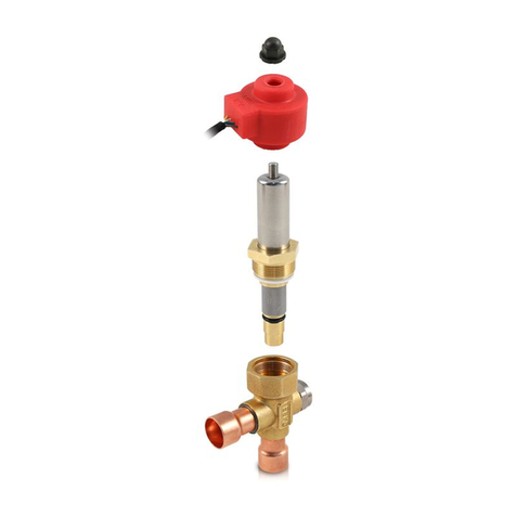
Características generales: La válvula electrónica E2V está diseñada para su instalación en circuitos frigoríficos
como dispositivo de expansión para el fluido refrigerante, utilizando como señal de regulación el recalentamiento
calculado mediante una sonda de Presión y una de Temperatura, situadas ambas a la salida del evaporador. Es
necesario un subenfriamiento del fluido adecuado en la entrada para evitar que la válvula trabaje en presencia de
burbujas de gas. Es posible que la válvula aumente su nivel de ruidosi la carga de refrigerante resultase insuficien-
te o se produjeran pérdidas de carga relevantes aguas arriba de la misma. Para el control de las E2V se recomienda
utilizar instrumentos CAREL u otros acreditados oficialmente por CAREL. No utilizar las válvulas E2V fuera de las
condiciones operativas que se indican a continuación.
Posicionamiento: La válvula E2V es bidireccional, con entrada preferente del líquido por la toma lateral (Fig. 1),
ya que favorece que la válvula permanezca cerrada en caso de interrupción de la alimentación eléctrica gracias
al efecto de la presión que empuja al obturador contra el orificio. En caso de utilizar válvulas de corte antes de
la válvula de expansión, es necesario configurar el circuito para que no se produzcan golpes de ariete en las
proximidades de la válvula. Es fundamental que la válvula de corte y la válvula de expansión no estén nunca
cerradas simultáneamente, para evitar sobrepresiones peligrosas en el circuito. Instalar siempre un filtro mecánico
antes de la entrada del refrigerante. Hay disponibles una serie de filtros opcionales: E2VFIL0100 para las válvulas
E2V**BSF** y E2V**BS1**; E2VFIL0200 para las válvulas E2V**BSM**; E2VFIL0300 para las válvulas E2V**BWA** o
E2V**BWB**. La orientación espacial resulta posible en cualquier configuración excepto con el estátor dirigido
hacia abajo (válvula invertida). La posición aconsejada de la válvula E2V es la misma que para una válvula termo-
stática de tipo tradicional; es decir, antes del evaporador y del eventual distribuidor. Los sensores de temperatura
y presión (que no se entregan con las E2V) se deben posicionar inmediatamente antes del evaporador y cuidando
de forma especial que:
•el sensor de temperatura se instale con pasta conductora y se haya aislado térmicamente de forma adecuada;
•ambos sensores se hayan instalado ANTES de cualquier dispositivo que altere la presión (por ejemplo, válvulas)
y/o la temperatura (por ejemplo intercambiadores).
Soldadura y manipulacion: Las válvulas E2V son para soldar (E2V***S***) o roscar (E2V***R*** y E2V***W***).
Para las válvulas a soldar, seguir las instrucciones indicadas en la figura, procediendo de la siguiente forma:
1. Si el Actuador está ya montado, quitarlo desenroscando el dado de fijación y soltándolo;
2. Insertar el filtro de red metálica (opcional) exclusivamente en el racor lateral de entrada (Fig.2-B) posicionándo-
lo en su lugar y bloqueándolo con el tubo del circuito, antes de soldar la válvula. ¡Atención! Utilizar este filtro
solo de forma monodireccional. En caso de utilizar la válvula de forma bidireccional, prever el filtro adecuado
en el circuito, sin utilizar el suministrado;
3. Enrollar un trapo mojado y proceder a realizar la soldadura, sin recalentarla, orientando la llama hacia el ex-
tremo de las piezas de unión (para una soldadura mejor sin alterar la estanqueidad de la zona de soldadura
utilizar aleación con temperatura de fusión inferior a 650 °C ó con contenido de plata superior al 25%);
4. Con la válvula fría, reinsertar el estator en el cartucho empujándolo hasta el tope, enroscando el dado negro
hasta su apriete completo, hasta deformar la corona circular de goma del estator (par de apriete 0,3 Nm);
5. Conectar el conector
ATENCIÓN: Las válvulas CAREL se suministran en posición de apertura completa. En el caso en que la válvula
sea accionada antes de su soldadura en el circuito, es necesario posicionarla completamente abierta para
evitar que la alta temperatura dañe los componentes internos.
No aplicar torsiones o deformaciones en la válvula o en los tubos de conexión - No golpear la válvula con
martillos u otros objetos - No utilizar pinzas u otras herramientas que podrían deformar la estructura externa
o estropear los componentes internos - Nunca dirigir la llama hacia la válvula.
No acercar la válvula a magnetos, imanes o campos magnéticos.
No proceder a la instalación o a la utilización en caso de:
•deformación o daños de la estructura interna;
•fuerte impacto debido, por ejemplo, a una caída;
•daños de la parte eléctrica (estátor, cable, conector,...).
CAREL no garantiza el funcionamento de la válvula en caso de deformación de la estructura externa o de
daños en las partes eléctricas.
ATENC.: la presencia de partículas debidas a suciedad podrían causar malos funcionamientos de la válvula.
Conexiones eléctricas: El estado de la E2V unipolar está dotado de un cable de 6 polos integrado de 1m ó 2m
de largo con conector XHP-6. Como alternativa, utilizar los códigos E2V**U**2* dotados de cable integrado de
0,3m de largo con conector tipo Superseal serie 1.5 (IP67) al que se conecta un cable de prolongación adecuado
(E2VCABS*U*) para aplicaciones de acuerdo con la directiva 2004/108/EC y sucesivas modificaciones. Conectar
el conector de alimentación (tipo XHP-6) al contraconector correspondiente de un driver unipolar compatible
teniendo cuidado de no invertir las fases de alimentación. Ver el esquema de conexiones en la Fig. 3.
Especicaciones operativas CAREL E2V-U
Compatibilidad:
Grupo 1: R1234yf; Hidrocarburos R290, R600, R600a, R32, R452B, R454A, R454B, R454C, R455A, R1270
Grupo 2: R22, R134a, R404A, R407C, R410A, R417A, R507A, R744, R1234ze, R448A, R449A, R450A, R513A, R32,
R452B, R454A, R454B, R454C, R455A, R407A, R407E, R407F, R1233zd
Máxima Presión de trabajo (MOP): CE certificación: 60 bar (870psi). UL certificación: 45bar (652 psi)
Máximo DP de trabajo (MOPD): 35 bar (508 psi) - 26 bar (377 psi) por E2V35*****
P.E.D.: Gr. 1 y 2, art. 4, pár. 3.
UL/CSA certication (UL 429 y CSA C22.2 no.139-2010): UL file n° E3045579, cURus (A1) - UR (A3-B2)
ATEX 2014/34/UE: las válvulas E2V**U**C* (válvulas sin estátor) se han sometido a evaluación según la norma-
tiva IEC 80079-36:2016, quedando demostrado que no constituyen una fuente potencial de ignición ni pueden
convertirse en una de ellas cuando funcionan con normalidad. Por tanto, la válvula (estátor excluido) no debe
clasificarse ni identificarse como Ex h. Si se utiliza en una zona ATEX, la válvula solo debe conectarse a un estátor
ATEX E2VSTAX*** especial.
Temperatura refrigerante: -40T70 °C (-40T158 °F) - Temperatura ambiente: -30T70 °C (-22T158 °F)
Ponerse en contacto con CAREL para condiciones operativas diferentes o refrigerantes altenativos.
Estátor CAREL E2V-U: Estátor unipolar de baja tensión
Tensión de alimentación 12 V
Frecuencia de control 50 Hz
Resistencia de fase (25°C) 40 Ohm ± 10%
Índice de protección IP67
Ángulo de paso 15°
Avance lineal/paso 0,03 mm (0,0012 inch)
Conexiones 6 polos (AWG 18-22) con cable integrado longitud:
-1 m con conector XHP-6 (códigos E2V**U**0*)
-2 m con conector XHP-6 (códigos E2V**U**1*)
-0,3 m con conector Superseal serie 1.5 (IP67, códigos E2V**U**2*).
Pasos de cierre completo 500
Pasos de regulación 480
Por al uso de estatores electromagnéticos E2VSTA **** con refrigerantes inflamables, se han evaluado y se ha
comprobado que cumplen con los siguientes requisitos:
•Anexo CC de IEC 60335-2-24: 2010 referido en la cláusula 22.109 y Anexo BB de IEC 60335-2-89: 2019 referido
en la cláusula 22.113; no se encontraron componentes de arco o chispas durante el funcionamiento normal
o en caso de falla;
•IEC 60335-2-24: 2010 (cláusulas 22.110)
•IEC 60335-2-40: 2018 (cláusulas 22.116, 22.117)
•IEC 60335-2-89: 2019 (cláusulas 22.114)
Las temperaturas superficiales del producto han sido medidas y verificadas durante las pruebas requeridas por IEC
60335 cl. 11 y 19 y se encuentra a no más de 272°C (522°F). La aceptabilidad de estos productos en la aplicación
del uso final en el que se utiliza refrigerante inflamable debe revisarse y juzgarse en la aplicación del uso final.
Caractéristiques générales: Le détendeur électronique E2V est destiné a être installé dans les circuits frigorifiques
comme dispositif à détente pour le liquide réfrigérant en utilisant comme signal de réglage la surchauffe calculée
au moyen d’une sonde de pression et de température situées à la sortie de l’évaporateur. Un sous-refroidissement
adapté du fluide en entrée est nécessaire pour éviter que la vanne ne fonctionne en présence de gaz flash. Il est
possible que le niveau de bruit produit par la vanne augmente lorsque la charge de fluide frigorigène s’avère
insuffisante ou en cas de fuites importantes de charge en amont de cette dernière. L’utilisation des instruments
CAREL ou bien l’utilisation des instruments approuvés par CAREL même est recommandée pour le pilotage des
E2V. Ne pas utiliser les détendeurs E2V pour d’autres utilisations opérationnelles que celles reportées ci-après.
Positionnement: La vanne E2V est bidirectionnelle, avec entrée du liquide de préférence par le raccord latéral
(Fig. 1), car cela permet à la vanne de rester fermée en cas d’interruption de l’alimentation électrique grâce à
l’effet de la pression qui pousse l’obturateur contre l’orifice. En cas d’utilisation de vannes d’arrêt avant la vanne
d’expansion, il faut configurer le circuit afin qu’il ne se produise pas de coup de bélier à proximité de la vanne. Il
est essentiel que la vanne d’arrêt et la vanne d’expansion ne soient jamais fermées en même temps, afin d’éviter
toute surpression dangereuse dans le circuit. Installer toujours un filtre mécanique avant l’entrée du réfrigérant.
Plusieurs types de filtres sont disponibles en option : E2VFIL0100 pour les vannes E2V**BSF** et E2V**BS1** ;
E2VFIL0200 pour les vannes E2V**BSM** ; E2VFIL0300 pour les vannes E2V**BWA** ou E2V**BWB**. L’orientation
spatiale est possible pour chaque configuration exceptée celle avec le stator dirigé vers le bas (détendeur renver-
sé). La position conseillée pour le détendeur E2V est la même que celle pour le détendeur thermostatique de type
traditionnel c’est-à-dire placé avant l’évaporateur et avant un éventuel distributeur. Les capteurs de température
et de pression (non fournis avec les E2V) doivent être positionnés immédiatement après l’évaporateur et en faisant
particulièrement attention à:
•ce que le capteur de température soit installé avec la pâte conductrice et qu’il soit isolé thermiquement de
façon appropriée;
•ce que les deux capteurs soient installés AVANT des dispositifs éventuels pouvant altérer la mesure de pression
(ex. soupapes) et/ou température (ex. échangeurs).
Soundage et manipulation: Le vannes E2V unipolaires sont disponibles avec raccords en cuivre à souder
(E2V**US*** et E2V***W***). Pour les vannes à souder respecter l’ordre indiqué sur la figure en procédant comme suit:
1. si le stator est déjà assemblé, le retirer en dévissant l’écrou de fixation et en l’enlevant;
2. Insérer le filtre dans le treillis métallique (en option), uniquement sur le raccord latéral d’entrée (Fig. 2-B) en le
positionnant en butée et en le bloquant avec le tuyau du circuit, avant de souder la vanne. Attention! Utiliser
ce filtre uniquement en mode monodirectionnel. En cas d’utilisation de la vanne en mode bidirectionnel,
prévoir un filtre adapté dans le circuit;
3. enrouler un chiffon mouillé et passer à la soudure sans la surchauffer en orientant la flamme vers l’extrémité
des raccords (pour effectuer un soudo-brasage sans altérer l’étanchéité de la zone de soudure, utiliser un
alliage avec une température de fusion inférieure à 650 °C ou une teneur en argent de plus de 25%);
4. une fois que le détendeur est refroidi, réinsérer le stator sur la cartouche en le poussant jusqu’à la butée, visser
l’écrou noir jusqu’à la butée au point de déformer la couronne circulaire en caoutchouc du stator (couple de
serrage: 0,3 Nm);
5. Raccorder le connecteur
ATTENTION: Les détendeurs CAREL sont fournis en position complètement ouverte. Si le détendeur est activé
avant d’être soudé sur le circuit frigorifique, il doit impérativement être remis en position complètement ouverte
pour prévenir les hautes températures qui pourraient endommager les composants internes lors de la soudure.
Ne pas exercer de torsions ou de déformations sur la soupape ou sur les tubes d’assemblage.
Ne pas taper sur la soupape avec un marteau ou des outils de ce genre.
Ne pas utiliser de pinces ou d’autres instruments qui pourraient déformer la structure externe ou endomma-
ger les organes internes.
Ne jamais orienter la emme en direction de la soupape.
Ne pas approcher des aimants ou des champs magnétiques de la soupape.
Ne pas installer ou utiliser en présence de:
•déformation ou endommagement de la structure externe;
•fort impact dû à une chute par exemple;
•endommagement de la partie électrique (stator, câble, connecteur,...).
CAREL ne garantit pas le fonctionnement de la soupape en cas de déformation de la structure externe ou en
cas d’endommagements des parties électriques. ATTENTION: La présence de particules dues à des saletés
pourrait causer des dysfonctionnements de la vanne.
Connexions Electriques: Le stator E2V unipolaire est doté d’un câble à 6 pôles intégré d’une longueur d’1m ou
2m avec un connecteur XHP-6. Le cas échéant, utiliser les codes E2V**U**2* équipés d’un câble intégré d’une
longueur de 0,3m avec un connecteur de type Superseal série 1.5 (IP67) auquel doit être connecté un câble de
rallonge (E2VCABS*U*) pour des applications conformément à la directive 2004/108/EC et modifications suc-
cessives. Brancher le connecteur d’alimentation (type XHP-6) au relatif contre-connecteur d’un pilote unipolaire
compatible en prenant soin de ne pas inverser les phases d’alimentation. Voir schéma de connexion à la Fig. 3.
Spécications opérationnelles CAREL E2V-U
Compatibilité
Groupe 1: R1234yf; hydrocarbures R290, R600, R600a, R32, R452B, R454A, R454B, R454C, R455A, R1270
Groupe 2: R22, R134a, R404A, R407C, R410A, R417A, R507A, R744, R1234ze, R448A, R449A, R450A, R513A, R32,
R452B, R454A, R454B, R454C, R455A, R407A, R407E, R407F, R1233zd
Pression d’exercice maximale (MOP): Certification CE: 60 bar (870 psi). Certification UL: 45 bar (652 psi)
Pression d’exercice maximale (MOPD): 35 bars (508 psi) - 26 bar (377 psi) pour E2V35*****
P.E.D.: Gr. 1 et 2, art. 4, par. 3.
UL/CSA certication (UL 429 et CSA C22.2 no.139-2010): UL file n° E3045579, cURus (A1) - UR (A3-B2)
ATEX 2014/34/EU: les vannes E2V**U**C* (vannes sans stator), ont été évaluées selon la norme CEI 80079-36:2016
démontrant qu’elles ne présentent aucune source d’inflammation réelle ou potentielle pendant leur fonctionne-
ment normal. La vanne, à l’exclusion du stator, ne doit donc pas être classée ni marquée comme équipement Ex h.
En cas d’utilisation dans une zone classée ATEX, coupler la vanne uniquement avec un stator dédié ATEX E2VSTAX***.
Température du réfrigérant: -40T70 °C (-40T158 °F) - Température ambiante: -30T70 °C (-22T158 °F)
Contacter CAREL pour des conditions opérationnelles différentes ou Réfrigérants alternatifs.
Stator CAREL E2V-U
Stator unipolaire en basse tension
Voltage d’alimentation 12 V
Fréquence de pilotage 50 Hz
Résistance de phase (25 °C) 40 Ohm ± 10%
Index de protection IP67
Angle de pas 15°
Avancement linéaire/pas 0,03 mm (0,0012 inch)
Connexions 6 pôles (AWG 18-22) avec un câble intégré d'une longueur de:
-1 m avec un connecteur XHP-6 (codes E2V**U**0*)
-2 m avec un connecteur XHP-6 (codes E2V**U**1*)
-0,3 m avec un connecteur Superseal série 1.5 (IP67, codes E2V**U**2*).
Pas de fermeture complète 500
Pas de réglage 480
En concerne l’utilisation des stators électromagnétiques E2VSTA **** avec des fluides frigorigènes inflammables,
il sont été évalués et conforme aux exigences suivantes:
•Annexe CC de la CEI 60335-2-24 : 2010 mentionnée dans la clause 22.109 et Annexe BB de la CEI 60335-2-89:
2019 mentionnée dans la clause 22.113; aucun composant d’arc ou d’étincelle n’a été trouvé pendant le fon-
ctionnement normal ou en cas de panne;
•CEI 60335-2-24: 2010 (clauses 22.110)
•CEI 60335-2-40: 2018 (clauses 22.116, 22.117)
•CEI 60335-2-89: 2019 (clauses 22.114)
Les températures de surface du produit ont été mesurées et vérifiées lors des tests requis par la norme IEC 60335
cl. 11 et 19 et trouvé ne dépassant pas 272°C (522°F). L’acceptabilité de ces produits dans l’application d’utilisation
finale où un réfrigérant inflammable est utilisé doit être examinée et jugée dans l’application d’utilisation finale.
Allgemeine Beschreibung: Das elektronische E2V-Ventil wird im Kältekreislauf als Entspannungsorgan des Käl-
temittels installiert; dabei wird die anhand eines Druck- und Temperaturfühlers am Verdampferausgang gemes-
sene Überhitzung als Regelsignal verwendet. Das Kältemittel im Einlass muss entsprechend unterkühlt werden,
damit das Ventil bei Vorhandensein von Flash-Gas nicht arbeitet. Bei unzureichender Kältemittelladung oder bei
erheblichen Druckverlusten vor dem Ventil könnte sich die Geräuschentwicklung des Ventils erhöhen. Für die
Steuerung von E2V-Ventilen werden CAREL-Geräte empfohlen. Beachten Sie die nachstehend angeführten Be-
triebsbedingungen.
Positionierung: Das E2V-Ventil arbeitet bidirektional; als Einlass des Kältemittels empfiehlt sich der Seitenanschluss
(Fig.1), weil dort das Ventil bei Stromausfall aufgrund des Drucks, der die Schließklappe gegen die Öffnung drückt, ge-
schlossen bleibt. Sind vor dem Expansionsventil Absperrventile installiert, muss der Kreislauf so konfiguriert werden,
dass keine Widderstöße in Ventilnähe auftreten. Das Absperrventil und das Expansionsventil dürfen nie gleichzeitig
geschlossen sein, um gefährliche Überdrücke im Kreislauf zu vermeiden. Vor dem Kältemitteleinlass muss immer ein
mechanischer Filter installiert werden. Steht eine Reihe von optionalen Filtern zur Verfügung: E2VFIL0100 für die Ven-
tile E2V**BSF** und E2V**BS1**; E2VFIL0200 für die Ventile E2V**BSM**; E2VFIL0300 für die Ventile E2V**BWA** oder
E2V**BWB**. Die räumliche Ausrichtung ist in jeder Konfiguration, außer mit nach unten gerichtetem Stator, möglich
(auf den Kopf gestelltes Ventil). Die für das E2V-Ventil empfohlene Position ist dieselbe eines traditionellen Ther-
mostatventils, d. h. vor dem Verdampfer und dem eventuellen Verteiler. Die Temperatur- und Druckfühler (nicht im
Lieferumfang enthalten) müssen unmittelbar hinter dem Verdampfer angebracht werden. Achten Sie darauf, dass:
•der Temperaturfühler mit Wärmeleitpaste installiert und angemessen thermisch isoliert ist;
•beide Fühler VOR eventuellen Druck- und/oder Temperatur-verändernden Vorrichtungen installiert sind (wie
Ventile und/oder Tauscher).
Lötung und Installation: Die E2V-Ventile sind zu verlöten (E2V***S***) oder anzuschließen (E2V***R*** und
E2V***W***). Befolgen Sie beim Verlöten die in der Abbildung dargestellten und nachstehend angeführten Schritte:
1. Ist der Stator bereits montiert, lockern Sie die Sicherungsmutter und nehmen Sie ihn ab.
2. Den Metallgewebefilter ausschließlich (optional) am seitlichen Einlassanschluss (Fig. 2-B) bis zum Endanschlag
einfügen und mit dem Rohr des Kreislaufs blockieren, bevor das Ventil verlötet wird. Achtung! Den Filter nur
in einer Richtung verwenden. Bei einer bidirektionalen Verwendung des Ventils muss ein geeigneter Filter im
Kreislauf vorgesehen werden.
3. Wickeln Sie einen nassen Lappen um das Ventil und schweißen Sie, ohne das Ventil selbst zu überhitzen;
richten Sie die Flamme auf die Enden der Anschlussstücke (für eine bessere Verlötung ohne Beeinträchtigung
der Lötstellen sollte eine Legierung mit Schmelztemperatur unter 650 °C oder mit Silbergehalt über 25% ver-
wendet werden).
4. Den Stator erneut bis zum Endanschlag in den kalten Ventileinsatz einfügen und die schwarze Mutter so fest
verschrauben, bis der Gummiring des Stators leicht verbogen ist (Drehmoment 0,3 Nm);
5. Den vorverdrahteten Steckverbinder
ACHTUNG: Die Carel-Ventile werden in einer komplett oenen Position geliefert. Sollte das Ventil vor dem
Verlöten im Schaltkreis aktiviert werden, muss es zuerst vollständig geönet werden, damit die hohen Tem-
peraturen die internen Bauteile nicht beschädigen.
Das Ventil oder die Anschlussleitungen dürfen weder gebogen noch verformt werden.
Das Ventil darf nicht mit Hammern oder anderem Werkzeug bearbeitet werden.
Benutzen Sie keine Zangen oder anderes Werkzeug, welche die Außenstruktur verformen oder die internen
Organe beschädigen könnten.
Richten Sie die Flamme nie direkt auf das Ventil.
Nähern Sie das Ventil nicht an Magnete oder Magnetfelder an.
Installieren oder verwenden Sie das Ventil nie bei:
•bei Verformung oder Beschädigung der Außenstruktur;
•bei starken Erschütterungen, beispielsweise durch Herunterfallen;
•bei Beschädigung der elektrischen Bauteile (Stator, Kabel, Steckverbinder...).
CAREL haftet im Fall einer Verformung der Außenstruktur oder Beschädigung der elektrischen Bauteile nicht
für den korrekten Betrieb des Ventils.
ACHTUNG: Vorhandene Schmutzteilchen könnten Funktionsstörungen am Ventil hervorrufen.
Elektroanschlüsse
Der einpolige Stator E2V ist mit einem 6-poligen Kabel von 1 m oder 2 m Länge mit XHP-6-Stecker ausgestat-
tet. Alternativ können die Codes E2V**U**2* mit 0,3 m langem Kabel mit Superseal-Stecker der Serie 1.5 (IP67)
verwendet werden, an die ein Verlängerungskabel, (E2VCABS*U*) für Anwendungen gemäß Richtlinie 2004/108/
EG in geltender Fassung. Schließen Sie den Versorgungsstecker (vom Typ XHP-6) an den zugehörigen Gegenste-
cker eines kompatiblen, einpoligen Treibers. Achtung: Die Versorgungsphasen dürfen nicht umgekehrt werden.
Siehe Schaltplan in Fig. 3.
Betriebsbedingungen für CAREL E2V-U
Kompatibilität
Group 1: R1234yf; Kohlenwasserstoffe R290, R600, R600a, R32, R452B, R454A, R454B, R454C, R455A, R1270
Group 2: R22, R134a, R404A, R407C, R410A, R417A, R507A, R744, R1234ze, R448A, R449A, R450A, R513A, R32,
R452B, R454A, R454B, R454C, R455A, R407A, R407E, R407F, R1233zd
Max. Betriebsdruck (MOP): CE Zertifizierung: 60 bar (870psi). UL Zertifizierung: 45bar (652 psi)
Max. Betriebs-DP (MOPD): 35 bar (508 psi) - 26 bar (377 psi) für E2V35*****
PED: Gr. 1 und 2, Art. 4, Abs. 3.
UL/CSA certication (UL 429 und CSA C22.2 no.139-2010): UL file n° E3045579, cURus (A1) - UR (A3-B2)
ATEX 2014/34/EU: Die Ventile vom Typ E2V**U**C* (Ventile ohne Stator), wurden gemäß IEC 80079-36:2016
bewertet; dabei wurde nachgewiesen, dass sie während ihres normalen Betriebs keine potenziellen Zündquellen
aufweisen oder zu solchen werden könnten. Daher ist das Ventil, Stator ausgenommen, nicht als „Ex h-“Gerät
einzustufen und zu kennzeichnen. Beim Einsatz in einem ATEX-Bereich darf das Ventil nur mit dem speziellen
ATEX-Stator E2VSTAX*** gekoppelt werden.
Kältemitteltemperatur: -40T70 °C (-40T158 °F) - Raumtemperatur: -30T70 °C (-22T158 °F)
Für andere Betriebsbedingungen oder alternative Kältemittel kontaktieren Sie bitte CAREL.
CAREL-Stator E2V-U
Einpoliger Niederspannungsstator
Spannung 12 V
Steuerfrequenz 50 Hz
Phasenwiderstand (25 °C) 40 Ohm ± 10%
Schutzart IP67
Schrittwinkel 15 °
Linearer Vorschub/Schritt 0,03 mm (0,0012 inch)
Anschlüsse 6-polig (AWG 18-22) mit integriertem Kabel der Länge:
-1 m mit XHP-6-Stecker (Codes E2V**U**0*)
-2 m mit XHP-6-Stecker (Codes E2V**U**1*)
-0,3 m mit Superseal-Stecker der Serie 1.5 (IP67,
Codes E2V**U**2*)
Stufen für vollständige Schließung 500
Regelstufen 480
In Bezug auf die Verwendung von elektromagnetischen E2VSTA ****-Statoren mit brennbaren Kältemitteln wur-
den diese bewertet und für konform mit den folgenden Anforderungen befunden:
•Anhang CC von IEC 60335-2-24: 2010 gemäß Abschnitt 22.109 und Anhang BB von IEC 60335-2-89: 2019
gemäß Abschnitt 22.113; während des normalen Betriebs oder im Fehlerfall keine funkenbildenden oder fun-
kenbildenden Komponenten gefunden wurden;
•IEC 60335-2-24: 2010 (Abschnitte 22.110)
•IEC 60335-2-40: 2018 (Abschnitte 22.116, 22.117)
•IEC 60335-2-89: 2019 (Abschnitte 22.114)
Die Oberflächentemperaturen des Produkts wurden während der von IEC 60335 cl geforderten Tests gemessen
und verifiziert. 11 und 19 und nicht über 272°C (522°F) gefunden. Die Akzeptanz dieser Produkte in der Anwen-
dung der Endanwendung, in der brennbares Kältemittel verwendet wird, muss in der Anwendung der Endanwen-
dung überprüft und beurteilt werden.
Disposal of the product: the appliance (or the product) must be disposed of separately
in accordance with the local waste disposal legislation in force.
IMPORTANT WARNINGS
The CAREL product is a state-of-the-art product, whose operation is specified in the technical documentation supplied with the product
or can be downloaded, even prior to purchase, from the website www.carel.com. The client (builder, developer or installer of the final
equipment) assumes every responsibility and risk relating to the phase of configuration the product in order to reach the expected results
in relation to the specific final installation and/or equipment. The lack of such phase of study, which is requested/indicated in the user
manual, can cause the final product to malfunction of which CAREL can not be held responsible. The final client must use the product only
in the manner described in the documentation related to the product itself. The liability of CAREL in relation to its own product is regulated
by CAREL’s general contract conditions edited on the website www.carel.com and/or by specific agreements with clients.
Connect the connector only to
unipolar compatible controls.
Utylizacja produktu: urządzenie (lub produkt) należy utylizować zgodnie z lokalnymi
przepisami dotyczącymi utylizacji odpadów.
ISTOTNE OSTRZEŻENIA
Produkt firmy CAREL jest nowoczesnym urządzeniem, którego działanie zostało określone w specyfikacji technicznej dostarczonej wraz
z produktem lub udostępnionej do pobrania (również przed zakupem) ze strony internetowej www.carel.com.
Klient (producent,
dystrybutor, instalator urządzenia końcowego) przejmuje na siebie odpowiedzialność i ryzyko związane z konfiguracją produktu w celu
osiągnięcia określonych rezultatów w danej specyficznej instalacji i/lub wyposażeniu. Brak ww. etapu badań, który jest wymagany/
wskazany w instrukcji obsługi, może spowodować wadliwe działanie produktu końcowego, za które CAREL nie ponosi odpowiedzialności.
Klient zobowiązany jest do używania produktu zgodnie ze wskazówkami zawartymi w dokumentacji dotyczącej produktu.. Zakres
odpowiedzialności firmy CAREL w zakresie swoich produktów określony jest w Ogólnych warunkach umów firmy CAREL dostępnych na
stronie www.carel.com i/lub w szczegółowych umowach z klientami.
Złącze należy podłączać tylko
do jednobiegunowego kom-
patybilnego sterownika.

