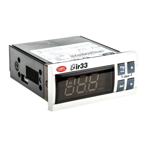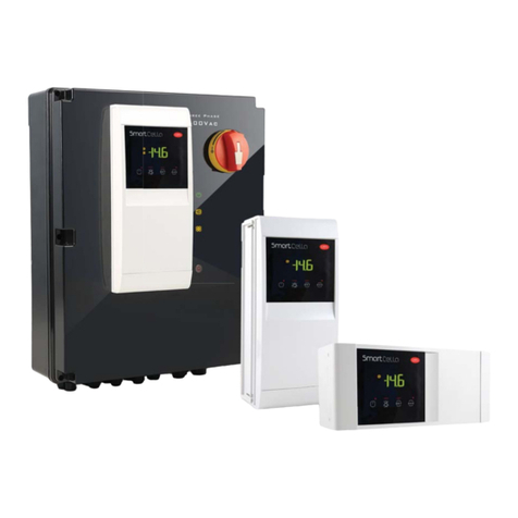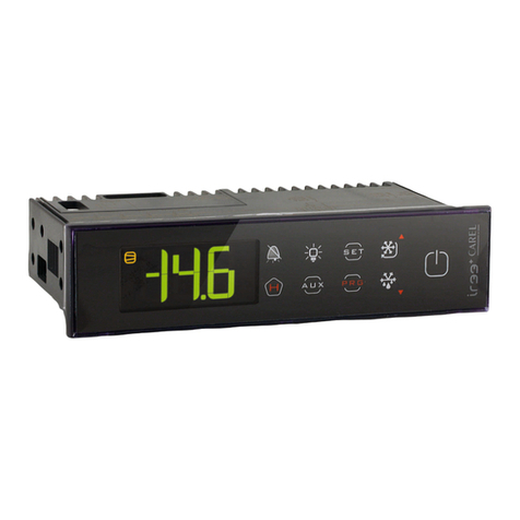
+0500081IE - rel. 1.0 - 18.02.2014
CAREL INDUSTRIES HQs
Via dell’Industria, 11 - 35020 Brugine - Padova (Italy) – Tel. (+39) 0499716611
CAREL si riserva la possibilità di apportare modifiche o cambiamenti ai propri prodotti senza alcun preavviso.
CAREL reserves the right to modify the features of its products without prior notice.
Come accedere e modicare i parametri
tipo “F” (FREQUENTI, non protetti da password), tipo “C” (CONFIGURAZIONE, protetti da password)
Step Azione Effetto Significato
1 Premere PRG per 3 secondi Dopo 3 secondi il display visualizzerà il primo para-
metro, “0”(Password)
L’accesso ai parametri tipo “F” è diretto senza pas-
sword.
2 Premere UP o DOWN Il valore sul display aumenterà o diminuirà Inserire la password“22” per accedere ai parametri
tipo “C”, o qualsiasi altro valore per gli “F”
3 Premere START Il display visualizzerà “St”(Setpoint) E’il valore attuale del Setpoint
4 Premere UP o DOWN Il display scorrerà la lista dei parametri tipo “C”se
avete impostato la password =22 o tipo “F” in caso
contrario
Selezionare il parametro desiderato
5 Premere START Il display visualizzerà il valore del parametro selezionato E’ il valore attuale del parametro
6 Premere UP o DOWN Il valore sul display aumenterà o diminuirà Impostare il valore desiderato
7 Premere START Il display tornerà a visualizzare il nome del parametro Attenzione: l’aggiornamento dei parametri non è
ancora attivo
8 Ripetere gli step 4, 5, 6 e 7 per
tutti i parametri richiesti
9 Premere PRG per 5 secondi Il controllore visualizzerà nuovamente la temperatu-
ra letta dalle sonde
Attenzione: solo ora tutti i parametri saranno
aggiornati Tab. 2
Per entrambi gli accessi (parametri tipo“F”e tipo “C”) è prevista un’uscita automatica per time-out (dopo 1 min in cui non viene premuto
alcun tasto della tastiera), che non aggiorna i parametri.
Accesso ai parametri suddivisi per blocchi funzionali (permette all’utente di scorrere la lista parametri a blocchi)
Una volta ottenuto l’accesso ai parametri di tipo“F”o “C” (vedi tabelle precedenti)
Step Azione Effetto Significato
1 Premere il tasto PRG Il display visualizzerà il nome del blocco funzionale a
cui appartiene il parametro
Esempio ‘CMP’ per i parametri riguardanti il
compressore,‘dEF’per i parametri riguardanti il
sbrinamento
2 Premere il tasto UP o DOWN Il display visualizzerà il nome degli altri blocchi
funzionali
Esempio ‘Fan’ per i parametri riguardanti
i ventilatori
3 Premere il tasto START Il display visualizzerà il nome del primo parametro
del blocco funzionale selezionato
Esempio “F0” per ‘Fan’
Tab. 3
Accesso diretto ai parametri tramite la selezione della categoria
È possibile accedere ai parametri di configurazione, oltre al modo già descritto, anche tramite la categoria (vedi icone e abbreviazioni
nella tabella sottostante) secondo la lista a display in corrispondenza del nome e dell’icona corrispondente. Per accedere direttamente alla
selezione dei parametri raggruppati per categoria premere il tasto PRG, e per modificare il parametro premere DOWN+ START + UP.
Categoria Parametri Scritta Icona
Parametri sonda / ‘Pro’
Parametri regolazione r ‘CtL’
Parametri compressore c ‘CMP’
Parametri sbrinamento d ‘dEF’
Parametri allarmi A ‘ALM’
Parametri ventole F ‘FAn’
Parametri configurazione H configurazione ‘CnF’
Parametri HACCP H HACCP ‘HcP’
Parametri RTC rtc ‘rtc’
Tab. 4
Ripristino allarmi a reset manuale
È possibile resettare tutti gli allarmi a ripristino manuale premendo insieme i tasti PRG e UP per più di 3 s.
Funzione HACCP
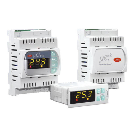
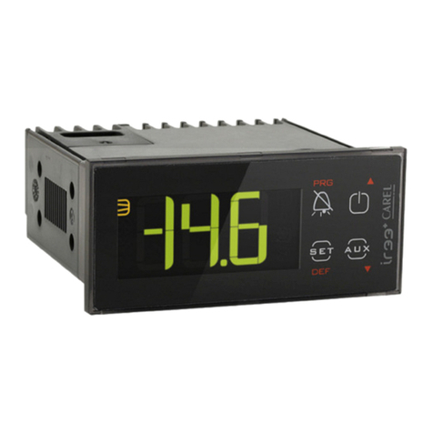
ir33+ wide è conforme alle normative HACCP in quanto permette il monitoraggio della temperatura del cibo conservato.
Allarme “HA”= superamento soglia massima: vengono memorizzati fino a tre eventi HA (HA, HA1, HA2) rispettivamente dal più recente
(HA) al più vecchio (HA2) e una segnalazione HAn che visualizza il numero di eventi HA intervenuti.
Allarme “HF”= mancata tensione per più di 1 minuto e superamento soglia massima AH: vengono memorizzati fino a tre eventi HF (HF,
HF1, HF2) rispettivamente dal più recente (HF) al più vecchio (HF2) e una segnalazione HFn che visualizza il numero di eventi HF intervenuti.
Settaggio allarme HA/HF: parametro AH (soglia di alta temp.); Ad e Htd (Ad + Htd = ritardo allarme HACCP).
Visualizzazione dei dettagli: premere il tasto START per accedere ai parametri HA o HF e scorrere con i tasti UP o DOWN.
Cancellazione allarmi HACCP: premere in qualsiasi momento per 5 s dall’interno del menù il tasto DOWN e START, un messaggio “res”
indicherà l’avvenuta cancellazione dell’allarme attivo. Per cancellare anche gli allarmi memorizzati premere per 5 s la combinazione di questi
tre tasti: DOWN+ START + UP.
Procedura di impostazione dei parametri di default
Per impostare i parametri di default del controllo si procede in questo modo:
• Se “Hdn”= 0:
1. togliere tensione allo strumento;
2. ridare tensione allo strumento tenendo premuto il tasto PRG fino alla comparsa del messaggio “Std” sul display.
Nota: i valori di default vengono impostati solo per i parametri visibili (C e F).
Per maggiori dettagli vedere la tabella Riepilogo parametri di funzionamento.
• Se “Hdn”< > 0:
1. togliere tensione allo strumento;
2. ridare tensione allo strumento tenendo premuto il tasto PRG fino alla comparsa del valore bn0;
3. selezionare il set di parametri di Default, tra 0 e “Hdn”che si vuole impostare per mezzo dei tasti DOWN+ UP;
4. premere il tasto START fino alla comparsa del messaggio “Std”sul display.
Smaltimento del prodotto
The appliance (or the product) must be disposed of separately in accordance with the local waste disposal legislation in force.
Product disposal
The appliance (or the product) must be disposed of separately in accordance with the local waste disposal legislation in force.
ATTENZIONE: separare quanto più possibile i cavi delle sonde e degli ingressi digitali dai cavi dei carichi induttivi e di
potenza per evitare possibili disturbi elettromagnetici. Non inserire mai nelle stesse canaline (comprese quelle dei quadri
elettrici) cavi di potenza e cavi di segnale.
WARNING: separate as much as possible the probe and digital input signal cables from the cables carrying inductive loads
and power cables to avoid possible electromagnetic disturbance. Never run power cables (including the electrical panel
wiring) and signal cables in the same conduits.
NO POWER
& SIGNAL
CABLES
TOGETHER
READ CAREFULLY IN THE TEXT!
NO POWER
& SIGNAL
CABLES
TOGETHER
READ CAREFULLY INTHE TEXT!
AVVERTENZE IMPORTANTI:Il prodotto CAREL è un prodotto avanzato, il cui funzionamento è specificato nella documentazione tec-
nica fornita col prodotto o scaricabile, anche anteriormente all’acquisto, dal sito internet www.carel.com. Il cliente (costruttore, progettista
o installatore dell’equipaggiamento finale) si assume ogni responsabilità e rischio in relazione alla fase di configurazione del prodotto per
il raggiungimento dei risultati previsti in relazione all’installazione e/o equipaggiamento finale specifico. La mancanza di tale fase di studio,
la quale è richiesta/indicata nel manuale d’uso, può generare malfunzionamenti nei prodotti finali di cui CAREL non potrà essere ritenuta
responsabile. Il cliente finale deve usare il prodotto solo nelle modalità descritte nella documentazione relativa al prodotto stesso. La
responsabilità di CAREL in relazione al proprio prodotto è regolata dalle condizioni generali di contratto CAREL editate nel sito www.carel.
com e/o da specifici accordi con i clienti.
IMPORTANT WARNINGS: The CAREL product is a state-of-the-art device, whose operation is specified in the technical documentation
supplied with the product or can be downloaded, even prior to purchase, from the website www.carel.com. The customer (manufacturer,
developer or installer of the final equipment) accepts all liability and risk relating to the configuration of the product in order to reach the
expected results in relation to the specific final installation and/or equipment. The failure to complete such phase, which is required/indi-
cated in the user manual, may cause the final product to malfunction; CAREL accepts no liability in such cases. The customer must use the
product only in the manner described in the documentation relating to the product. The liability of CAREL in relation to its products is spe-
cified in the CAREL general contract conditions, available on the website www.carel.com and/or by specific agreements with customers.
How to access and set parameters
type“F”(FREQUENT, not protected by password), type“C” (CONFIGURATION, password protected)
Step Action Effect Meaning
1 Press PRG for 3 seconds After 3 seconds the display will show the 1st parameter,
“0”(Password)
Access to type“F” parameters is direct without
password
2 Press UP or DOWN The value on the display will increase or decrease.
Enter the password“22”to access the type “C”
parameters or whatever different value for the
type “F” parameters.
3 Press START The display will show“St” (Setpoint) This is the current value of the Setpoint
4 Press UP or DOWN
If the password set is 22 the display will scroll the list of
type“C”parameters (CONFIGURATION) otherwise the list of
type“F”parameters (FREQUENT)
Set the desired value
5 Press START The display will show the parameter name This is the current value of the parameter
6 Press UP or DOWN The value on the display will increase or decrease Set the desired value
7 Press START The display will show the parameter name again IMPORTANT: parameters not yet saved
8Repeat steps 2, 3, 4 & 5 for all
parameters required
9 Press PRG for 5 seconds The controller will display the temperature read by the
probes again
IMPORTANT: only now have all the
parameters been updated Tab. 2
For both types of access (type“F”and type “C”) there is a timeout (no button on the keypad pressed for 1 min), the procedure is ended
without saving the parameter.
Accessing the parameters divided by functional blocks (allows the user to scroll the list of parameters in blocks)
Once having accessed the type “F” or “C” parameters (see tables above)
Step Action Effect Meaning
1 Press PRG The display will show the name of the functional block
that the parameter belongs to
Example ‘CMP’ for the compressor
parameters,‘dEF’ for the defrost parameters
2 Press UP or DOWN The display will show the name of the other functional
blocks Example ‘Fan’ for the fan parameters
3 Press START The display will show the name of the first parameter in
the functional block selected Example “F0” for ‘Fan’
Tab. 3
Directly accessing the parameters by selecting the category
The configuration parameters can also be accessed, in addition to the mode described above, via the category (see the icons and abbreviations in
the table below), according to the list on the display with the corresponding name and icon.To directly access the list of parameters grouped by
category, press the PRG button for at least 1 second and to modify the parameter press DOWN+ START + UP.
Category Parameters Message Icon
Probe parameters / ‘Pro’
Control parameters r ‘CtL
Compressor parameters c ‘CMP’
Defrost parameters d ‘dEF’
Alarm parameters A ‘ALM’
Fan parameters F ‘FAn’
Configuration parameters H configuration ‘CnF’
HACCP parameters H HACCP ‘HcP’
RTC parameters rtc ‘rtc’
Tab. 4
Alarms with manual reset
The alarms with manual reset can be reset by pressing the PRG and UP for more than 3 s.
HACCP function
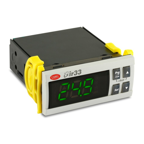
ir33+ is compliant with the HACCP standards in force since it allows the monitoring of the temperature of the stored food.
“HA”alarm = exceeded maximum threshold: up to three HA events are saved (HA, HA1, HA2) respectively from the more recent (HA) to the
oldest (HA2) and a HAn signal that displays the number of occurred HA events.
“HF”alarm = power failure lasting over a minute and exceeded AH maximum threshold: up to three HF events are saved (HF, HF1, HF2)
respectively from the more recent (HF) to the oldest (HF2) and a HFn signal that displays the number of occurred HF events.
HA/HF alarm setting: AH parameter (high temp. threshold); Ad and Htd (Ad+Htd = HACCP alarm activation delay).
Display of the details: access to HA or HF parameters pressing the START button and use UP or DOWN buttons to glance over.
HACCP alarm erasing: press the DOWN and SET buttons for more than 5 seconds, the message ‘res’indicates that the alarm have been
deleted. To cancel the saved alarms press the DOWN+ START + UP buttons for more than 5 seconds.
Procedure for setting the default parameter values
To set the default parameter values on the controller, proceed as follows:
• If “Hdn”= 0:
1: switch the instrument off;
2: switch the instrument back on, holding the PRG button until the message“Std” is shown on the display.
Note: the default values are only set for the visible parameters (C and F). For further details see table“Summary of operating parameters”.
• If “Hdn”< > 0:
1: switch the instrument off;
2: switch the instrument back on, holding the PRG button until the value bn0 is shown on the display;
3: select the set of default parameters, between 0 and“Hdn”, using the DOWN and UP buttons;
4: press the START button until the message “Std” is shown on the display.
